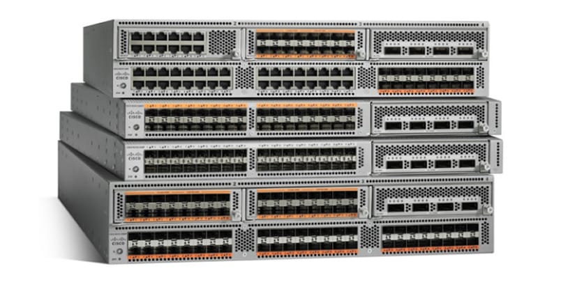
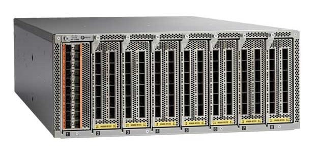
Cisco Nexus 5000 Series Switches
| Product Type | Data Center Switches |
|---|---|
| Status |
End of Sale
EOL Details
|
| Series Release Date | 08-APR-2008 |
| End-of-Sale Date | 05-MAY-2021 |
| End-of-Support Date | 31-MAY-2026 |
| Diagram | Visio Stencil (10 MB .zip file) |
|
This product is supported by Cisco, but is no longer being sold.
|
|
- US/Canada 800-553-2447
- Worldwide Support Phone Numbers
- All Tools
 Feedback
 Feedback
-
Top Search Results
Key Information
Customers Also Viewed
Saved Content
-
You can now save documents for easier access and future use. Saved documents for this product will be listed here, or visit the My Saved Content page to view and manage all saved content from across Cisco.com.
Log in to see your Saved Content.
Recent Security Notices
- 25-Feb-2026
- 25-Feb-2026
- 27-Aug-2025
- 27-Aug-2025
- 27-Aug-2025
Document Categories
-
Data Sheets and Product Information
- Cisco Nexus 5600 Platform 10-Gbps Switches Data Sheet
- Cisco Nexus 5600 Platform 40-Gbps Switches Data Sheet
- Cisco Nexus 2000 and Nexus 5500 Switches Data Sheet
Data Sheets
- End-of-Sale and End-of-Life Announcement for the Cisco Nexus 5500, 5600 and 6000 NX-OS 7.3 all versions
- End-of-Sale and End-of-Life Announcement for the Cisco Nexus 56128P, 5624Q, 5648Q Switches
- End-of-Sale and End-of-Life Announcement for the Cisco Nexus 5600 100G Daughter Card
- End-of-Sale and End-of-Life Announcement for the CiscoONE (C1) Legacy PIDs - C1-N9000, C1-N7000, C1-N5000, C1-N3000, C1-MDS 9000
- End-of-Sale and End-of-Life Announcement for the Cisco B22 HP FEX Bundles
- Annonce d’arrêt de commercialisation et de fin de vie de Cisco Nexus 2232PP, 2232TM-E, 2332TQ, 2348TQ Fabric Extenders
- End-of-Sale and End-of-Life Announcement for the Cisco B22 DELL FEX Bundles
- End-of-Sale and End-of-Life Announcement for the Cisco Nexus 5500 Series Switches
- End-of-Sale and End-of-Life Announcement for the Cisco Nexus 5500, 5600 and 6000 NX-OS 7.1
- End-of-Sale and End-of-Life Announcement for the Cisco B22 FEX Bundles for IBM & Fujitsu
- End-of-Sale and End-of-Life Announcement for the Cisco NX-OS Software Releases 5.0 and 5.1 for the Cisco Nexus 2000 Series Fabric Extenders and 5000 Series Switches
- End-of-Sale and End-of-Life Announcement for the Cisco Nexus 5600-2000 Bundles
- End-of-Sale and End-of-Life Announcement for the Cisco Nexus Fixed Bundles
- End-of-Sale and End-of-Life Announcement for the Cisco NX-OS Software Release 7.0 for Cisco Nexus 2000 Series Fabric Extenders, Nexus 5000 Series Switches, and Nexus 6000 Series Switches
- End-of-Sale and End-of-Life Announcement for the Cisco NX-OS Software Release 7.2 for Cisco Nexus 2000 Series Fabric Extenders, Nexus 5000 Series Switches, and Nexus 6000 Series Switches
End-of-Life and End-of-Sale Notices
-
Security Notices
-
Applicable to Multiple Models
- Field Notice: FN63893 - N55-PAC-1100W PSU Silent Reload Failure - Replace on Failure
- Field Notice: FN - 72115 - Nexus Product Line: QuoVadis Root CA 2 Decommission Might Affect Smart Licensing and Smart Call Home Functionality - Software Upgrade Recommended
- Field Notice: FN - 72015 - Specific Releases of Data Center Network Manager Release 7.X Affected by Adobe Flash End-of-Life - Software Upgrade Recommended
- Field Notice: FN - 64094 - Nexus 5596/UCS FI 6296 - System Fails to Boot After a Power Cycle - Workaround Provided
- Field Notice: FN - 64180 - Nexus 55xx, 56xx, and 600x Series Switch Platforms SNMPd process restart when process reaches Memory Threshold - Software Upgrade Recommended
- Field Notice: FN - 64110 - Nexus 5600 or Nexus 6001 Series Switch Might Hang or Reset - BIOS/Firmware Upgrade Recommended
- Field Notice: FN - 64125 - In Some Nexus 5672, 56128, and 5696 Switches, Nondisruptive ISSUs Might Fail and Require Manual Intervention for System Recovery
-
Cisco Nexus 56128P Switch
- Field Notice: FN - 63560 - Nexus 5000 System Restart after 130 days of uptime - Software Update or Planned Restart Required
- Field Notice: FN - 63302 - New Cisco OUI for MDS 9000, Nexus 5000 and UCS 6100 may impact recognition of new equipment by Cisco FMS - Software Upgrade Recommended
Field Notices
- Cisco NX-OS Software Link Layer Discovery Protocol Denial of Service Vulnerability
- Cisco Nexus 3600 and 9500-R Series Switching Platforms Layer 2 Loop Denial of Service Vulnerability
- Cisco Nexus 3000 and 9000 Series Switches Intermediate System-to-Intermediate System Denial of Service Vulnerability
- Cisco Nexus 3000 and 9000 Series Switches Protocol Independent Multicast Version 6 Denial of Service Vulnerability
- Cisco NX-OS Software Command Injection Vulnerability
- Cisco NX-OS Software Sensitive Log Information Disclosure Vulnerability
- Multiple Cisco Products Switch Integrated Security Features DHCPv6 Denial of Service Vulnerability
- Cisco NX-OS Software Image Verification Bypass Vulnerability
- Cisco Nexus 3000 and 9000 Series Switches Health Monitoring Diagnostics Denial of Service Vulnerability
- Cisco Nexus 3000 and 9000 Series Switches Command Injection Vulnerability
- Cisco NX-OS Software CLI Command Injection Vulnerability
- Cisco NX-OS Software DHCPv6 Relay Agent Denial of Service Vulnerability
- Cisco NX-OS Software Python Sandbox Escape Vulnerabilities
- Cisco NX-OS Software Command Injection Vulnerability
- Cisco NX-OS Software Bash Arbitrary Code Execution and Privilege Escalation Vulnerabilities
Security Advisories, Responses and Notices
-
-
Release and Compatibility
- Cisco Nexus 5600 Series Release Notes, Cisco NX-OS Release 7.x
- Cisco Nexus 5500 Series Release Notes, Cisco NX-OS Release 7.x
- Minimum Recommended Cisco NX-OS Releases for Cisco Nexus 5600 Series Switches
- Minimum Recommended Cisco NX-OS Releases for Cisco Nexus 5500 Series Switches
- Minimum Recommended Cisco NX-OS Releases for Cisco Nexus 5000 Series Switches
- Cisco FindIT Network Manager - Device Support List
- Cisco Programmable Fabric with VXLAN BGP EVPN Release Notes
- Cisco Nexus 5000 Series and Cisco Nexus 2000 Series Release Notes for Cisco NX-OS Release 5.0(3)N1(1b) and NX-OS Release 5.0(3)N1(1c)
- Cisco Nexus 5000 Series and Cisco Nexus 2000 Series Release Notes, Cisco NX-OS Release 5.1(3)N2(1c), Cisco NX-OS Release 5.1(3)N2(1b), Release 5.1(3)N2(1a), and Release 5.1(3)N2(1)
- Cisco Nexus 5000 Series and Cisco Nexus 2000 Series Release Notes, Cisco NX-OS Release 5.1(3)N1(1a) and Release 5.1(3)N1(1)
- Cisco Nexus 5000 Series and Cisco Nexus 2000 Series Release Notes for Cisco NX-OS Release 5.0(3)N2(2b), Release 5.0(3)N2(2a), Release 5.0(3)N2(2), and Release 5.0(3)N2(1)
- Cisco Nexus 5000 Series and Cisco Nexus 2000 Series Release Notes for Cisco NX-OS Release 5.0(2)N1(1), NX-OS Release 5.0(2)N2(1), and NX-OS Release 5.0(2)N2(1a)
- FAQs
- Cisco Nexus 5000 Series and Cisco Nexus 2000 Series Release Notes, Releases 4.2(1)N1(1), 4.2(1)N2(1), and 4.2(1)N2(1a)
- Cisco Nexus 5000 Series and Cisco Nexus 2000 Series Release Notes, Releases 4.1(3)N1(1), 4.1(3)N1(1a), 4.1(3)N2(1), and 4.1(3)N2(1a)
Release Notes
-
Reference
- Command Reference BookMap1
- Cisco Nexus 5000 Series Interfaces Command Reference
- Cisco Nexus 5600 Series Switches Layer2 Command Reference
- Cisco Nexus 5500 Series Layer 2 Interfaces Command Reference
- Cisco Nexus 5600 Series NX-OS Interfaces Command Reference
- Cisco Nexus 5500 Series NX-OS Interfaces Command Reference
- Cisco Nexus 5000 Series Layer 2 Switching Command Reference
- Cisco Nexus 5600 Series Switches Interfaces Command Reference
- Cisco Nexus 5500 Series Interfaces Command Reference
- Cisco Nexus 5000 Series NX-OS Unicast Routing Command Reference
- Cisco Nexus 5600 Series NX-OS Unicast Routing Command Reference
- Cisco Nexus 5000 Series NX-OS Virtual Port Channel Command Reference
- Cisco Nexus 5500 Series NX-OS Interfaces Command Reference
- Cisco Nexus 5600 Series NX-OS System Management Command Reference
- Cisco Nexus 5500 Series NX-OS System Management Command Reference
Command References
- License and Copyright Information for Cisco NX-OS Software, Release 5.2(1)N1(8b) (PDF - 1 MB)
- License and Copyright Information for Cisco NX-OS Software, Release 5.2(1)N1(8a) (PDF - 1 MB)
- License and Copyright Information for Cisco NX-OS Software, Release 5.2(1)N1(8) (PDF - 1 MB)
- License and Copyright Information for Cisco NX-OS Software, Release 5.1(3)N2(1) (PDF - 1 MB)
- License and Copyright Information for Cisco NX-OS Software, Release 5.2(1)N1(6) (PDF - 861 KB)
- License and Copyright Information for Cisco NX-OS Software, Release 5.2(1)N1(7) (PDF - 859 KB)
- License and Copyright Information for Cisco NX-OS Software, Release 5.2(1)N1(5) (PDF - 872 KB)
- License and Copyright Information for Cisco NX-OS Software, Release 5.2(1)N1(4) (PDF - 132 KB)
- License and Copyright Information for Cisco NX-OS Software, Release 5.2(1)N1(3) (PDF - 133 KB)
- License and Copyright Information for Cisco NX-OS Software, Release 5.2(1)N1(2) (PDF - 132 KB)
- License and Copyright Information for Cisco NX-OS Software, Release 5.2(1)N1(2a) (PDF - 132 KB)
- License and Copyright Information for Cisco NX-OS Software, Release 5.2(1)N1(1b) (PDF - 132 KB)
- License and Copyright Information for Cisco NX-OS Software, Release 5.2(1)N1(1a) (PDF - 132 KB)
- License and Copyright Information for Cisco Nexus NX-OS Release 6.0(2)N1(1) (PDF - 133 KB)
- License and Copyright Information for Cisco Nexus NX-OS Software, Release 5.0(2)N1(3) (PDF - 219 KB)
Licensing Information
-
Design
- Deploying ITD: Server Traffic distribution Using Direct Server Return (PDF - 2 MB)
Design Guides
-
Install and Upgrade
- Cisco Nexus 5600 Series NX-OS Software Upgrade and Downgrade Guide, Release 7.3(17)N1(1)
- Cisco Nexus 5500 Series NX-OS Software Upgrade and Downgrade Guide, Release 7.3(17)N1(1)
- Cisco Nexus 5600 Series NX-OS Software Upgrade and Downgrade Guide, Release 7.3(16)N1(1)
- Cisco Nexus 5500 Series NX-OS Software Upgrade and Downgrade Guide, Release 7.3(16)N1(1)
- Cisco Nexus 5600 Series NX-OS Software Upgrade and Downgrade Guide, Release 7.3(15)N1(1)
- Cisco Nexus 5600 Series NX-OS Software Upgrade and Downgrade Guide, Release 7.3(14)N1(1)
- Cisco Nexus 5600 Series NX-OS Software Upgrade and Downgrade Guide, Release 7.3(13)N1(1)
- Cisco Nexus 5600 Series NX-OS Software Upgrade and Downgrade Guide, Release 7.3(12)N1(1)
- Cisco Nexus 5500 Series NX-OS Software Upgrade and Downgrade Guide, Release 7.3(13)N1(1)
- Cisco Nexus 5500 Series NX-OS Software Upgrade and Downgrade Guide, Release 7.3(12)N1(1)
- Cisco Nexus 5500 Series NX-OS Software Upgrade and Downgrade Guide, Release 7.3(12)N1(1)
- Cisco Nexus 5500 Series NX-OS Software Upgrade and Downgrade Guide, Release 7.3(11)N1(1)
- Cisco Nexus 5600 Series NX-OS Software Upgrade and Downgrade Guide, Release 7.3(11)N1(1)
- Cisco Nexus 5600 Series NX-OS Software Upgrade and Downgrade Guide, Release 7.3(10)N1(1)
- Cisco Nexus 5600 Series NX-OS Software Upgrade and Downgrade Guide, Release 7.3(9)N1(1)
Install and Upgrade Guides
- Upgrade Nexus 5500 and 5600 NX-OS Software
Install and Upgrade TechNotes
-
Configuration
-
Cisco Nexus 5672UP Switch
-
Cisco Nexus 5596T Switch
- Configure Nexus 5500 Compliance with FC-PI-4 at 8G FC Speed
- Configure and Verify Maximum Transmission Unit on Nexus Platforms
- Create Topologies for Routing over Virtual Port Channel
- Configure Jumbo MTU on Nexus 5000 and 7000 Series
- Configure FlexPod and FCoE with VPC and NetApp Storage
- Configure QoS on a UCS and Nexus 5000
- Upgrade Cisco NX-OS For Cisco Nexus 5000 Series Switch
- Nexus N5500, 5600 and N6000 Role Base Access Control (RBAC)
- Nexus 5500 to Nexus 7000 Multi-Hop FCoE Configuration Example
- Nexus 5500 Adapter-FEX Configuration Example
- Nexus 5000 NPIV FCoE with FCoE NPV Attached UCS Configuration Example
- Nexus 5000 Series Switch ERSPAN Configuration Example
Configuration Examples and TechNotes
- Cisco Nexus 5600 Series NX-OS Fibre Channel over Ethernet Configuration Guide, Release 7.x
- Cisco Nexus 5600 Series NX-OS System Management Configuration Guide, Release 7.x
- Cisco Nexus 5500 Series NX-OS System Management Configuration Guide, Release 7.x
- Cisco Nexus 5600 Series NX-OS Layer 2 Switching Configuration Guide, Release 7.x
- Cisco Nexus 5600 Series NX-OS Unicast Routing Configuration Guide, Release 7.x
- Cisco Nexus 5500 Series NX-OS Security Configuration Guide, Release 7.x
- Cisco Nexus 5600 Series NX-OS Interfaces Configuration Guide, Release 7.x
- Cisco Nexus 5500 Series NX-OS Interfaces Configuration Guide, Release 7.x
- Cisco Nexus 5600 Series NX-OS Security Configuration Guide, Release 7.x
- Cisco Nexus 5500 Series NX-OS Layer 2 Switching Configuration Guide, Release 7.x
- Cisco Nexus 5500 Series NX-OS Unicast Routing Configuration Guide, Release 7.x
- Verified Scalability for Cisco Nexus 5500 Series NX-OS Release 7.3(0)N1(1)
- Cisco Nexus 5500 Series NX-OS Unicast Routing Configuration Guide, Release 6.x
- Cisco Nexus 5500 Series NX-OS Security Configuration Guide, Release 6.x
- Cisco Nexus 5000 Series NX-OS Security Configuration Guide, Release 5.0(2)N1(1)
Configuration Guides
- Cisco Nexus 5000 and 6000 Series NX-OS Programmability Guide
Programming Guides
-
-
Maintain and Operate
-
Cisco Nexus 5500 NX-OS Software Release 6.0(2)N1(1)
-
Cisco Nexus 5000 NX-OS Software Release 5.2(1)N1(1)
-
Cisco Nexus 5000 NX-OS Software Release 5.1(3)N1(1)
- Cisco Nexus 5000 Series NX-OS Adapter FEX Operations Guide, Release 5.1(3)N1(1)
- Cisco Nexus 5000 Series NX-OS FabricPath Operations Guide, Release 5.1(3)N1(1)
- Cisco Nexus 5000 Series NX-OS FCoE Operations Guide, Release 5.1(3)N1(1)
- Cisco Nexus 5000 Series NX-OS Interfaces Operations Guide, Release 5.1(3)N1(1)
-
Cisco Nexus 5000 NX-OS Software Release 5.0(3)N2(1)
Maintain and Operate Guides
-
-
Troubleshooting
- Cisco Nexus 5500 Series NX-OS System Messages Reference
- Cisco Nexus 5600 Series NX-OS System Messages Reference
- Nexus 5000 Series NX-OS System Message Reference
Error and System Messages
- Cisco Nexus 5000 Troubleshooting Guide
- Cisco Nexus 5500 Troubleshooting Guide
Troubleshooting Guides
- Understand Virtual Port Channel (vPC) Enhancements
- Troubleshoot Nexus Cheat Sheet for Beginners
- Understand Nexus 5500 and 5600 Series Switch Replacement Procedure
- Nexus 5000 and Single Homed FEX vPC Design Best Practices
- QLogic QLE8262 CNA - Host Does Not Log into Fabric
- Delay Before Password Prompt Appears while you Login via SSH/Telnet
- Nexus 5500 Scheduler Functionality with EEM Scripts
- Troubleshoot Nexus 5000 Port-channel Loadbalancing
- Nexus 5010/5020 Switches "%NOHMS-2-NOHMS_DIAG_Error" Message Interpretation
- FlexPod Nexus 5k in vPC behavior during disruption
- Troubleshoot a CFS Lock on Nexus 5000 Series Switches
- FlexPod Common Performance Problems
- L2MP based forwarding across vPC peer-link in Carmel ASIC based switches(Nexus 5548/5596)
- UCS C-Series Rack Servers VIC Connectivity Options
- Nexus 7000 Series Switch Problem with Remote User Authentication via SSH with a TACACS account
Troubleshooting TechNotes
-
Literature
- Gain Network Programmability and Automation with Open Cisco NX-OS (PDF - 598 KB)
Solution Overviews
- Monitor Microbursts on Cisco Nexus 5600 Platform and Cisco Nexus 6000 Series Switches
- Implementing Buffer Utilization Histogram on Cisco Nexus 5600 and Nexus 6000 Switch Families
- QLogic Adapters and Cisco Nexus 5000 Series Switches: FCoE Design Guide (PDF - 2 MB)
- The Next Phase of Datacenter Development (PDF - 204 KB)
- Cisco Nexus 5548P Switch Architecture
- University of Arizona Increases Flexibility While Reducing Total Cost of Ownership with Cisco Nexus (PDF - 1 MB)
White Papers
-
Log in to see available downloads.
-
-
Below are the models within the Cisco Nexus 5000 Series Switches product line.
Unless specified, documentation for the Cisco Nexus 5000 Series Switches is applicable to all models.
Cisco Nexus 5500 Switch Models
- Cisco Nexus 5548UP Switch - End-of-Support Date: 31-May-2024
- Cisco Nexus 5596T Switch - End-of-Support Date: 31-May-2024
- Cisco Nexus 5596UP Switch - End-of-Support Date: 31-May-2024
Cisco Nexus 5600 Switch Models
- Cisco Nexus 5624Q Switch - End-of-Support Date: 30-Sep-2025
- Cisco Nexus 5648Q Switch - End-of-Support Date: 30-Sep-2025
- Cisco Nexus 5672UP Switch - End-of-Support Date: 31-Aug-2026
- Cisco Nexus 5672UP-16G Switch - End-of-Support Date: 31-May-2026
- Cisco Nexus 5696Q Switch - End-of-Support Date: 31-May-2026
- Cisco Nexus 56128P Switch - End-of-Support Date: 30-Sep-2025
