FlexPod Datacenter Zero Trust Framework Design Guide
Available Languages
Bias-Free Language
The documentation set for this product strives to use bias-free language. For the purposes of this documentation set, bias-free is defined as language that does not imply discrimination based on age, disability, gender, racial identity, ethnic identity, sexual orientation, socioeconomic status, and intersectionality. Exceptions may be present in the documentation due to language that is hardcoded in the user interfaces of the product software, language used based on RFP documentation, or language that is used by a referenced third-party product. Learn more about how Cisco is using Inclusive Language.
- US/Canada 800-553-2447
- Worldwide Support Phone Numbers
- All Tools
 Feedback
 Feedback
In partnership with:

About the Cisco Validated Design Program
The Cisco Validated Design (CVD) program consists of systems and solutions designed, tested, and documented to facilitate faster, more reliable, and more predictable customer deployments. For more information, go to: http://www.cisco.com/go/designzone.
The FlexPod Datacenter solution is a validated approach for deploying Cisco and NetApp technologies and products to build shared private and public cloud infrastructure. Cisco and NetApp have partnered to deliver a series of FlexPod solutions that enable strategic data-center platforms. The success of the FlexPod solution is driven by its ability to evolve and incorporate both technology and product innovations in the areas of management, computing, storage, networking, and security. This document explains the design details of incorporating and implementing various tools, technologies, and products to deliver a Zero Trust security framework for FlexPod Datacenter.
FlexPod delivers an integrated architecture that incorporates compute, storage, and network design best practices, thereby minimizing IT risks by validating the integrated architecture to ensure compatibility between various components. The solution also addresses IT pain points by providing documented design guidance, deployment guidance, and support that can be used in various stages (planning, designing, and implementation) of a deployment.
FlexPod Datacenter delivers the following key benefits:
● Simpler and programmable infrastructure: FlexPod infrastructure delivered as infrastructure-as-code through a single partner integrable open API.
● Latest hardware and software compute innovations: policy-based configurations, delivered using Cisco Intersight, to deploy and manage the latest processor, memory, network, and power/cooling improvements.
● Storage Modernization: deliver high-speed, consistent, low latency, multi-tenant storage using a range of NetApp storage arrays.
● Innovative cloud operations: continuous feature delivery and no need for maintaining on-premises physical or virtual machines supporting management functions.
● Built for investment protections: design ready for future compute technologies such as liquid cooling and high-Wattage CPUs; CXL-ready.
A Zero Trust Security Framework is a comprehensive approach to network security that assumes no user, system, or device can be trusted by default, regardless of its location relative to the network perimeter. It operates under the principle of "never trust, always verify," meaning that every access request is thoroughly verified before granting access, irrespective of where it originates from. The Zero Trust Framework strives to protect modern digital environments by leveraging network segmentation, preventing lateral movement, providing Layer 7 threat prevention, and simplifying granular user-access control.
Implementing Zero Trust framework on a FlexPod infrastructure provides following additional benefits:
● Enhanced Security: By treating every access request as a potential threat, Zero Trust significantly reduces the risk of data breaches and other security incidents.
● Greater Visibility: Constant monitoring of network activities provides a comprehensive view of the network, enabling quick identification and response to any unusual or suspicious activities.
● Reduced Attack Surface: By enforcing least privilege access and micro-segmentation, Zero Trust minimizes the potential points of vulnerability in the network.
● Improved Compliance: The stringent security controls in Zero Trust can help organizations meet compliance requirements for data protection and privacy.
● Efficient Incident Response: Quickly detect, block, and respond to threats. Verify data integrity and implement data loss prevention.
● Protection Against Internal Threats: Zero Trust considers the possibility of threats coming from inside the network, offering protection against insider threats as well as external ones.
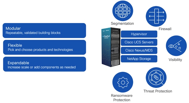
The Zero Trust Framework for the FlexPod solution incorporates various additional security components by Cisco and NetApp including Cisco Secure Firewall Threat Defense (FTD), Cisco Secure Network Analytics (previously Stealthwatch), Cisco Secure Workload (previously Tetration), and NetApp Ransomware Protection.
If you’re interested in understanding the FlexPod design and deployment details, including the configuration of various elements of design and associated best practices, see the Cisco Validated Designs for FlexPod: https://www.cisco.com/c/en/us/solutions/design-zone/data-center-design-guides/flexpod-design-guides.html.
This chapter contains the following:
● Audience
The FlexPod Datacenter solution incorporates various security technologies by Cisco and NetApp to follow the security design best practices for delivering a hardened platform. Zero Trust framework introduces several secure design principles which require additional security and visibility products. The Zero Trust framework design requirements can be summarized as:
● Never assume trust, always verify, and enforce least privilege access.
● Establish and enforce trust on platforms. Implement device and protocol hardening.
● Reduce the attack surface using segmentation and control traffic flow between segments.
● Complete visibility of processes, devices, and workloads.
● Quickly detect, block, and respond to threats. Verify data integrity and implement data loss prevention.
● Provide an automated, flexible, standardized, and layered approach to security.
To deliver a Zero Trust framework on FlexPod, several technologies and security products are introduced in following key areas:
● Platform Resilience: device and protocol hardening including traffic isolation, role-based access control (RBAC), and utilizing secure connectivity.
● Segmentation and Control: multi-tenancy design using virtual routing and forwarding (VRF), VLANs, and Cisco Firewall Threat Defense.
● Visibility and Monitoring: network and OS level visibility and anomaly detection using Cisco Secure Network Analytics and Cisco Secure Workload.
● Threat Protection and Response: controlling the breach and recover quickly using Cisco Secure Workload and NetApp Ransomware Protection.
● Device Automation: automated infrastructure deployment including day-2 tenant setup using Ansible.
The intended audience of this document includes but is not limited to IT architects, sales engineers, field consultants, professional services, IT managers, partner engineering, and customers who want to take advantage of an infrastructure built to deliver IT efficiency and enable IT innovation.
This document provides design guidance around incorporating the Zero Trust framework design principles in a FlexPod Datacenter environment. The document introduces various design elements and describes various considerations and best practices for a successful deployment of additional security technologies and products such as Cisco Secure Firewall Threat Defense, Cisco Secure Network Analytics, Cisco Secure Workload, and NetApp Ransomware Protection.
These design elements distinguish this FlexPod Datacenter CVD from previous designs:
● Enhanced platform security by implementing additional device and protocol hardening.
● Multi-tenant design where data traffic between various tenants is controlled using Cisco Secure Firewall Threat Defense.
● Cisco Secure Workload (formerly Tetration) and Cisco Secure Network Analytics (formerly Stealthwatch) for network and process level visibility.
● Threat protection using Cisco Secure Workload.
● Data loss prevention using NetApp Ransomware Protection.
The Zero Trust framework for FlexPod solution offers the following key benefits for securing your infrastructure:
● Cisco security technologies: FlexPod leverages Cisco's advanced security technologies like segmentation, firewalls, intrusion detection/prevention systems, Cisco Secure workload, and Cisco secure network analytics to identify, mitigate, and protect against various cyber threats.
● NetApp security features: NetApp storage solutions offer encryption at rest and in transit, data lifecycle management, and role-based access control to secure sensitive data. NetApp Autonomous Ransomware Protection utilizes machine learning to provide a comprehensive data protection solution at negligible performance impact.
● FlexPod security features: FlexPod designs follow various security best practices such as secure boot and firmware updates, disabling insecure users and protocols, and employing role-based access control to prevent unauthorized modifications and vulnerabilities.
FlexPod designs are modular and scalable in nature therefore the security framework integrated design maintains the modularity and scalability while providing an automated, flexible, standardized, and layered approach to security.
This chapter contains the following:
● Cisco Unified Computing System X-Series
● Cisco Nexus 93600CD-GX Ethernet Switch
● Infrastructure as Code with Ansible
● Cisco Secure Firewall Threat Defense Virtual
● Cisco Secure Firewall Management Center
● Cisco Secure Network Analytics
● Intel Confidential Computing
● NetApp Security and Ransomware Protection
FlexPod Datacenter architecture is built using the following infrastructure components for compute, network, and storage:
● Cisco Unified Computing System (Cisco UCS)
● Cisco Nexus and Cisco MDS switches
● NetApp All Flash FAS (AFF), FAS, and All SAN Array (ASA) storage systems
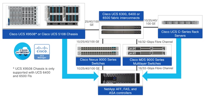
All the FlexPod components have been integrated so that you can deploy the solution quickly and economically while eliminating many of the risks associated with researching, designing, building, and deploying similar solutions from the foundation. One of the main benefits of FlexPod is its ability to maintain consistency at scale. Each of the component families shown in Figure 2. (Cisco UCS, Cisco Nexus, Cisco MDS, and NetApp controllers) offers platform and resource options to scale up or scale out the infrastructure while supporting the same features.
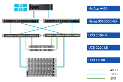
The Zero Trust framework for FlexPod Datacenter solution is built using the following hardware components:
● Cisco UCS X9508 Chassis with Cisco UCSX-I-9108-100G Intelligent Fabric Modules and up to eight Cisco UCS X210c M7 Compute Nodes.
● Fifth-generation Cisco UCS 6536 Fabric Interconnects to support 10/25/40/100GbE and 16/32GbFC connectivity from various components.
● Cisco UCS C220 M7 or C240 M7 Rack Mount Servers attached directly to the Fabric Interconnects.
● High-speed Cisco NX-OS-based Cisco Nexus C93600CD-GX switching to support up to 400GE ethernet connectivity.
● NetApp AFF A400 end-to-end NVMe storage with up to 100GE connectivity and 32G FC connectivity
The management software components of the Zero Trust framework for FlexPod consist of:
● Cisco Intersight platform to deploy the Cisco UCS components and maintain and support the FlexPod components.
● Cisco Intersight Assist Virtual Appliance to help connect NetApp AIQUM, Cisco Nexus (and MDS) Switches, and VMware vCenter to Cisco Intersight.
● NetApp Active IQ Unified Manager to monitor and manage the storage and for NetApp ONTAP integration with Cisco Intersight.
● VMware vCenter to set up and manage the virtual infrastructure as well as Cisco Intersight integration.
FlexPod Security Hardening
FlexPod has always been constructed with security at its core, ensuring a safe and secure platform for users. The design not only emphasizes system functionality but also data protection and traffic isolation. The security fundamentals of FlexPod are well-documented in the technical report, TR-4984-1123, providing comprehensive insights into its safe and secure operations. NetApp TR-4984-1123, is a comprehensive approach to safeguarding FlexPod infrastructure by implementing security controls and best practices across all layers: compute, network, storage, and virtualization. This multi-layered defense aims to minimize the attack surface and mitigate the risk of data breaches, unauthorized access, and other security incidents. FlexPod Hardening Technical Report (TR) highlights:
● Integrated Security: integrated approach to security hardening covers all layers of the solution stack and ensures that all aspects of the infrastructure are secure.
● Best Practices Guidance: provide detailed guidance based on hardening guides from VMWare, NetApp, and Cisco across the FlexPod infrastructure.
● Secure by Design: solution designed with security in mind from the ground up where security isn't just an afterthought or add-on, but a fundamental part of the solution's design and implementation.
Note: FlexPod hardening is an ongoing process that should be reviewed and updated regularly to reflect changes in security threats and best practices.
This Cisco Validated Design (CVD) enhances the existing FlexPod security fundamentals by incorporating additional software components for improved visibility, segmentation, threat mitigation, and ransomware protection.
Cisco Unified Computing System X-Series
Cisco UCS X-Series simplifies the data-center design by providing flexible server options. A single server type, supporting a broader range of workloads results in fewer different data center products to manage and maintain. Cisco Intersight manages Cisco UCS X-Series as well as integrates with Cisco and third-party devices, including Cisco Nexus and MDS switches, VMware vCenter and NetApp storage, to provide visibility, optimization, and orchestration from a single platform.
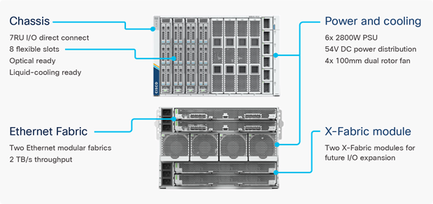
Cisco UCS X9508 Chassis
The Cisco UCS X-Series chassis is engineered to be adaptable and flexible. Figure 4 shows the Cisco UCS X9508 chassis only has a power-distribution midplane. This midplane-free design provides fewer obstructions for better airflow. For I/O connectivity, vertically oriented compute nodes intersect with horizontally oriented fabric modules, allowing the chassis to support future fabric innovations. Cisco UCS X9508 Chassis’ superior packaging enables larger compute nodes, thereby providing more space for actual compute components, such as memory, GPU, drives, and accelerators. Improved airflow through the chassis enables support for higher power components, and more space allows for future thermal solutions such as liquid cooling.
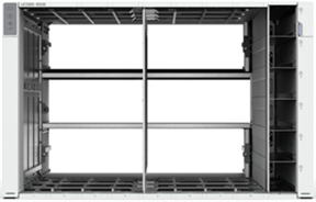
The Cisco UCS X9508 7-Rack-Unit (7RU) chassis has eight flexible slots. These slots can house a combination of compute nodes and a pool of current and future I/O resources that includes GPU accelerators, disk storage, and nonvolatile memory. At the top rear of the chassis are two Intelligent Fabric Modules (IFMs) that connect the chassis to upstream Cisco UCS 6400 or 6500 Series Fabric Interconnects. At the bottom rear of the chassis are slots to house X-Fabric modules that can flexibly connect the compute nodes with I/O devices. Six 2800W Power Supply Units (PSUs) provide 54V power to the chassis in multiple redundancy configurations. A higher voltage allows efficient power delivery with reduced power loss. Efficient, 100mm, dual counter-rotating fans deliver industry-leading airflow and power efficiency and optimized thermal algorithms enable different cooling modes to best support your environment.
Cisco UCSX-I-9108-100G Intelligent Fabric Modules
Cisco UCS X9508 Chassis 100-Gbps network connectivity is provided by a pair of Cisco UCSX-I-9108-100G Intelligent Fabric Modules (IFMs). Like the fabric extenders used in the Cisco UCS 5108 Blade Server Chassis, these modules carry all network traffic to a pair of Cisco UCS 6536 Fabric Interconnects (FIs). IFMs also host the Chassis Management Controller (CMC) for chassis management. In contrast to systems with fixed networking components, Cisco UCS X9508’s midplane-free design enables easy upgrades to new networking technologies as they emerge making it straightforward to accommodate new network speeds or technologies in the future.

Each IFM supports eight 100Gb uplink ports for connecting the Cisco UCS X9508 Chassis to the FIs and 8 100Gb or 32 25Gb server ports for the eight compute nodes. IFM server ports can provide up to 200 Gbps of unified fabric connectivity per compute node across the two IFMs. The uplink ports connect the chassis to the Cisco UCS FIs, providing up to 1600Gbps connectivity across the two IFMs. The unified fabric carries management, VM, and Fibre Channel over Ethernet (FCoE) traffic to the FIs, where server management traffic is routed to the Cisco Intersight cloud operations platform, FCoE traffic is forwarded to either native Fibre Channel interfaces through unified ports on the FI (to Cisco MDS switches) and data Ethernet traffic is forwarded upstream to the data center network using Cisco Nexus switches.
Cisco UCS X210c M7 Compute Node
The Cisco UCS X9508 Chassis is designed to host up to 8 Cisco UCS X210c M7 Compute Nodes. Figure 6 shows the hardware details of the Cisco UCS X210c M7 Compute Nodes.
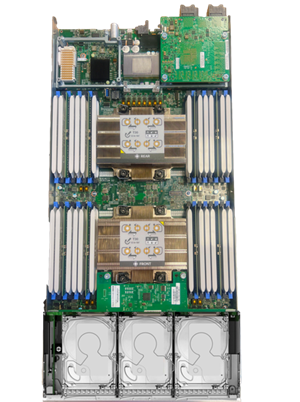
The Cisco UCS X210c M7 features:
● CPU: Up to 2x 4th or 5th Gen Intel Xeon Scalable Processors with up to 64 cores per processor.
● Memory: Up to 32 x 256 GB DDR5-5600 DIMMs for a maximum of 8 TB of main memory.
● Disk storage: Up to 6 SAS or SATA drives or NVMe drives can be configured with the choice of an internal RAID controller or passthrough controllers. Up to two 960GB M.2 memory cards can be added to the Compute Node with optional hardware RAID.
● GPUs: The optional front mezzanine GPU module allows support for up to two HHHL GPUs. Adding a mezzanine card and a Cisco UCS X440p PCIe Node allows up to four more GPUs to be supported with an X210c M7.
● Virtual Interface Card (VIC): Up to 2 VICs including an mLOM Cisco UCS VIC 15230/15231 or an mLOM Cisco UCS VIC 15420 and a mezzanine Cisco UCS VIC card 15422 can be installed in a Compute Node.
● Security: The server supports an optional Trusted Platform Module (TPM). Additional security features include a secure boot FPGA and ACT2 anticounterfeit provisions.
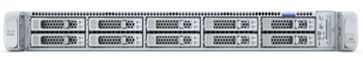
Cisco UCS C220 M7 Rack Server
Cisco UCS Virtual Interface Cards (VICs)
During this validation, following VIC cards were installed in Cisco UCS X210c M7 and Cisco UCS C220 M7 servers:
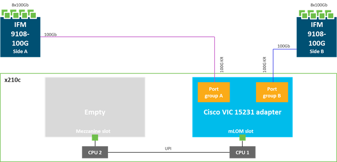
Cisco UCS VIC 15230 and Cisco UCS VIC 15231
Cisco UCS VIC 15230 and15231 fits in the mLOM slot in the Cisco UCS X210c Compute Node and enables up to 100 Gbps of unified fabric connectivity to each of the chassis IFMs for a total of 200 Gbps of connectivity per server. Cisco UCS VIC 15230 is functionally equivalent to Cisco UCS VIC 15231 (used during this validation) but incorporates secure boot technology. Cisco UCS VIC 15230 and 15231 connectivity to the IFM and up to the fabric interconnects is delivered through 100Gbps KR lanes. Cisco UCS VIC 15230 and 15231 supports 512 virtual interfaces (both Fibre Channel and Ethernet) along with the latest networking innovations such as NVMe over fabric, VxLAN/NVGRE offload, and so forth.
Note: Since Cisco UCS VIC 15230 incorporates secure boot technology, for additional security, Cisco UCS VIC 15230 is recommended for Cisco UCS X210c M7 compute nodes.
Cisco UCS VIC 14427 and 15428
The Cisco UCS VIC 15427/15428 is a quad-port small-form-factor pluggable (SFP+/SFP28/SFP56) mLOM card designed for Cisco UCS C-series M6/M7 rack servers. The Cisco UCS VIC 15427 is functionally equivalent to the 15428 (used during this validation) but incorporates secure boot technology. The card supports 10/25/50-Gbps Ethernet or FCoE. The card can present PCIe standards-compliant interfaces to the host, and these can be dynamically configured as either NICs or HBAs. When a UCS rack server with VIC 15427/15428 is connected to a fabric interconnect, the VIC is provisioned through Cisco Intersight™ Managed Mode (IMM) or Cisco UCS Manager (UCSM) policies.
Note: Since Cisco UCS VIC 15427 incorporates secure boot technology, for additional security, Cisco UCS VIC 15427 is recommended for Cisco UCS C-Series M7 rack servers.
Secure Boot mLOM VICs
The Cisco Virtual Interface Card (VIC) 15230 and 15427 provide Secure Boot feature for the rackmount servers Cisco UCS X-Series and Cisco UCS C-Series which significantly enhance the system's security. To protect against tampering through the bootloader code, Cisco VIC employs a Trust Anchor Module (TAM) in its hardware. The TAM serves as a secure component that ensures the integrity of the device's firmware and its boot process. Cisco VIC performs checks on digitally signed images to verify their authenticity. This process ensures that only genuine, unmodified code boots on a Cisco device, significantly reducing the risk of malicious code execution.
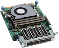
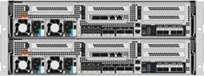
Cisco UCS 6536 Fabric Interconnects
The Cisco UCS Fabric Interconnects (FIs) provide a single point for connectivity and management for the entire Cisco Unified Computing System. Typically deployed as an active/active pair, the system’s FIs integrate all components into a single, highly available management domain controlled by Cisco Intersight or Cisco UCS Manager. Cisco UCS FIs provide low-latency, lossless, cut-through switching that supports LAN, SAN, and management traffic using a single set of cables.
![]()
The Cisco UCS 6536 utilized in the current design is a 36-port Fabric Interconnect. This single RU device includes up to 36 10/25/40/100 Gbps Ethernet ports. Four of these 36 ports (33-36) can be configured to provide 16 8/16/32-Gbps Fibre Channel ports using 128 Gbps to 4x32 Gbps breakouts. All 36 ports support ethernet breakout cables or QSA interfaces.
Cisco UCS Server Security Highlights
Cisco UCS offers a comprehensive security approach that is built into its design from the ground up. Unlike systems where security is an afterthought, with Cisco UCS, every supplier is held to the highest standards, ensuring robust security from the start. Cisco UCS has security controls and policies at every level of infrastructure. These controls provide hardware attestation, integrity, and seamless integration with partner solution security features, offering a secure and reliable computing environment.
Secure Operational Model
In terms of operation, Cisco UCS fits seamlessly into security best practices. It supports multi-factor authentication, single sign-on, and secure APIs, enhancing the system's overall security while providing you with a secure and efficient user experience. Additionally, Cisco UCS reduces the opportunity for malicious or erroneous exposures and alterations by restricting access to sensitive data and controls, ensuring that only authorized individuals can access and modify critical information.
Secure internal and external Communication
Cisco UCS provides customizable, secure, and auditable internal communication. This is achieved using encryption, detailed logging, and ensuring that all communication within the system is secure and traceable. All the external communication between various Cisco UCS components is authenticated, authorized, and uses secure, encrypted traffic and protocols.
UEFI Secure Boot
This validation of FlexPod uses Unified Extensible Firmware Interface (UEFI) Secure Boot. UEFI is a specification that defines a software interface between an operating system and platform firmware. With UEFI secure boot enabled, all executables, such as boot loaders and adapter drivers, are authenticated by the BIOS before they can be loaded.
Trusted Platform Module (TPM)
Cisco UCS compute servers also contain an optional Trusted Platform Module (TPM). VMware ESXi 7.0 U3 supports UEFI Secure Boot and VMware vCenter 7.0 U3 supports UEFI Secure Boot Attestation between the TPM module and ESXi, validating that UEFI Secure Boot has properly taken place.
Digitally Signed redundant Firmware
Cisco UCS firmware images are digitally signed from vendors and secure boot checks the digital signature during boot to allow the firmware update to proceed. Each CIMC, I/O module, BIOS, CIMC, and Cisco adapter has two slots for firmware in flash and each slot holds a version of firmware. One of the slots is active at any time while the other is the backup slot. These components boot from active slot but if the primary software image (in active slot) is breached, the system can be set to boot using the non-active slot and marking the backup firmware as the known good.
Threat Mitigation
Cisco UCS helps increase situational awareness and shorten vulnerability windows through targeted advisories and mitigation automation, allowing for quick and efficient responses to potential threats. This proactive approach to security significantly enhances the system's resilience and reduces the likelihood of successful cyber-attacks.
The Cisco Intersight platform is an infrastructure lifecycle management platform that delivers simplified configuration, deployment, maintenance, and support. The Cisco Intersight platform is designed to be modular, so you can adopt services based on your individual requirements. The platform significantly simplifies IT operations by bridging applications with infrastructure, providing visibility and management from bare-metal servers and hypervisors to serverless applications, thereby reducing costs and mitigating risk. This unified SaaS platform uses an Open API design that natively integrates with third-party platforms and tools. Cisco Intersight offers flexible deployment either as Software as a Service (SaaS) on Intersight.com or running on your premises as Cisco Intersight Virtual Appliance.
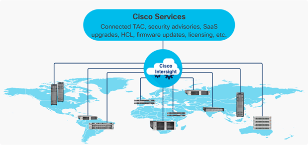
The main benefits of Cisco Intersight infrastructure services are as follows:
● Simplify daily operations by automating many daily manual tasks.
● Combine the convenience of a SaaS platform with the capability to connect from anywhere and manage infrastructure through a browser or mobile app.
● Stay ahead of problems and accelerate trouble resolution through advanced support capabilities.
● Gain global visibility of infrastructure health and status along with advanced management and support capabilities.
● Upgrade to add workload optimization services when needed.
Cisco Intersight Virtual Appliance and Private Virtual Appliance
In addition to the SaaS deployment model running on Intersight.com, on-premises options can be purchased separately. The Cisco Intersight Virtual Appliance and Cisco Intersight Private Virtual Appliance are available for organizations that have additional data locality or security requirements for managing systems. The Cisco Intersight Virtual Appliance delivers the management features of the Cisco Intersight platform in an easy-to-deploy VMware Open Virtualization Appliance (OVA) or Microsoft Hyper-V Server virtual machine that allows you to control the system details that leave your premises. The Cisco Intersight Private Virtual Appliance is provided in a form factor specifically designed for those who operate in disconnected (air gap) environments. The Private Virtual Appliance requires no connection to public networks or back to Cisco to operate.
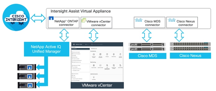
Cisco Intersight Assist
Cisco Intersight Assist helps you add endpoint devices to Cisco Intersight. A data center could have multiple devices that do not connect directly with Cisco Intersight. Any device that is supported by Cisco Intersight, but does not connect directly with it, will need a connection mechanism. Cisco Intersight Assist provides that connection mechanism. In FlexPod, VMware vCenter and NetApp Active IQ Unified Manager, Cisco Nexus, and Cisco MDS switches (if deployed) connect to Intersight with the help of Intersight Assist VM.
Cisco Intersight Assist is available within the Cisco Intersight Virtual Appliance, which is distributed as a deployable virtual machine contained within an Open Virtual Appliance (OVA) file format. A single Cisco Intersight Assist virtual appliance can support NetApp ONTAP storage, VMware vCenter, and Cisco switches.
Licensing Requirements
The Cisco Intersight platform uses a subscription-based license with multiple tiers. You can purchase a subscription duration of one, three, or five years and choose the required Cisco UCS server volume tier for the selected subscription duration. Each Cisco endpoint automatically includes a Cisco Intersight Base license at no additional cost when you access the Cisco Intersight portal and claim a device. You can purchase any of the following higher-tier Cisco Intersight licenses using the Cisco ordering tool:
● Cisco Intersight Essentials: the Essentials includes Lifecycle Operations features, including Cisco UCS Central and Cisco UCS-Manager entitlements, policy-based configuration with server profiles (IMM), firmware management, Global Monitoring and Inventory, Custom Dashboards, and evaluation of compatibility with the Cisco Hardware Compatibility List (HCL). Also, Essentials includes Proactive Support features, including Proactive RMA, Connected TAC, Advisories, and Sustainability.
● Cisco Intersight Advantage: Advantage offers all the features of the Essentials tier plus In-Platform Automation features such as Tunneled KVM, Operating System Install Automation, Storage/Virtualization/Network Automation, and Workflow Designer. It also includes Ecosystem Integrations for Ecosystem Visibility, Operations, and Automation, and ServiceNow Integration.
Servers in the Cisco Intersight managed mode require at least the Essentials license. For detailed information about the features provided in the various licensing tiers, see: https://intersight.com/help/saas/getting_started/licensing_requirements/lic_infra.
Cisco Intersight Assist Device Connector for VMware vCenter, NetApp ONTAP, Cisco Nexus, and Cisco MDS Switches
Cisco Intersight integration with VMware vCenter, NetApp ONTAP, and Cisco switches enables you to perform the following tasks right from the Intersight dashboard:
● Monitor the virtualization, storage, and switching environment.
● Add various dashboard widgets to obtain useful at-a-glance information.
● Perform common Virtual Machine tasks such as power on/off, remote console and so on.
● Orchestrate virtual, storage, and switching, environment to perform common configuration tasks.
● Define FlexPod as an Intersight Integrated System to view various system properties such as capacity, usage, physical and virtual components, and Interoperability status of various devices using Interoperability Matrix Tool (IMT).
Since Cisco Intersight is a SaaS platform, the monitoring and orchestration capabilities are constantly being added and delivered seamlessly from the cloud. Cisco Intersight integrates with VMware vCenter, NetApp storage and Cisco Nexus and MDS switches as follows:
● Cisco Intersight uses the device connector running within Cisco Intersight Assist virtual appliance to communicate with the VMware vCenter.
● Cisco Intersight uses the device connector running within a Cisco Intersight Assist virtual appliance to integrate with NetApp Active IQ Unified Manager. The NetApp AFF A400 should be added to NetApp Active IQ Unified Manager.
● Cisco Intersight uses the device connector running within the Cisco Intersight Assist virtual appliance to communicate with Cisco Nexus 9000 and MDS switches.
The device connector provides a secure way for connected targets to send information and receive control instructions from the Cisco Intersight portal using a secure internet connection. The integration brings the full value and simplicity of Cisco Intersight infrastructure management service to VMware hypervisor and ONTAP data storage environments.
Key Security Highlights
The layered security architecture of Cisco Intersight incorporates several key elements to ensure maximum protection. The architecture includes the use of industry-standard protocols (such as HTTPS) to provide secure communication and during transport all data is encrypted, ensuring confidentiality, and preventing unauthorized access. A clear separation is maintained between the management and production networks to eliminate any potential interference. In the Intersight architecture, no production network data flows to or from Intersight, adding another layer of safety. The system identifies, authenticates, and authorizes all devices during the claim process as well as all subsequent transfers, ensuring secure transactions. Furthermore, all management tasks are driven by the device itself, eliminating the need for device inbound connections.
Access and Authentication
Cisco Intersight accounts form the authentication domain for users. The accounts control all resource access, and authenticated users are restricted from seeing any data in accounts where they are not authorized. With the SaaS platform, Cisco login IDs can be used for authentication with the identity provider for Cisco.com, which includes support for multifactor authentication. Both SaaS and on-premises Intersight implementations allow integration with external identity management systems to meet existing customer authentication requirements. The Cisco Intersight framework uses granular access control with privileges managed per resource. Intersight software allows configuration of users and groups into several roles, and each user or group can be a member of multiple roles.
Role Based Access Control
Resource Groups in Cisco Intersight comprise of a collection of managed resources or targets, providing a structured and organized system for managing different assets. In this system, organizations play a crucial role in enabling multi-tenancy by placing devices into logically separated resource groups. This separation facilitates effective management and control over different resources. Access control in Cisco Intersight is fundamentally underpinned by roles and privileges where roles are tied to a specific set of privileges to perform operations related to that role to ensure that every user has defined responsibilities and access rights, enhancing system security and efficiency. The privileges in Cisco Intersight can be based on specific areas of responsibility, such as UCS Domain, Virtualization, Storage, and Network. Each area requires a particular skill set and understanding, and by associating privileges with specific roles, you can ensure that the most qualified personnel handle tasks. This enhances the operational efficiency and security of the system.
Policy Driven Control
Cisco Intersight and Cisco UCS Manager deliver significant advantages through policy-driven control plane. Using server profile templates associated with several policies, UCS server deployments support physical and logical abstraction. This abstraction of physical resources ensures hardware identifies stay secured (hidden) during deployment and the system remains protected and robust, capable of fending off potential threats by quickly creating new server profiles and identities to replace the compromised servers.
Using server profile templates, Cisco Intersight associates repeatable secure baselines to physical servers. This allows for the standardization of security measures across various systems, thereby bolstering overall security and reducing potential vulnerabilities. Additionally, Cisco Intersight provides a centralized add/change/delete functionality. This centralized control not only simplifies system management but also significantly reduces the audit footprint. By consolidating all changes in one place, tracking, reviewing, and auditing changes become much more manageable and efficient.
Cisco Intersight also offers drift protection as part of its deployment design. Drift protection ensures that system configurations remain consistent over time. It automatically identifies (and sometimes rectifies) any deviations from the defined configurations, thereby maintaining system security and optimal performance levels.
Endpoint Security Advisories
Cisco's Intersight platform serves as a comprehensive tool for managing security advisories. It is equipped to display devices that are impacted by Cisco Security Advisories, ensuring users are aware of potential vulnerabilities or threats. These advisories are conveniently available in the menu bar of the user interface, making them easily accessible for users. Each advisory comes with associated Common Vulnerabilities and Exposures (CVE) IDs and links to more detailed information. This feature allows users to explore the nature of the security advisories in more detail, enabling them to understand the potential impact and implement necessary mitigation strategies.
Cisco Nexus 93600CD-GX Ethernet Switch
The Cisco Nexus 9000 series switch featured in this design is the Cisco Nexus 93600CD-GX configured in NX-OS standalone mode. NX-OS is a purpose-built data-center operating system designed for performance, resiliency, scalability, manageability, and programmability at its foundation. It provides a robust and comprehensive feature set that meets the demanding requirements of virtualization and automation.
![]()
The Cisco Nexus 93600CD-GX Switch is a 1RU switch that supports 12 Tbps of bandwidth and 4.0 bpps. The 28 downlink ports on the 93600CD-GX support 40/100-Gbps Ethernet, offering deployment flexibility and investment protection. The eight uplink ports can be configured as 10/25/40/50/100/200/400-Gbps Ethernet using appropriate optics and breakout cables, offering flexible migration options.
Note: For detailed information in port speeds and breakout options, refer to: https://www.cisco.com/c/en/us/td/docs/switches/datacenter/nexus9000/hw/n93600cd-gx-hig/guide/b_c93600cd-gx-nxos-mode-hardware-installation-guide/m_overview1.html
NetApp AFF A-Series controller lineup provides industry leading performance while continuing to provide a full suite of enterprise-grade data services for a shared environment across on-premises data centers and the cloud. Powered by NetApp ONTAP data management software, NetApp AFF A-Series systems deliver the industry’s highest performance, superior flexibility, and best-in-class data services and cloud integration to help you accelerate, manage, and protect business-critical data on-prem and across hybrid clouds. As the first enterprise-grade storage systems to support both NVMe over Fibre Channel (NVMe/FC) and NVMe over TCP (NVMe/TCP), AFF A-Series systems boost performance with modern network connectivity. These systems deliver the industry’s lowest latency for an enterprise all-flash array, making them a superior choice for running the most demanding workloads and applications. With a simple software upgrade to the modern NVMe/FC or NVMe/TCP SAN infrastructure, you can run more workloads, with faster response times, and without disruption or data migration.
NetApp offers a wide range of AFF-A series controllers to meet varying demands of the field. This solution design details midrange, the most versatile NetApp AFF A400 system featuring hardware acceleration technology that significantly enhances performance and storage efficiency.
For more information about the NetApp AFF A-series controllers, see the AFF product page: https://www.netapp.com/us/products/storage-systems/all-flash-array/aff-a-series.aspx.
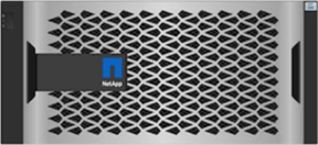
NetApp AFF A400
The NetApp AFF A400 offers full end-to-end NVMe support. The frontend NVMe/FC connectivity makes it possible to achieve optimal performance from an all-flash array for workloads that include artificial intelligence, machine learning, and real-time analytics as well as business-critical databases. On the back end, the A400 supports both serial-attached SCSI (SAS) and NVMe-attached SSDs, offering the versatility for current customers to move up from their legacy A-Series systems and satisfying the increasing interest that all customers have in NVMe-based storage.
The NetApp AFF A400 offers greater port availability, network connectivity, and expandability. The NetApp AFF A400 has 10 PCIe Gen3 slots per high availability pair. The NetApp AFF A400 offers 25GbE or 100GbE, as well as 32Gb/FC and NVMe/FC network connectivity. This model was created to keep up with changing business needs and performance and workload requirements by merging the latest technology for data acceleration and ultra-low latency in an end-to-end NVMe storage system.
Note: Cisco UCS X-Series is supported with all NetApp AFF systems running NetApp ONTAP 9 release.
NetApp ONTAP 9.13.1
NetApp storage systems harness the power of ONTAP to simplify the data infrastructure from edge, core, and cloud with a common set of data services and 99.9999 percent availability. NetApp ONTAP 9 data management software from NetApp enables you to modernize your infrastructure and transition to a cloud-ready data center. ONTAP 9 has a host of features to simplify deployment and data management, accelerate and protect critical data, and make infrastructure future-ready across hybrid-cloud architectures.
NetApp ONTAP 9 is the data management software that is used with the NetApp AFF A400 all-flash storage system in this solution design. ONTAP software offers secure unified storage for applications that read and write data over block- or file-access protocol storage configurations. These storage configurations range from high-speed flash to lower-priced spinning media or cloud-based object storage. ONTAP implementations can run on NetApp engineered FAS, AFF, or ASA series arrays and in private, public, or hybrid clouds (NetApp Private Storage and NetApp Cloud Volumes ONTAP). Specialized implementations offer best-in-class converged infrastructure, featured here as part of the FlexPod Datacenter solution or with access to third-party storage arrays (NetApp FlexArray virtualization). Together these implementations form the basic framework of the NetApp Data Fabric, with a common software-defined approach to data management, and fast efficient replication across systems. FlexPod and ONTAP architectures can serve as the foundation for both hybrid cloud and private cloud designs.
Read more about all the capabilities of ONTAP data management software here: https://www.netapp.com/us/products/data-management-software/ontap.aspx.
See the ONTAP 9 release notes for more details on specific features and what’s new: ONTAP 9 Release Notes (netapp.com)
NetApp Active IQ Unified Manager
NetApp Active IQ Unified Manager is a comprehensive monitoring and proactive management tool for NetApp ONTAP systems to help manage the availability, capacity, protection, and performance risks of the storage systems and virtual infrastructure. The Unified Manager can be deployed on a Linux server, a Windows server, or as a virtual appliance on a VMware host.
Active IQ Unified Manager enables monitoring ONTAP storage clusters from a single redesigned, intuitive interface that delivers intelligence from community wisdom and AI analytics. It provides comprehensive operational, performance, and proactive insights into the storage environment and the virtual machines running on it. When an issue occurs on the storage infrastructure, Unified Manager can notify storage admins about the details of the issue to help identify the root cause. The virtual machine dashboard provides performance statistics for the VM so that users can investigate the entire I/O path from the vSphere host down through the network and finally to the storage. Some events also provide remedial actions that can be taken to rectify the issue. Custom alerts can be configured for events so that when issues occur, notifications are sent via email or using SNMP Traps. Active IQ Unified Manager enables planning for the storage requirements by forecasting capacity and usage trends to proactively act before issues arise.
For more information on NetApp Active IQ Unified Manager, refer to the following link: https://docs.netapp.com/us-en/active-iq-unified-manager/
NetApp ONTAP Tools for VMware vSphere
The ONTAP tools for VMware vSphere provide end-to-end life cycle management for virtual machines in VMware environments that use NetApp storage systems. It simplifies storage and data management by enabling administrators to directly manage storage within the vCenter Server.
Note: Each component in ONTAP tools provides capabilities to help manage storage more efficiently.
Virtual Storage Console (VSC)
NetApp Virtual Storage Console enables you to perform the following tasks:
● Add storage controllers, assign credentials, and set up permissions for storage controllers.
● Provision datastores.
● Monitor the performance of the datastores and virtual machines in the vCenter Server environment.
● View and update the host settings of the ESXi hosts that are connected to NetApp storage.
● Control administrator access to the vCenter Server objects by using role-based access control (RBAC).
VASA Provider
VASA Provider for NetApp ONTAP uses VMware vSphere APIs for Storage Awareness (VASA) to send information about storage used by VMware vSphere to the vCenter Server. NetApp ONTAP tools has VASA Provider integrated with VSC. VASA Provider enables you to perform the following tasks:
● Provision VMware Virtual Volumes (vVols) datastores.
● Create and use storage capability profiles that define different storage service level objectives (SLOs) for your environment.
● Verify for compliance between the datastores and the storage capability profiles.
● Set alarms to warn you when volumes and aggregates are approaching the threshold limits.
● Monitor the performance of virtual machine disks (VMDKs) and the virtual machines that are created on vVols datastores.
Storage Replication Adapter (SRA)
SRA enables you to use array-based replication (ABR) for protected sites and recovery sites for disaster recovery in the event of a failure. When SRA is enabled and used in conjunction with VMware Site Recovery Manager (SRM), you can recover the vCenter Server datastores and virtual machines in the event of a failure.
NetApp SnapCenter
SnapCenter Software is a simple, centralized, scalable platform that provides application consistent data protection for applications, databases, host file systems, and VMs running on NetApp ONTAP systems anywhere on premise or in the Hybrid Cloud.
SnapCenter leverages NetApp Snapshot, SnapRestore, FlexClone, SnapMirror, and SnapVault technologies to provide:
● Fast, space-efficient, application-consistent, disk-based backups.
● Rapid, granular restore, and application-consistent recovery.
● Quick, space-efficient cloning.
SnapCenter includes both SnapCenter Server and individual lightweight plug-ins. You can automate deployment of plug-ins to remote application hosts, schedule backup, verification, and clone operations, and monitor all data protection operations. Data protection is supported for Microsoft Exchange Server, Microsoft SQL Server, Oracle Databases on Linux or AIX, SAP HANA database, and Windows Host Filesystems running on NetApp ONTAP systems. It is also supported for other standard or custom applications and databases by providing a framework to create user-defined SnapCenter plug-ins. You may install only the plug-ins that are appropriate for the data that you want to protect.
Note: For more information on SnapCenter, refer to the SnapCenter software documentation: https://docs.netapp.com/us-en/snapcenter/index.html
NetApp BlueXP
NetApp BlueXP is a unified control plane that provides a hybrid multi-cloud experience for storage and data services across on-premises and cloud environments. NetApp BlueXP is an evolution of Cloud Manager and enables the management of your NetApp storage and data assets from a single interface. NetApp BlueXP is used to move, protect, and analyze data, and to control on-prem storage devices like NetApp ONTAP, E-Series, and StorgeGRID, and to create and administer cloud storage (for example, Cloud Volumes ONTAP and Azure NetApp Files).
The NetApp BlueXP backup and recovery service provides efficient, secure, and cost-effective data protection for NetApp ONTAP data, Kubernetes persistent volumes, databases, and virtual machines, both on premises and in the cloud. Backups are automatically generated and stored in an object store in public or private cloud account. NetApp BlueXP ransomware protection provides a single point of visibility and control to manage and to refine data security across various working environments and infrastructure layers to better respond to threats as they occur.
Note: For more information on NetApp BlueXP, go to: https://docs.netapp.com/us-en/cloud-manager-family/
vSphere uses virtualization to transform individual data centers into aggregated computing infrastructures that include CPU, storage, and networking resources. VMware vSphere manages these infrastructures as a unified operating environment and provides you with the tools to administer your data centers that participate in that environment. The two core components of VMware vSphere are ESXi and vCenter Server. ESXi is the virtualization platform which allows you to create and run virtual machines and virtual appliances. vCenter Server is the service through which virtualization administrators manage multiple hosts.
Latest FlexPod infrastructure validated design supports vSphere 8.0 but currently, Cisco Firewall Threat Defense (FTDv) is not supported on VMware ESXi 8.0. Since FTDv is installed on the FlexPod infrastructure being validated, VMware vSphere 7.0 U3 was selected during this validation.
Note: If you are deploying physical FTD devices or are using an existing (separate) VMware vSphere 7.0 based management infrastructure to deploy FTDv, VMware vSphere 8.0 can be used on the FlexPod infrastructure to deploy applications.
VMware vSphere 7.0 U3
VMware vSphere is a virtualization platform for holistically managing large collections of infrastructures (resources including CPUs, storage, and networking) as a seamless, versatile, and dynamic operating environment. Unlike traditional operating systems that manage an individual machine, VMware vSphere aggregates the infrastructure of an entire data center to create a single powerhouse with resources that can be allocated quickly and dynamically to any application in need.
VMware vSphere 7.0 U3 has several improvements and simplifications including, but not limited to:
● Support for the NVMe-TCP storage protocol with VMFS6 datastores.
● Improvements to vSphere Cluster Services (vCLS), including the ability to designate a datastore to store vCLS virtual machines.
● Improved Maintenance Mode Reliability and Workload Placement.
● Enhanced Performance Statistics for Memory.
● vSphere Lifecycle Management (vLCM) with Hardware Support Manager (HSM) Integration with Cisco Intersight.
● A VMware-Recommended 128GB SAN boot LUN for VMware ESXi.
For more information about VMware vSphere and its components, see: https://www.vmware.com/products/vsphere.html.
VMware vSphere vCenter
VMware vCenter Server provides unified management of all hosts and VMs from a single console and aggregates performance monitoring of clusters, hosts, and VMs. VMware vCenter Server gives administrators a deep insight into the status and configuration of compute clusters, hosts, VMs, storage, the guest OS, and other critical components of a virtual infrastructure. VMware vCenter manages the rich set of features available in a VMware vSphere environment.
Infrastructure as Code with Ansible
This FlexPod solution provides a fully automated solution deployment that covers all components of the infrastructure. The configuration of the Cisco Network and Compute, NetApp ONTAP Storage, and VMware vSphere are automated by leveraging Ansible playbooks that have been developed to setup the components according to the solution best practices. The automated deployment using Ansible provides a well-defined sequence of steps across the different elements of this solution. The automated deployment involves exchange of parameters or attributes between compute, network, storage, and virtualization and require some level of manual intervention. The workflow is clearly defined and documented. The Ansible playbooks to configure the different sections of the solution invoke a set of Roles which consume several user configurable variables. Based on the installation environment, you can choose to modify the variables to suit your needs and proceed with the automated installation.
After the FlexPod infrastructure is setup, NetApp Management Tools such as ONTAP Tools for VMware vSphere (formerly Virtual Storage Console), SnapCenter Plug-in for VMware vSphere, and Active IQ Unified Manager can also be deployed in an automated fashion.
Today, attacks like phishing, ransomware, and advanced persistent threats are common. No single product can successfully secure a business from these risks. An architectural approach that addresses the full range from people, to devices, to applications is needed. Secure Architecture for Everyone (SAFE) can help simplify security strategy and deployment. This Cisco security reference architecture features easy-to-use visual icons that helps you design a secure infrastructure for the edge, branch, data center, campus, cloud, and WAN. The framework encompasses operational domains such as management, security intelligence, compliance, segmentation, threat defense, and secure services. SAFE solutions have been deployed, tested, and validated at Cisco and provide guidance, best practices, and configuration steps.
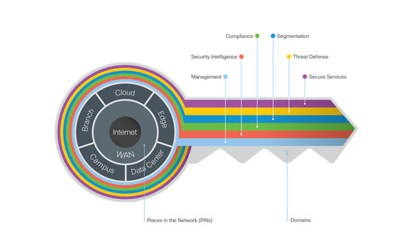
The Key to SAFE provides the Key to simplify cybersecurity into Secure Places in the Network (PINs) for infrastructure and Secure Domains for operational guidance. SAFE includes:
● Business use cases illustrating the surface that fraudsters can attack.
● Security capabilities mapped to common threats within business use cases.
● Reference architectures that logically arrange the security capabilities into blueprints.
● Designs using the reference architectures for common deployment scenarios and solutions delivered as Cisco Validated Designs (CVDs).
Zero Trust Framework for FlexPod
Zero Trust framework for FlexPod validated design aligns with the Cisco SAFE architecture guidelines for Data Center. Various capabilities are necessary to protect the workloads running on FlexPod Datacenter and to build appropriate layers of defense that protect your applications.
Three (of several) core pillars of Zero Trust framework explained in this design guide are:
● Segmentation - Reduce the attack surface by preventing attackers from moving laterally, with consistent security policy enforcement, application access control and micro segmentation.
● Visibility - Complete visibility of users, devices, networks, applications, workloads, and processes.
● Threat Protection - Stop the breach by quickly detecting, blocking, and dynamically responding to threats.
These Cisco security products and solutions are deployed to satisfy the requirements:
● Cisco Secure Firewall Threat Defense – for enforcing traffic control and segmentation.
● Cisco Secure Network Analytics – for network traffic visibility and anomaly detection.
● Cisco Secure Workload – for device and process level visibility and threat mitigation
For more details on Cisco SAFE architecture and validated designs, refer to: https://www.cisco.com/c/en/us/solutions/enterprise/design-zone-security/landing_safe.html.
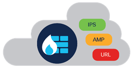
Cisco Secure Firewall Threat Defense Virtual
Cisco Secure Firewall Threat Defense Virtual (FTDv) combines Cisco's proven next-generation firewall (NGFW) technology with threat defense features like Snort intrusion prevention system (IPS), URL filtering, and Advanced Malware Protection (AMP). It simplifies threat protection with consistent security policies across physical, private, and public cloud environments.
Cisco Secure Firewall Threat Defense - Key Features
● Stateful firewall: Inspects traffic at both the Layer 3 and Layer 4 levels to detect and block unauthorized traffic.
● Intrusion prevention system (IPS): Protects against known and unknown attacks using Snort technology.
● URL filtering: Blocks access to malicious websites and other unwanted content.
● Advanced Malware Protection: Detects and blocks malware before it can infect your systems.
● Application visibility and control: Provides granular control over applications and their traffic.
● Threat intelligence: Provides real-time updates about the latest threats.
Cisco Secure Firewall Threat Defense - Key Benefits
● Simplified security management: Deploy and manage your firewall from a single pane of glass, with unified policy and consistent enforcement across all your environments.
● Flexibility: Deploy the firewall anywhere you need it, whether it's in your data center, public cloud, or private cloud.
● Scalability: Easily scale your firewall up or down to meet your changing needs.
● Comprehensive security: Get protection from a wide range of threats, including malware, phishing, and botnets.
● Integration with other Cisco security solutions: Integrate Threat Defense Virtual with other Cisco security solutions, such as SecureX and Umbrella, to create a comprehensive security posture.
For more details: https://www.cisco.com/c/en/us/products/collateral/security/firepower-ngfw-virtual/threat-defense-virtual-ngfwv-ds.html
Cisco Secure Firewall Management Center
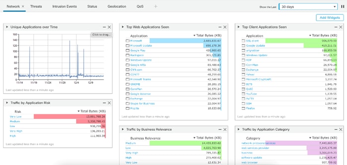
The Cisco Secure Firewall Management Center (FMC) provides complete and unified management of firewalls, application control, intrusion prevention, URL filtering, and advanced malware protection. It is a key part of the broad Cisco Secure portfolio, delivering in-depth analysis, streamlined security management across the network and cloud, and accelerated incident investigation and response, working across your Cisco and third-party technologies. FMC is ideal for organizations with large deployments of Cisco Secure firewalls, as it simplifies management and reduces operational costs.
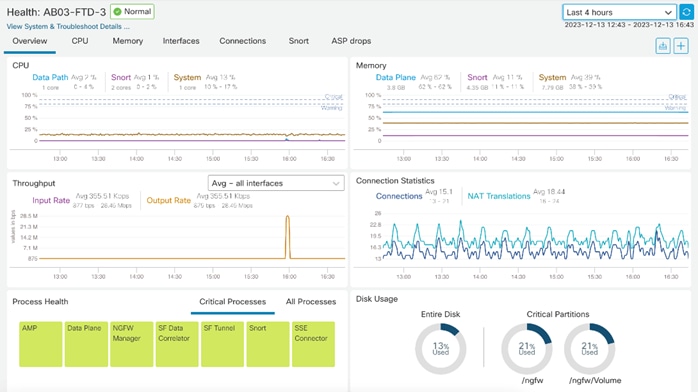
The Firewall Management Center (FMC) provides contextual network and security information so you can make quick and informed decisions. See Figure 18.
FMC also provides real-time device health monitoring and status across multiple devices. See Figure 19.
Cisco Secure Firewall Management Center - Key Features
● Policy management: Create and manage firewall policies with a drag-and-drop interface.
● Object management: Manage objects, such as networks, addresses, and users, in a central location.
● Configuration management: Manage firewall configurations and settings from a single console.
● Monitoring and reporting: Monitor security events and traffic in real time and generate reports to track trends and identify security issues.
● Threat intelligence integration: Integrate with Cisco Talos to receive threat intelligence updates and automatically generate policies to protect against the latest threats.
Cisco Secure Firewall Management Center - Key Benefits
● Centralized management: Manage all your Cisco Secure firewalls from a single console, simplifying security administration and reducing operational costs. Multitenancy management and policy inheritance by creating up to 100 management domains.
● Automated workflows: Automate repetitive tasks, such as configuration changes and policy updates, to improve efficiency and reduce errors.
● Open APIs: Integrate with third-party technologies through powerful APIs.
● Real-time visibility: Get real-time visibility into your security posture with dashboards and reports that provide insights into traffic, threats, and events.
● Scalability: Manage large deployments of Cisco Secure firewalls with ease.
FMC is preferred method of managing multiple firewalls in Zero Trust framework for FlexPod design. For more details: https://www.cisco.com/c/en/us/products/collateral/security/firesight-management-center/datasheet-c78-736775.html
Cisco Secure Network Analytics
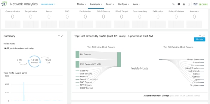
Cisco Secure Network Analytics (formerly known as Stealthwatch) is a comprehensive network traffic analysis (NTA) and network detection and response (NDR) solution that uses telemetry from the existing network infrastructure to provide deep visibility into network activity and detect threats across private networks, public clouds, and even encrypted traffic.
The solution continuously analyzes network activities to create a baseline of normal network behavior. It then uses this baseline, along with non–signature-based advanced analytics that include behavioral modeling and machine learning algorithms, as well as global threat intelligence to identify anomalies and detect and respond to threats in real-time. Secure Network Analytics can quickly and with high confidence detect threats such as Command-and-Control (C&C) attacks, ransomware, Distributed-Denial-of-Service (DDoS) attacks, illicit crypto mining, unknown malware, and insider threats. With an agentless solution, you get comprehensive threat monitoring across the entire network traffic, even if it’s encrypted.
Cisco Secure Network Analytics performs monitoring of network traffic using data collected from NetFlow devices across the network acting as a complement to the string based IPS detection of Secure Firewall.
Cisco Secure Network Analytics key features
● Traffic analysis: Analyzes network traffic to identify applications, users, and devices.
● Threat detection: Uses machine learning and behavioral analysis to detect threats in real-time.
● Incident investigation: Provides tools to investigate security incidents quickly and efficiently.
● Security automation: Automates security tasks, such as incident response and threat hunting.
● Advanced reporting: Provides detailed reports on network activity, threats, and compliance.
Required Components of the System
Manager
The Secure Network Analytics Manager aggregates, organizes, and presents analyses from up to 25 Flow Collectors, Cisco Secure Network Access (formerly Cisco Identity Services Engine), and other sources. It uses graphical representations of network traffic, identity information, customized summary reports, and integrated security and network intelligence for comprehensive analysis. Secure Network Analytics Manager provides graphical views of the current state of the organization’s traffic. Administrators can easily construct maps of their network based on any criteria, such as location, function, or virtual environment.
Flow Collector
The Flow Collector collects and stores enterprise telemetry types such as NetFlow from existing infrastructure such as routers, switches, firewalls, endpoints, and other network infrastructure devices. The Flow Collector can also collect telemetry from proxy data sources, which can be analyzed by the cloud-based machine learning engine (global threat alerts). The telemetry data is analyzed to provide a complete picture of network activity. Months or even years of data can be stored, creating an audit trail that can be used to improve forensic investigations and compliance initiatives.
Data Store (optional)
The Data Store provides a solution for environments requiring high data ingest capacity levels or long-term retention times that exceed the capacity of one or more Flow Collectors. The Data Store cluster can be added between the Secure Network Analytics Manager and Flow Collectors. For these larger and more extensive networks, one or more Flow Collectors ingest and de-duplicate flow data, perform analyses, and then send the flow data and its results directly to the Data Store.
In this guide, Secure Network Analytics is deployed as two devices, a Flow Collector virtual machine and a Management Center virtual machine. For more information, go to: https://www.cisco.com/c/en/us/products/collateral/security/stealthwatch/datasheet-c78-739398.html
Cisco Secure Workload (formerly known as Cisco Tetration) is a comprehensive security platform that helps you achieve micro-segmentation and implement a zero-trust security model across their entire application landscape, regardless of location or workload type. Cisco Secure Workload offers a unified view of network, applications, and workloads, enabling you to detect and respond to threats quickly and effectively.
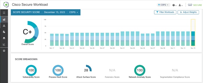
Cisco Secure Workload has a SaaS offering that provides the capability to do micro-segmentation in a highly flexible manner along with an in-depth visibility into the workloads. Cisco Secure Workload offers visibility and enforcement agents that are installed on the workloads. The enforcement agents provide an additional capability to enforce policies. Cisco Secure Workload can dynamically learn various ongoing changes in the cloud workload environment and enforce an adaptive micro-segmentation and the user portal allows you to create workspaces and graphical views for applications and enforce security from the web application point of view. Once the agent on the new workload is registered with the Cisco Secure Workload, it starts exporting the network flow and process information for analysis.
Cisco Secure Workload Key Features
Cisco Secure Workload ensures Cisco's Zero Trust model with the following key features:
● Policy enforcement (Micro-segmentation).
● Visibility into workload process activity.
● Network flow visibility.
● Software vulnerability reports.
● Forensic analysis.
● Behavior deviations.
Cisco Secure Workload Deployment Options
Cisco Secure Workload offers two deployment options: on-premises and SaaS.
The on-premises option is a hardware-based appliance that comes in two sizes: small and large. It is suitable for any business type and size, and it offers high performance, high availability, and on-premises control of apps and data.
The SaaS option is a fully managed service that is suitable for any size customer. It has a low barrier to entry and a flexible pricing model, and it enables secure migration to cloud and multi-cloud environments.
In this guide, Secure Workload SaaS is utilized. For more information, go to: https://www.cisco.com/site/us/en/products/security/secure-workload/index.html#tabs-ca9b217826-item-9e6cde6a19-tab
Intel Confidential Computing is a security technology built into Intel processors that enables protected execution of sensitive data within a hardware-isolated environment called a Trusted Execution Environment (TEE). This TEE acts as a secure enclave, shielding data and computations from unauthorized access, even from privileged software like the operating system or the hypervisor.
Enterprise services often run in a hybrid and multi-cloud environment, and it is critical to protect enterprise applications when working with confidential data such as username, password, database credentials, and API keys, when interacting with third-party services, credentials for service-oriented architecture communication, and more. Intel’s Xeon Scalable processor has multiple security features that can help significantly boost the security posture of a Zero Trust solution architecture, including Intel Total Memory Encryption (Intel TME) for memory encryption and Intel Software Guard Extensions (Intel SGX) facilitating confidential computing.
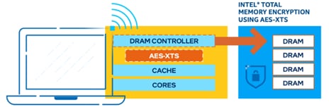
Intel Total Memory Encryption (Intel TME)
Intel TME can encrypt the entirety of physical memory of a physical server system. This capability typically is enabled in the very early stages of the boot process with a small setting in the UEFI/BIOS. After it is configured and locked, the CPU is responsible for encrypting all data into the system memory. Intel TME is based on the National Institute of Standards and Technology (NIST) standard AES-XTS algorithm with 128-bit or 256-bit keys, depending on the algorithm availability and selection. The encryption key used for Intel TME uses a hardware random number generator implemented in the Intel CPU, and the key is not accessible by software or with external interfaces. The AES-XTS encryption engine is in the direct data path to external memory buses and, therefore, all the memory data entering and/or leaving the CPU on memory buses is encrypted using AES-XTS. A Key for Intel TME is generated at every boot time. If the system is resuming from a standby, Intel TME can restore the key from storage.
Intel TME capability is transparent to software such as operating systems, hypervisors, or containers, applications, and micro services. It does not require any specific Linux kernel support. Overall, the performance impact of this capability is almost negligible when running software workloads such as Vault.
Intel Software Guard Extensions (Intel SGX)
Intel SGX is a set of instructions incorporated in Intel Xeon Scalable processor. Software developers can place security-sensitive codes and data into an Intel SGX enclave, which is then executed in a CPU protected region. Traditionally, when a system’s BIOS, hypervisor, or operating system is compromised by a malicious attack, the attacker’s code can gain visibility and access to everything higher in the system stack, such as applications and data. Intel SGX utilizes memory encryption and hardware-enforced access controls to change how data is accessed, providing enclaves of protected memory in which to run applications and data. Secure enclaves can be created on untrusted platforms not owned by the enterprise. Intel processor-based attestation can ensure the integrity of a secure enclave. After the enclave is verified, the remote attestation (application) can push secrets securely into the enclave. Even if the system is hosted in a third-party facility such as cloud, edge, or POP, the application can rely on Intel SGX to help secure the data and reduce the attacking surface available, such as to inside hackers or misconfiguration.
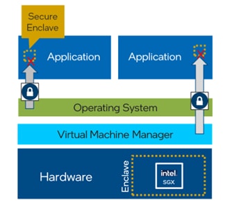
Intel SGX currently provides the smallest trust boundary in data center confidential computing, compared to other confidential computing technologies. With Intel SGX, only the code or functions inside the protected enclave can access confidential data.
For further details of Intel Confidential Computing, go to: https://www.intel.com/content/www/us/en/security/confidential-computing.html.
Secure Virtual Machines with Intel SGX
VMware vSphere enables you to configure Virtual Intel Software Guard Extensions (vSGX) for virtual machines. vSGX enables virtual machines to use Intel SGX technology if available on the hardware. To use vSGX, the ESXi host must be installed on an SGX-capable CPU such as Intel Xeon scalable processor and SGX must be enabled in the BIOS of the ESXi host. The VMware vSphere Client can then be used to enable SGX for a virtual machine.
NetApp Security and Ransomware Protection
NetApp Autonomous Ransomware Protection (ARP) takes a proactive and automated approach to safeguarding your data from the ever-evolving threat of ransomware attacks. Beginning with ONTAP 9.10.1, the Autonomous Ransomware Protection (ARP) feature uses workload analysis in NAS (NFS and SMB) environments to proactively detect and warn about abnormal activity that might indicate a ransomware attack. When an attack is suspected, ARP also creates new Snapshot copies, in addition to existing protection from scheduled Snapshot copies. ARP offers anti-ransomware detection based on:
● Identification of the incoming data as encrypted or plaintext.
● Analytics, which detects:
◦ Entropy: an evaluation of the randomness of data in a file.
◦ File extension types: An extension that does not conform to the normal extension type.
◦ File IOPS: A surge in abnormal volume activity with data encryption.
ARP can detect the spread of most ransomware attacks after only a small number of files are encrypted, act automatically to protect data, and alert admins that a suspected attack is happening.
NetApp Autonomous Ransomware Protection Key Benefits
● Reduced risk of data loss: Proactive and automated intervention minimizes the potential damage from ransomware attacks.
● Faster recovery times: Quick identification and isolation of threats enable swift restoration of affected data.
● Simplified security management: ARP automates many security tasks, freeing up IT teams to focus on strategic initiatives.
● Improved security posture: The multi-layered protection approach significantly strengthens overall security posture.
Data Recovery
When an attack is suspected, the system takes a volume Snapshot copy at that point in time and locks that copy. If the attack is confirmed later, the volume can be restored to this Snapshot, minimizing data loss. Locked Snapshot copies cannot be deleted by normal means. With the knowledge of the affected files and the time of attack, it is possible to selectively recover the affected files from various Snapshot copies, rather than simply reverting the whole volume to one of the snapshots. ARP builds on proven ONTAP data protection and disaster recovery technology to respond to ransomware attacks.
For more information on NetApp ARP, go to: https://docs.netapp.com/us-en/ontap/anti-ransomware/ and technical report TR-4961, FlexPod ransomware protection & recovery with NetApp Cloud Insights and SnapCenter.
This chapter contains the following:
● Validated Infrastructure – Secure Foundation
● Visibility and Continuous Monitoring
● Threat Protection and Response
The Zero Trust framework for FlexPod Datacenter design incorporates various security products and components providing a robust framework that extends to all layers, including network, compute, hypervisor, and storage and includes implementation of tenant-based segmentation. This current FlexPod design implements security best practices like segmentation, authentication, and secure transport protocols. In Zero Trust Framework for FlexPod validated design:
● Cisco Secure Firepower Threat Defense devices are utilized to ensure secure communication across application tiers and tenants.
● Cisco Secure Workload is used for visibility into workload VMs' OS and processes and for providing micro segmentation.
● Cisco Secure Network Analytics combined with NetFlow export from various sources provide application and tenant visibility.
● NetApp Autonomous Ransomware Protection delivers data classification, protection, and recovery. Additionally, data isolation on NetApp is achieved using IP Spaces and Storage Virtual Machines.
The Zero Trust framework for FlexPod Datacenter design meets the following core FlexPod infrastructure design requirements:
● Resilient design across all layers of the infrastructure with no single point of failure.
● Scalable design with the flexibility to add compute capacity, storage, or network bandwidth as needed.
● Modular design that can be replicated to expand and grow as the needs of the business grow.
● Flexible design that can support different models of various components with ease.
● Simplified design with ability to integrate and automate.
● Cloud-enabled infrastructure design which can be configured, managed, and orchestrated from the cloud using GUI or APIs
Additionally, Zero Trust framework for FlexPod needs to satisfy following additional security and trust requirements:
● Follow cybersecurity best practices including device and protocol hardening therefore reducing the risk of configuration errors and vulnerabilities.
● Reduce attack surface using designs that support enhanced segmentation and control and reduce attack surface for malicious actors.
● Continuous Monitoring of the infrastructure at every layer to identify and mitigate threats.
● Utilize tools that allow for centralized device and security management and policy enforcement.
Note: The FC FlexPod design is supported but was not validated as part of this effort.
FlexPod Configuration
The FlexPod physical topology used in this design guide is shown in Figure 24.
The validated configuration in this design guide showcases the Cisco UCS X-Series chassis and Cisco UCS M7 servers. The Cisco UCS B-Series chassis and Cisco UCS B200 M6 servers are also supported.
● Cisco Nexus 93600CD-GX Switches in Cisco NX-OS mode provide the switching fabric. The two Nexus switches connect to each other using two 400Gbps ports configured as a port-channel (VPC peer-link).
● Cisco UCS 6536 Fabric Interconnects provide the Cisco UCS X-Series chassis, C-Series servers, and network switch connectivity:
◦ Cisco UCS 6536 Fabric Interconnect (FI) 100 Gigabit Ethernet uplink ports connect to Cisco Nexus 93600CD-GX Switches in a vPC configuration.
◦ Cisco UCS X9508 Chassis connects to Cisco UCS 6536 FIs using Cisco UCSX 9108-100G Intelligent Fabric Modules (IFMs), where two or more 100 Gigabit Ethernet ports are used on each IFM to connect to the appropriate FI.
◦ The Cisco UCS C220 M7 servers connect to Cisco UCS 6536 FIs using four 25G connections. 100G to 4x25G breakout cables are used for this connectivity.
◦ Cisco UCS x210c M7 compute nodes contain fifth-generation Cisco UCS 15231 virtual interface cards.
◦ Cisco UCS C220 M7 servers contain fifth-generation Cisco UCS 15428 virtual interface cards.
● The NetApp AFF A400 controller connects to the Cisco Nexus 93600CD-GX Switches using two 100 GE ports from each controller configured as a vPC for iSCSI boot and for NFS traffic.
● VMware 7.0 Update 3 ESXi software is installed on Cisco UCS compute nodes and rack servers.
VLAN Configuration
Table 1 lists VLANs configured for setting up the environment along with their usage.
| VLAN ID |
Name |
Description |
Subnet |
| 2 |
Native-VLAN |
Use VLAN 2 as native VLAN instead of default VLAN (1) |
|
| 1230 |
Mgmt |
Existing management VLAN where all the management interfaces for various devices will be connected |
10.123.0.0/24 |
| 1231 |
IB-Mgmt |
FlexPod In-band management VLAN is utilized for all in-band management connectivity such as ESXi hosts, VM management, Infrastructure AD and so on. |
10.123.1.0/24 |
| 1232 |
Traffic-VLAN |
Shared VLAN for all Firewall Thread Defense Virtual (FTDv) outside instances. You can choose to define individual tenant FTDv outside VLANs |
10.123.2.0/24 |
| 3000 |
Infra-vMotion |
vMotion VLAN for all the infrastructure ESXi hosts |
10.101.7.0/24 |
| 3001 |
Infra-iSCSI-A |
Infrastructure host iSCSI-A VLAN |
192.168.1.0/24 |
| 3002 |
Infra-iSCSI-B |
Infrastructure host iSCSI-B VLAN |
192.168.2.0/24 |
| 3003 |
Infra-NFS |
VLAN for ESXi NFS datastore to host all VMs |
192.168.3.0/24 |
| 301-310 |
Tenant<x>-Inside |
VLANs for inside interfaces of various tenants. The number of VLANs will depend on the number of tenants. x=1,2,3, such as tenant number. |
172.21.<x>.0/24 |
| 3301-3310 |
Tenant<x>-NFS |
VLANs for Tenant SVM specific NFS network |
172.22.<x>.0/24 |
Some of the key highlights of VLAN usage are as follows:
● VLAN 1230 is the management VLAN where out of band management interfaces of all the physical devices are connected.
● VLAN 1231 is used for in-band management of VMs, ESXi hosts, and other infrastructure services in the FlexPod environment.
● VLAN 1232 is used for outside Interface of all the tenant Cisco Secure Firewall Threat Defense VMs. You can choose to deploy separate VLANs for every FTDv for a more granular control.
● VLAN 3000 is the VM vMotion VLAN for infrastructure ESXi hosts.
● VLAN 3001 is used by infrastructure ESXi hosts to access iSCSI boot LUNs (A-Path).
● VLAN 3002 is also used by infrastructure ESXi hosts to access iSCSI boot LUNs (B-Path).
● VLAN 3003 provides ESXi hosts access to the infrastructure NSF datastores hosted on the NetApp Controllers. Infrastructure NFS storage is used as primary storage to host all the Tenant VMs in this design.
● VLANs 301+ are used for inside interfaces of all the FTDv. Each tenant will use a separate inside VLAN for traffic segregation.
● VLANs 3301+ are used to provide NFS access to per-tenant Storage Virtual Machines (SVMs). Separate VLANs keep the traffic segregated. These VLANs are not needed if tenants do not require access to dedicated NFS shares to host tenant data.
Physical Components
Table 2 lists the required hardware components used to build the validated solution. You are encouraged to review your requirements and adjust the size or quantity of various components as needed.
| Component |
Hardware |
Comments |
| Cisco Nexus Switches |
Two Cisco Nexus 93600CD-GX switches |
|
| NetApp AFF A400 |
A NetApp AFF A400 HA pair with appropriate storage and network connectivity |
Your requirements will determine the amount of storage. The NetApp A400 should support both 100Gbps (or 25 Gbps) ethernet connectivity |
| Fabric Interconnects |
Two Cisco UCS 6536 Fabric Interconnects |
These fabric interconnects provide connectivity for X-Series chassis and C-Series rack servers |
| Cisco UCS Chassis |
A minimum of one UCS X9508 chassis. |
Single chassis can host up to 8 Cisco UCS X210c M6/M7 compute nodes |
| Cisco UCS Compute Nodes |
A total of four or more servers in any combination |
The validated configuration comprised of 2 X210c M7 compute nodes and 2 C220 M7 rack servers |
Table 3 lists various software releases used in the solution. The exact versions of the components listed in Table 3 and additional drivers and software tool (for example, various NetApp software tools, Cisco Intersight Assist, and so on) versions will be explained in the deployment guide.
Table 3. Software Components and Versions
| Component |
Version |
| Cisco Nexus 93600CD-GX |
10.2(6) |
| Cisco UCS FI 6536 |
4.3(2) |
| Cisco UCS C220 M7 |
4.2(2a) |
| Cisco UCS X210c compute nodes |
5.2(0) |
| NetApp A400 - ONTAP |
9.13.1 |
| NetApp Active IQ Unified Manager |
9.13 |
| NetApp ONTAP Tools for VMware vSphere |
9.13 |
| NetApp SnapCenter Plugin for VMware vSphere |
4.9 |
| VMware vCenter |
7.0 Update 3 |
| VMware ESXi |
7.0 Update 3 |
| Security and Visibility |
|
| Cisco Secure Network Analytics |
7.4.2 |
| Cisco Secure Firewall Threat Defense |
7.2.5 |
| Cisco Secure Firewall Management Center |
7.2.5 |
| Cisco Secure Workload (SaaS) |
3.8.1 |
Zero Trust framework for FlexPod validated design provides a layered approach to security, building upon existing hardened infrastructure while adding advanced segmentation, visibility, and threat defense capabilities. This validated design is modular, featuring repeatable and validated building blocks, offers flexibility, allowing you to select from a range of products and technologies and expandable, enabling easy increase of scale and addition of components as required. The logical design is divided into following categories:
● Secure Foundation: This design leverages the base FlexPod Datacenter with Cisco UCS M7 validated design and incorporates security best practices for network, compute, hypervisor, and storage as explained in the FlexPod Security Hardening technical report (TR).
● Segmentation and control: Implement tenant-based segmentation at all layers of the design for data and traffic isolation therefore reducing the attack surface. Utilize FTDv to control the client to server (N-S) traffic or server to server traffic (for application tiers spread across tenants). Application and tenant data is isolated using IP Spaces and Storage Virtual Machines (SVM) on NetApp controllers.
● Visibility and continuous monitoring: Cisco Secure Network Analytics provides comprehensive network and endpoint monitoring and identified anomalies using NetFlow export from switches, firewalls, and hypervisor.
● Threat protection and response: Secure Workload SaaS solution actively defends against threats and incidents and delivers micro-segmentation within the tenant environments. Workload agents running inside application VMs provide important traffic, operating system (OS), and process level information to identify vulnerabilities and control server to server traffic using host firewalls. NetApp Autonomous Ransomware Protection (ARP) provides data classification, protection, and recovery.
The next sections describe the design, technologies and products used in these four categories.
Validated Infrastructure – Secure Foundation
Zero Trust framework for FlexPod is supported on both IP-only iSCSI connectivity as well as Fibre Channel connectivity to storage. In this design guide, and IP-only design was validated. Figure 25 details the interface and VLAN for the infrastructure tenant. The infrastructure tenant hosts all the VM on common NFS storage and provides ESXi iSCSI hosts access to the storage boot LUNs.
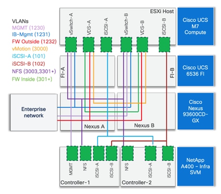
The ESXi host design highlights:
● Six vNICs in each ESXi host are configured as follows:
◦ Two redundant vNICs (vSwitch0-A and vSwitch0-B) carry management and infrastructure NFS traffic. Jumbo MTU (9000) is enabled on these vNICs for NFS traffic however management interfaces utilize MTU value to 1500.
◦ Two redundant vNICs (vDS0-A and vDS0-B) are used by the first VMware vSphere Distributed switch (vDS) and carry VMware vMotion traffic and all the tenant application data traffic. Jumbo MTU (9000) is enabled on these interfaces for vMotion and storage traffic however application port-groups typically use MTU value of 1500.
◦ Two vNICs are used by the iSCSI-A and iSCSI-B vDS. Infrastructure iSCSI VLANs are set as native VLANs on the corresponding vNICs. Jumbo MTU (9000) is enabled on these vNICs.
● Stateless boot from SAN using iSCSI is configured for the host and boot LUNs are configured on NetApp A400 Infrastructure tenant SVM.
● VMware vSphere ESXi is installed using the boot LUN on each host interactively using Cisco custom ISO.
● A DNS entry is created for the ESXi host.
● Management IP address is assigned to the host and host and domain name is configured.
● SSH access is enabled on the host.
● vSwitch0 (default virtual switch) MTU is set to 9000.
● NTP server IP is configured on the host.
Note: An NFS based volume is configured inside the infrastructure tenant SVM on NetApp A400 and each ESXi host mounts the NFS datastores from NetApp AFF A400 over the NFS VLAN. This datastore hosts all the tenant VMs.
The Cisco UCS X9508 Chassis is equipped with the Cisco UCS 9108-100G intelligent fabric modules (IFMs). The Cisco UCS X9508 Chassis connects to each Cisco UCS 6536 FI using two or more 100GE ports, as shown in Figure 26. If you require additional bandwidth, all eight ports on the IFMs can be connected to each FI. Each UCS C220 M7 rack server is equipped with Cisco 5th generation 25G or 100G VIC. Figure 26 illustrates how the Cisco UCS C220 M7 servers equipped with 25G VIC connects to each UCS 6536 FI using two 25GE ports.
In this validated design, the Cisco UCS X210c M7 compute nodes contain fifth-generation Cisco UCS 15231 virtual interface card (VIC) adapters and the Cisco UCS C220 M7 servers contain fifth-generation Cisco UCS 15428 VIC adapters.
Note: A 100G to 4 x 25G breakout cables is needed on the 6536 FI to support 25G connectivity.
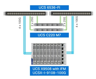
Cisco Nexus Ethernet Connectivity
The Cisco Nexus 93600CD-GX configuration covers the core networking requirements for Layer 2 and Layer 3 communication. Some of the key NX-OS features implemented within the design are:
● Feature interface-vans – Allows for VLAN IP interfaces to be configured within the switch as gateways.
● Feature HSRP – Allows for Hot Standby Routing Protocol configuration for high availability.
● Feature LACP – Allows for the utilization of Link Aggregation Control Protocol (802.3ad) by the port channels configured on the switch.
● Feature VPC – Virtual Port-Channel (vPC) presents the two Nexus switches as a single “logical” port channel to the connecting upstream or downstream device.
● Feature LLDP - Link Layer Discovery Protocol (LLDP), a vendor-neutral device discovery protocol, allows the discovery of both Cisco devices and devices from other sources.
● Feature NX-API – NX-API improves the accessibility of CLI by making it available outside of the switch by using HTTP/HTTPS. This feature helps with configuring the Cisco Nexus switch remotely using the automation framework.
● Feature UDLD – Enables unidirectional link detection for various interfaces.
● Feature NetFlow – Enables NetFlow configuration and setup export to Cisco Secure Network Analytics.
The two Nexus switches are connected to each other using two 400G ports. These ports are configured as a VPC peer-link port-channel.
Cisco UCS Fabric Interconnect 6536 Ethernet Connectivity
Cisco UCS 6536 FIs are connected to Cisco Nexus 93600CD-GX switches using 100GE connections configured as virtual port channels. Both FIs are connected to both Cisco Nexus switches using a single 100G connection however, additional links can easily be added to the port channel to increase the network bandwidth as required. Figure 27 illustrates the physical connectivity details.
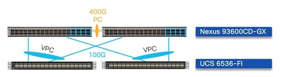
NetApp AFF A400 Ethernet Connectivity
NetApp AFF A400 controllers are connected to Cisco Nexus 93600CD-GX switches using 100GE connections configured as virtual port channels. The storage controllers are deployed in a switchless cluster configuration and are connected to each other using the 100GE ports e3a and e3b. Figure 28 illustrates the physical connectivity details.
Note: In Figure 28, the two storage controllers in the high-availability pair are drawn separately for clarity. Physically, the two controllers exist within a single chassis.

Cisco Intersight Managed Mode standardizes policy and operation management for Cisco UCS hardware used in this CVD. The Cisco UCS X210c compute nodes and Cisco UCS C220 M7 rack servers are configured using a server profile template in Cisco Intersight. The single server profile template allows compute admins to derive all the server characteristics from various associated policies and templates and deploy configurations uniformly on both rack servers and X-Series compute nodes. Some of the design highlights of the Cisco UCS configuration using Intersight Managed Mode are explained below.
You can choose to deploy two different service profile templates, one for Cisco UCS X-Series compute nodes and another for Cisco UCS C-Series rack servers for additional granularity and control. For example, if you want to enable certain features like Intel SGX only on a Cisco UCS C-series server because of compatibility requirements, a separate server profile template is a good way to achieve this.
Set up Cisco UCS Fabric Interconnect for Cisco Intersight Managed Mode
During the initial setup of the FIs, the Intersight Managed Mode (IMM) must be selected. You can switch the management mode for the fabric interconnects between Cisco Intersight and Cisco UCS Manager at any time, however this is a disruptive process.
Claim a Cisco UCS Fabric Interconnect in the Cisco Intersight Platform
After setting up the Cisco UCS fabric interconnect for Cisco Intersight Managed Mode, FIs must be claimed into a new or an existing Cisco Intersight account. When a Cisco UCS fabric interconnect is successfully added to the Cisco Intersight platform (Figure 29), all future configuration steps are completed in the Cisco Intersight web based graphical user interface (GUI).
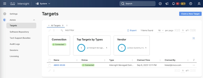
Cisco UCS Chassis Profile
The chassis profile in a FlexPod is used to set the power and thermal policies for the chassis. By default, Cisco UCSX power supplies are configured in GRID mode, but the power policy can be utilized to set the power supplies in non-redundant or N+1/N+2 redundant modes. The default thermal policy configures the chassis fans in the Balanced mode. Optional settings for the thermal policy are Low Power, High Power, Maximum Power, and Acoustic. In this CVD, the Cisco UCS Chassis profile is being configured with the default power and thermal policies to give you a starting point for optimizing chassis power usage.
The chassis-related policies can be attached to the profile either at the time of creation or later.
Cisco UCS Domain Profile
A Cisco UCS domain profile configures a fabric interconnect pair through reusable policies, allows configuration of the ports and port channels, and configures the VLANs (and VSANs) to be used in the network. It defines the characteristics of and configures the ports on the fabric interconnects. One Cisco UCS domain profile can be assigned to one fabric interconnect domain. Some of the key characteristics of the Cisco UCS domain profile for setting up FlexPod infrastructure used in this design are:
● A single domain profile is created for the pair of Cisco UCS fabric interconnects.
● Unique port policies are defined for the two fabric interconnects. The port policy (Figure 30) allows user to:
◦ Setup unified port mode to ethernet or FC.
◦ Setting up port type (server, uplink port channel, and so on).
◦ Setup ethernet and/or FC port channels.
◦ Enable breakout ports.
● All the VLANs are defined in the VLAN configuration policy. This VLAN configuration policy (Figure 30) is common to the fabric interconnect pair because both fabric interconnects are configured for the same set of VLANs.
● The Network Time Protocol (NTP), network connectivity, Link Control (UDLD), and system Quality-of-Service (QoS) policies are common to the fabric interconnect pair.
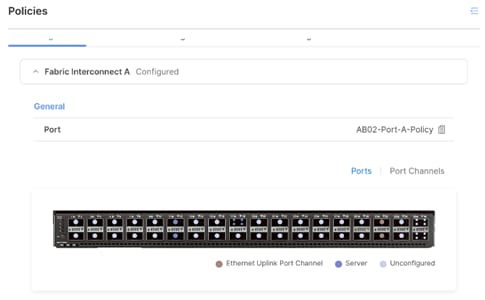
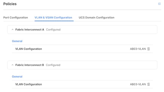
After the Cisco UCS domain profile has been successfully created and deployed, the policies including the port policies are pushed to the Cisco UCS fabric interconnects. Cisco UCS X9508 Chassis including Cisco UCS X210c M7 compute nodes and Cisco UCS C220 M7 rack servers are automatically discovered when the ports are successfully configured using the domain profile.
Server Profile Template
A server profile template enables resource management by simplifying policy alignment and server configuration. A server profile template is created using the server profile template wizard. Figure 32 shows various policies that should be defined for creating a server profile template.
Some of the characteristics of the server profile template are:
● BIOS policy is created to specify various server parameters in accordance with FlexPod best practices and Cisco UCS Performance Tuning Guides.
● Boot order policy defines virtual media (KVM mapped DVD) and all iSCSI SAN paths for NetApp iSCSI logical interfaces (LIFs).
● IMC access policy defines the management IP address pool for KVM access.
● Local user policy is used to enable KVM-based user access.
● LAN connectivity policy is used to:
◦ Create six virtual network interface cards (vNICs); two for management /NFS vSphere standard switch, two for vMotion and all the tenant traffic including tenant VLANs, and one each for two iSCSI virtual switches (A and B path).
◦ Various policies and pools including MAC pools and IP pools for iSCSI vNICs are defined as part of the LAN connectivity policy.
◦ Appropriate VLANs are enabled on each of the vNIC in the LAN connectivity policy as covered in logical design.
Figure 32 shows various policies associated with a server profile template:
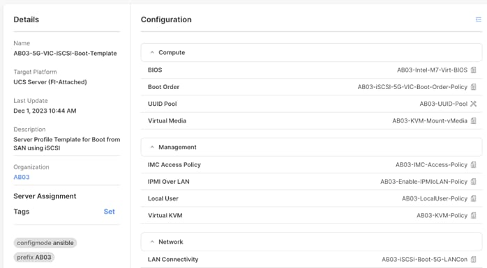
Derive and Deploy Server Profiles from the Cisco Intersight Server Profile Template
The Cisco Intersight server profile allows server configurations to be deployed directly on the compute nodes based on polices defined in the server profile template. After the server profile templates have been successfully created, server profiles can be derived from the template and associated with the Cisco UCS Compute Nodes. Figure 33 shows four server profiles, associated with two Cisco UCS X210c M7 and two Cisco UCS C220 M7 servers, derived from a single server profile template.
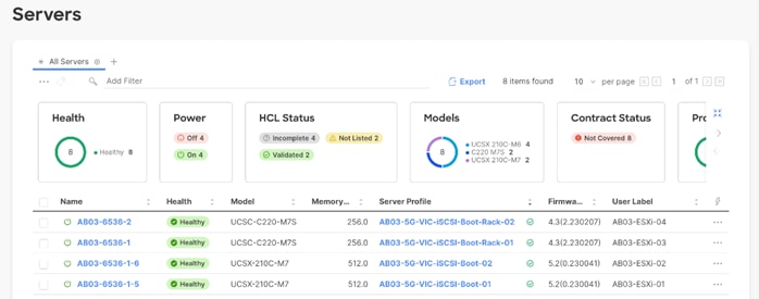
Other Policy and Profile Details
For detailed information about various Cisco UCS deployment options, see the FlexPod Datacenter with End-to-End 100G, Cisco Intersight Managed Mode, using Infrastructure as Code (IaC), VMware 7U3, and NetApp ONTAP 9.11 Deployment Guide. The deployment guide accompanying this design guide will also explain deployment details.
Storage Configuration
NetApp AFF A400 – Infrastructure Tenant Storage Virtual Machine (SVM) Design
To provide the necessary data segregation and management, a dedicated SVM is created for hosting the FlexPod infrastructure. The SVM contains the following volumes and logical interfaces (LIFs):
● Volumes
◦ ESXi boot LUNs used to enable ESXi host boot from SAN functionality.
◦ NFS datastore that acts as primary storage for the all the tenant VMs.
◦ NFS based VM and ESXi host swap file datastore.
◦ NFS based datastore used by the vSphere environment to host vSphere Cluster Services (vCLS) VMs.
● Logical interfaces (LIFs):
◦ SVM management interface in the IB-Mgmt (10.123.1.0/24; VLAN 1231) network.
◦ NFS LIFs to mount NFS datastores in the vSphere environment.
◦ iSCSI LIFs for supporting iSCSI SAN traffic.
Figure 34 shows the details of volumes, VLANs, and logical interfaces (LIFs).
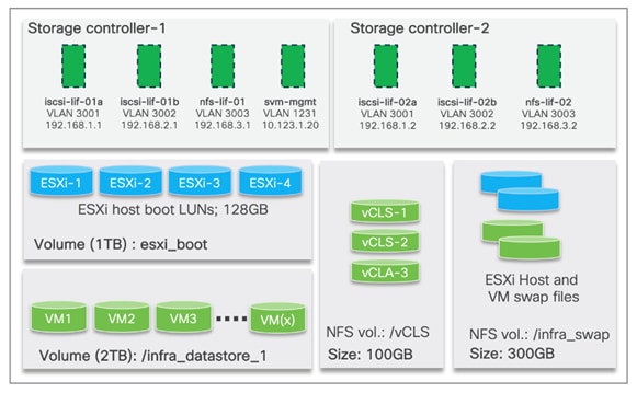
NetApp ONTAP is very flexible and provides a lot of storage configuration options. The infrastructure storage design discussed in the design is well suited for many enterprise customers but is not the only option for tenant storage configuration. By utilizing NetApp Storage Virtual Machines (SVMs) and IPspaces, instead of a common NFS datastore to host all the VMs, FlexPod also supports separate tenant NFS datastores, hosted in unique SVMs, for VM deployment. Similarly, FlexPod supports configuration of separate iSCSI (or FC) boot LUNs in tenant SVMs for booting tenant dedicated ESXi or bare metal servers. Both these options are sully supported but not validated as part of this design guide.
Segmentation and Control
Segmentation plays a crucial role in the Zero Trust security framework. Creating isolated zones within an infrastructure contain potential breaches and prevent attackers from moving laterally therefore limiting the scope of potential damage caused by a security breach. Even if an attacker gains access to one segment, they will have a much harder time reaching critical data or systems in other segments. Segmentation allows you to implement least privilege access control. This means users and devices only have access to the specific resources they need within their designated segment, minimizing the risk of unauthorized access to sensitive data.
Multi-tenants Infrastructure
In a multi-tenant infrastructure, multiple independent entities, such as users, customers, or organizations, share FlexPod resources while maintaining a level of isolation and separation. A secure multi-tenant environment guarantees the isolation and security of customer traffic and data. Zero Trust framework for FlexPod utilizes following three main technologies to provide a secure multi-tenant environment:
Virtual Routing and Forwarding Instances
Virtual Routing and Forwarding (VRF) create separate routing tables and forwarding instances, effectively dividing network into virtual layers. This isolates traffic between different segments, preventing unauthorized access and improves security. If you need the ability to support overlapping addresses in a multi-tenant environment, VRFs allows you to use the same IP address space in multiple segments without conflicts. VRFs are configured on the Cisco Nexus devices.
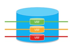
VLANs
Virtual Local Area Networks (VLANs) provide logical segmentation of a network, grouping devices together based on their functional roles, departments, or any other criteria. One of the major advantages of using VLANs is the ability to isolate and segregate network traffic.
● VLANs allows you to isolate traffic between different segments and contain the impact of security breaches or malicious activities, limiting the scope of potential attacks.
● By placing devices with similar security requirements in the same VLAN, administrators can implement access control and security policies at the VLAN level.
● VLANs provide a level of resource isolation between different parts of the network. For example, critical servers or sensitive systems can be placed in a separate VLAN with restricted access, reducing the likelihood of unauthorized access or attacks against those resources.
● Compromising one VLAN does not automatically grant access to devices in other VLANs, limiting lateral movement within the network.
VLANs are configured on Cisco Nexus, Cisco UCS, NetApp controllers, and VMware vSphere hypervisor environment. Depending on your deployment requirements, VLANs can also be configured on the Cisco Firewall Threat Defense virtual appliances.
Next Generation Firewalls
Cisco Secure Firewall Threat Defense (FTD) combines Cisco’s network firewall with Intrusion Prevention (IPS), URL filtering, and Advanced Malware protection (AMP) capabilities.
In this design, the Cisco Secure Firewall Threat Defense virtual (FTDv) appliance is utilized to secure the tenant network perimeter from all sorts of threats from users trying to access the resources hosted in the tenant segments. This design enables security controls like filtering, intrusion prevention and malware detection at the edge of the tenant infrastructure.
Refer to FTD compatibility matrix at: https://www.cisco.com/c/en/us/td/docs/security/secure-firewall/compatibility/threat-defense-compatibility.html#id_37873 for deployment details. The 7.2.5 version of FTDv is supported on vSphere 6.5, 6.7 and 7.0. In this deployment, vSphere 7.0U3 was used on FlexPod infrastructure.
Refer to: https://www.cisco.com/c/en/us/products/collateral/security/firepower-ngfw-virtual/threat-defense-virtual-ngfwv-ds.html#Productperformanceguidelines for obtaining the correct performance license for FTDv. In this deployment, FTDv20 license was used on the FTDv. This license assigns 4 vCPUs to the VM and support 3Gbps throughput. You can select a higher license to support FW+IPS+AVC throughput up to 15.5 Gbps.
FTDv appliances are managed using Firewall Management Center (FMC). The management interface of every FTDv is configured in IB-Mgmt (VLAN 1231) network and assigned a static IP address. FMC is also deployed in the same IB-Mgmt network and communicates directly with each of the FTDv. For firewall features are defined as policies and deployed to every FTDv appliance:
● Common base access control policy that blocks all the traffic from outside (unprotected) to inside (protected) interfaces.
● Common NAT policy that allows all the inside hosts to use outside interface’s IP address to communicate to the outside world.
● Tenant specific access control policies allowing application traffic from outside to inside interfaces.
● Tenant specific static NAT mappings for application web (and similar) services.
● DHCP is enabled on FTDv inside interface for VMs (if needed).
● Cisco recommended Intrusion prevention rules: https://www.cisco.com/c/en/us/td/docs/security/secure-firewall/management-center/device-config/720/management-center-device-config-72/intrusion-tailoring.html.
● Network Malware Protection and file policies: https://www.cisco.com/c/en/us/td/docs/security/secure-firewall/management-center/device-config/720/management-center-device-config-72/network-malware-protection.html.
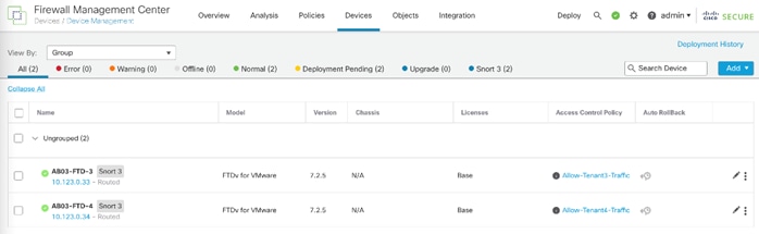
NetApp Storage Virtual Machine
NetApp Storage Virtual Machine (SVM) offers a flexible way to manage and secure data in a multi-tenant environment. SVMs provide isolation, security, resource allocation, and simplified management within the environment. Each SVM acts as a virtualized server with its own dedicated file system, LUNs, and security policies. This ensures complete isolation and prevents data leakage or unauthorized access between different SVMs. You can define and allocate specific resources like storage capacity, IOPS, and bandwidth to each SVM.
In this deployment, an infrastructure SVM is created to host the infrastructure services such as boot LUNs and NFS datastores to host the tenant VMs. All the remaining tenants are assigned dedicated SVMs to store their data and maintain isolation.
NetApp IPspace
IPspace in NetApp ONTAP offers a versatile tool for enhancing security, simplifying network management, and enabling flexible data access in a multi-tenant or multi-network environment. Each IPspace functions as a separate network, allowing you to define and enforce granular access control policies for different tenants. This ensures only authorized users can access specific storage resources within each IPspace. IPspaces simplify network management by logically separating different network segments within a single physical storage system and reduce the complexity of managing routing and firewall rules.
In this deployment, each SVM is assigned to a separate IPspace to maintain IP separation.
Tenant Design
This multi-tenant network design provides a secure, scalable, and flexible foundation for hosting multiple tenants with isolation. Figure 37 illustrates how the tenants are layered on top of an existing FlexPod infrastructure.
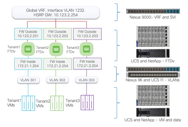
In this deployment model:
● Cisco Nexus 93600CD-GX acts as the primary gateway, offering each tenant an entry point into their respective resources.
● A Secure Firepower Threat Defense virtual (FTDv) firewall is deployed for each tenant. Deploying separate instances of firewall provide granular control and management separation.
● FTDv appliances are managed using Secure Firewall Management Center (FMC). You can choose to manage the firewalls using device manager, but FMC standardizes and simplifies firewall policy management.
● Appropriately sized FTDv is deployed as a VM in Cisco UCS and connected to port-group for outside (1232) and Inside VLANs (301+)
● All FTDv appliances use the same outside subnet and require a single gateway on Nexus 93600CD-GX. For added granularity, you can choose to use separate VLANs and subnets for the firewall outside interfaces.
● Each FTDv verifies incoming traffic flows such that it:
◦ Checks for application Network Address Translation (NAT) policies.
◦ Verifies access control policies.
◦ Applies other defined security policies such as URL filtering or IPS.
◦ Directs tenant traffic to protected networks using inside interfaces tied to separate VLANs.
● The protected traffic VLANs are defined on Nexus, UCS FI and VMware distributed switch. These inside VLANs play a pivotal role in segregating tenant traffic all the way to the Virtual Machines (VM). This design ensures that each tenant's traffic remains separate and secure within its own VLAN.
● The return traffic goes through similar checks on the firewalls and is forwarded back to outside interfaces of the firewalls.
Data Confidentiality
Zero Trust framework for FlexPod maintains tenant confidentiality and data security using stringent measures to ensure data integrity and security. Tenant data is kept secure by employing:
● Data isolation: this is achieved using Storage Virtual Machines (SVMs) and IPspaces. SVMs provide a secure, isolated environment for each tenant's data. By encapsulating a tenant's data within its own SVM, the design ensures that the data is isolated from other tenants and protected from unauthorized access. Similarly, IPspaces are used to create isolated network spaces, effectively segregating tenant network traffic and further enhancing data security.
● Secure operational environment: the FlexPod framework can (optionally) leverage Intel's confidential computing features. These include Trusted Memory Execution (TME) and Software Guard Extensions (SGX). TME provides a hardware-based mechanism to protect data in use, ensuring that it remains confidential and tamper-proof. Meanwhile, SGX allows applications to execute code and process data within their own private areas of memory, further enhancing data confidentiality and security.
In Zero Trust framework for FlexPod:
● Tenants VMs are installed on the Infrastructure NFS data volume. For additional isolation, you can choose to create NFS volumes within tenant SVM and mount the NFS file share in the VMware vSphere environment to host tenant VMs on their own volume.
● Tenant application data is provisioned using NFS volumes in a tenant specific SVM. You can also enable iSCSI-based LUNs in these SVMs and provide tenant VMs access to both NFS shares and iSCSI LUNs.
● An isolated VLAN provides tenant VMs direct network access to their tenant specific NFS shares.
● IPspaces, dedicated VLANs, non-routed subnets, and stringent export policies limit the data access.
● Tenant SVM management is controlled by using firewall rules and can be completely isolated from outside world.
Figure 38 shows how the tenants, IPspaces and Logical Interfaces (LIFs) are defined on the two storage controllers. Management LIF is configured to move between the two controllers as needed. This design allows VMs to access their NFS volumes directly therefore providing fast low-latency access.
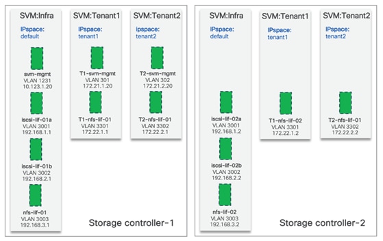
Secure Execution Environment – Intel Confidential Computing (optional)
Cisco UCS M7 servers allows you to enable Intel Total Memory Encryption (TME) and Intel Software Guard Extensions (SGX) using BIOS policies.
Intel TME encrypts a computer’s entire memory with a single transient key. All memory data passing to and from the CPU is encrypted. This includes memory data such as customer credentials, encryption keys, and other IP or personal information. Intel TME has a relatively small performance impact, but all the hypervisor and bare metal OS features are supported without any special considerations.
VMware vSphere allows the configuration of Virtual Intel Software Guard Extensions (vSGX) for enhanced security of virtual machine workloads. vSGX extends this technology to virtual machines if the underlying hardware supports SGX. To enable vSGX, an SGX-enabled CPU and the corresponding BIOS setting on the ESXi host and can be enabled for a virtual machine using the vSphere Client. The following features are not supported in a virtual machine when vSGX is enabled:
● vMotion/DRS migration.
● VM suspend and resume.
● VM snapshots - VM snapshots are supported if virtual machine's memory is excluded from snapshot.
● Fault tolerance.
For more information, go to: https://docs.vmware.com/en/VMware-vSphere/7.0/com.vmware.vsphere.security.doc/GUID-C81950B5-CD0A-40CA-9945-1104A92F4455.html
Visibility and Continuous Monitoring
Network visibility and continuous monitoring is a fundamental aspect of any Zero Trust framework. It involves the ability to monitor and manage the entire network in real-time, providing insights into traffic patterns, performance metrics, and potential security threats. Effective network visibility can enhance troubleshooting, improve performance, and strengthen security defenses.
Zero Trust framework for FlexPod includes visibility at all layers of the infrastructure including switches, firewalls, hypervisor, storage, and application virtual machines. In addition to the individual element managers, the solution incorporated Cisco Secure Network Analytics (Stealthwatch) to combine comprehensive statistics gathered using NetFlow records with machine learning algorithms to identify potential threats and provide comprehensive visibility into network activities.
Element Managers
This section explains the various network and traffic visibility features offered by individual element managers.
VMware vCenter
VMware vCenter provides comprehensive visibility into the virtual network traffic generated by ESXi hosts and the VMs. This information is crucial for troubleshooting network issues and optimizing performance. Additionally, vCenter provides information about CPU and memory usage of all the virtualized infrastructure to help identify performance issues.
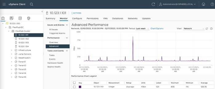
NetApp ONTAP System Manager
NetApp ONTAP System Manager offers granular visibility into storage network traffic. It provides insights into performance metrics, capacity usage, and data flow. This visibility is essential for optimizing storage performance, planning capacity, and identifying potential issues.
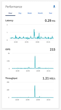
Cisco Intersight
Intersight Metrics Explorer allows you to aggregate and visualize various UCS metrics that are collected for Fabric Interconnects, Chassis, and Servers that are managed as Intersight Managed Mode (IMM) Domains in Cisco Intersight. You can use the Metrics Explorer queries to monitor your devices, optimize performance, identify bottlenecks, and proactively address any potential issues. For more information, go to: https://intersight.com/help/saas/features/monitoring/monitoring_metrics_explorer
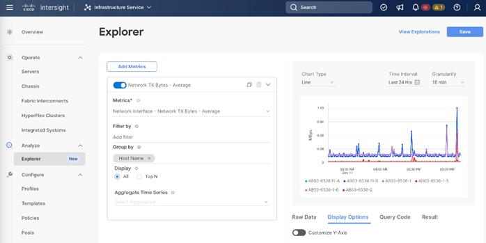
Firewall Management Center
Firewalls play a crucial role in protecting the network perimeter. Beyond blocking unwanted traffic, modern firewalls also provide valuable network visibility. They can analyze traffic patterns, detect anomalies, and even provide insights into application usage. This level of visibility is key to identifying potential security threats and maintaining network performance. Cisco Secure FMC aggregated and provides visibility across all the firewall network and application traffic that traverses the FTDv appliance deployed in the tenant environment as shown in Figure 42.
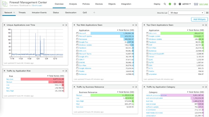
Cisco Secure Network Analytics
Cisco Secure Network Analytics performs extensive monitoring of network traffic using data collected from NetFlow devices across the network. Secure Analytics performs heuristic inspection of encrypted and unencrypted flows. It uses advanced analytics to detect anomalous patterns that could indicate a security threat.
Cisco Network Analytics on-prem virtual appliances can be deployed in one of the following two configurations:
● Cisco Network Analytics without Data Store
● Cisco Network Analytics with Data Store
Secure Network Analytics without Data Store
In a Secure Network Analytics deployment without a Data Store, one or more Flow Collectors ingests and deduplicates data, performs analysis, and reports data and results directly to the Manager. To resolve user-submitted queries, including graphs and charts, the Manager queries all the managed Flow Collectors. Each Flow Collector returns matching results to the Manager. The Manager collates the information from the different result sets, then generates a graph or chart displaying the results. In this deployment, each Flow Collector stores data on a local database.
Secure Network Analytics with Data Store
In a Secure Network Analytics deployment with a Data Store, the Data Store cluster sits between the Manager and Flow Collectors. One or more Flow Collectors ingests and deduplicates flows, performs analysis, and reports data and results directly to the Data Store, distributing it roughly equally to all the Data Nodes. The Data Store facilitates data storage, keeps all the traffic in that centralized location as opposed to spread across multiple Flow Collectors, and it offers greater storage capacity than multiple Flow Collectors.
For details about installation requirement, sizing information, and different deployment models, go to: https://www.cisco.com/c/dam/en/us/td/docs/security/stealthwatch/system_installation_configuration/7_4_2_VE_Appliance_Installation_Guide_DV_1_7.pdf.
In Zero Trust framework for FlexPod design, Secure Network Analytics without Data Store deployment is utilized. Secure Network Analytics is deployed as virtual appliances on the VMware infrastructure as follows:
● Secure Network Analytics is deployed as two VMs, a Flow Collector VM, and a Management Center VM.
● Both Management Center and Flow Collector VMs are deployed in the IB-Mgmt (VLAN 1231) network and communicate with each other directly.
● Flow Collector is added to the Management Center.
● NetFlow is enabled on the following devices to provide full infrastructure visibility:
◦ Cisco Nexus 93600CD-GX VPCs capturing traffic in and out of UCS, NetApp controllers, management network, and enterprise connections.
◦ Cisco FTDv appliances.
◦ VMware ESXi hosts.
● NetFlow records are exported to the Flow Collector which receives, decodes, and stores flow data.
● Configurations and traffic analysis is performed via the Management Console including setting up user accounts, configuring Flow Collectors, and setting up alerts.
Once the Secure Network Analytics finishes identifying the entities, it baselines their behavior over a fixed period. As soon as the baselining is completed, any unexpected behavioral change of the entities will generate and alert. This helps maintain deep visibility into the infrastructure environment.
Dashboard
Secure Analytics Dashboard provides and overview of the infrastructure including alerts, alarms, and traffic breakdown. You can select the alarms and gather all the relevant details such as why an alarm was generated, which host(s) was involved and how the traffic behaved. This information can help administrators quickly identify, troubleshoot, and fix common infrastructure problems.
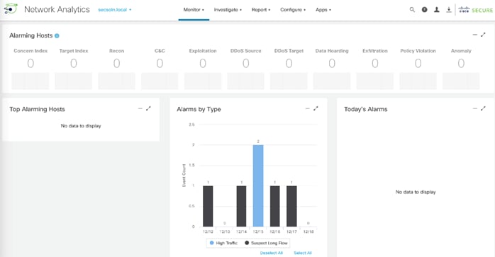
Secure Network Analytics dashboard also provides you with granular tools to identify and track traffic flows over time as shown in Figure 44.
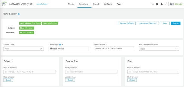
Threat Protection and Response
In the Zero Trust framework for FlexPod design, threat protection and response are provided by:
● Secure Workload SaaS solution which delivers important visibility and micro-segmentation within the tenant application environments.
● NetApp Autonomous Ransomware Protection (ARP) which provides data classification, protection, and recovery.
Secure Workload SaaS (previously Cisco Tetration)
Cisco Secure Workload SaaS dashboard provides a comprehensive overview of the workload environment. This information is gathered by installing host agents on the workload VMs.
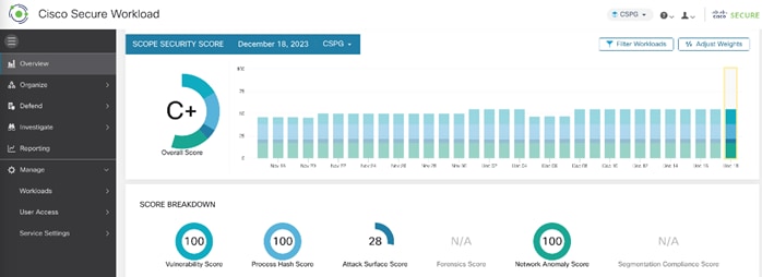
Cisco Secure Workload Setup
Setting up Cisco Secure Workload SaaS is straight forward and involves following main steps:
● Sign up for the Cisco Secure Workload SaaS: Subscribe to the Cisco Secure Workload SaaS solution and use the unique URL to access the SaaS instance.
● Install Sensors: Cisco Secure Workload uses sensors to gather data from the workload VMs. You will need to install these sensors on the virtual machines and bare metal servers. The sensor installation process varies depending on the operating system and the environment. Refer to following compatibility matrix: https://www.cisco.com/c/m/en_us/products/security/secure-workload-compatibility-matrix.html.
● Configure Sensors: Use the recommended agent installation using script as shown in Figure 46. Using this method, agents automatically connect to the Secure Workload SaaS instance.
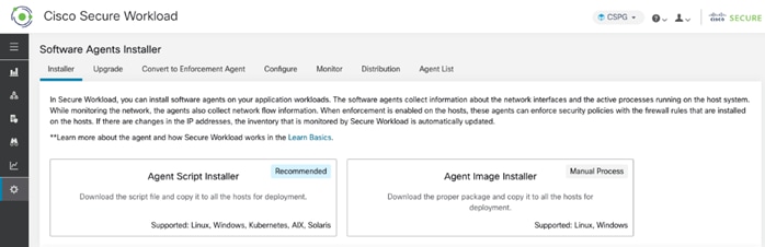
● Set up and enforce policies: Once the sensors are installed and communicating with the SaaS instance, define policies. Policies determine how workloads can communicate with each other and what actions to take when policy violations occur.
● Monitor: Cisco Secure Workload provides a wealth of information, including application dependencies, process information, software vulnerabilities, and policy compliance.
Policy and Enforcement
Cisco Secure Workload provides deep visibility into applications running in the data center, mapping out dependencies and communication patterns. This information is crucial for creating effective micro-segmentation policies. It helps to identify security incidents within your infrastructure, such as lateral movement, policy violations, or indicators of compromise. It also aids in enforcing a zero-trust model across your infrastructure. Cisco Secure Workload can also identify software vulnerabilities in the environment and help expedite software upgrades and patch deployment to mitigate risk.
Cisco Secure Workload provides in-depth information about the workload VMs including:
● Processes running on the VMs.
● OS vulnerabilities.
● Network, CPU, and memory statistics.
● Packages installed.
● Interfaces and IP addresses.
● Several other parameters
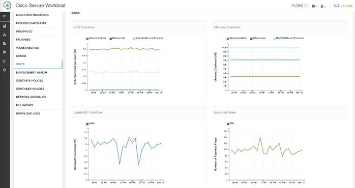
Micro Segmentation
One of the key advantages of VM installed agent is Cisco Secure Workload’s ability to control the host-based firewall and lock the host down when the host is compromised. This allows implementation of micro-segmentation in the FlexPod environment. You can define the policies manually or by using the Cisco Secure Workload's application dependency mapping feature to get visibility into your applications' communication patterns. Once the policies are in place, monitor their impact and effectiveness using Cisco Secure Workload's monitoring features and adjust the policies as needed to maintain security and efficiency.
NetApp Autonomous Ransomware Protection
NetApp Autonomous Ransomware Protection (ARP) is a built-in feature of the ONTAP operating system that helps protect NAS (Network Attached Storage) data from ransomware attacks. It uses machine learning and anomaly detection to identify suspicious activity and automatically take action to prevent data loss.
Deployment considerations:
Some of the key deployment considerations for NetApp APR are:
● ARP is currently available for ONTAP 9.10 and later versions.
● It requires a valid NetApp Support contract with active subscriptions for Data Protection and Security.
● You need to configure ARP for each volume you want to protect.
● ARP offers different modes (Learning, Active, Disabled) with varying levels of protection and automation.
For more information, go to: https://docs.netapp.com/us-en/ontap/anti-ransomware/#licenses-and-enablement.
NetApp ARP modes
ARP has two modes:
● Learning (or "dry run" mode)
● Active (or "enabled" mode)
When ARP is enabled, it runs in learning mode. In learning mode, the ONTAP system develops an alert profile based on entropy, file extension types, and file IOPS. After running ARP in learning mode for enough time to assess workload characteristics, you can switch to active mode and start protecting your data. Once ARP has switched to active mode, ONTAP will create ARP snapshots to protect the data if a threat is detected.
Note: It's recommended that you leave ARP in learning mode for a minimum of 30 days. Beginning with ONTAP 9.13.1, ARP automatically determines the optimal learning period interval and automates the switch, which may occur before 30 days. For more information, go to: https://docs.netapp.com/us-en/ontap/anti-ransomware/#learning-and-active-modes.
NetApp ONTAP includes features like FPolicy, Snapshot copies, SnapLock, and Active IQ Digital Advisor to help protect from ransomware. ARP takes it a step further and utilizes machine-learning and simplifies the detection and recovery from a ransomware attack. ARP can detect the spread of most ransomware attacks after only a small number of files are encrypted, acts automatically to protect data, and alerts you about a suspected attack. When an attack is suspected, the system takes a volume Snapshot copy at that point in time and locks that copy. If the attack is confirmed later, the volume can be restored to this proactively taken snapshot to minimize the data loss.
Design Considerations
This chapter contains the following:
● Management Design Considerations
Some of the key design considerations for the Zero Trust Framework for FlexPod are explained in this section.
Management Design Considerations
Out-of-band Management Network
The management interface of every physical device in FlexPod is connected to a dedicated out-of-band management switch which can be part of the existing management infrastructure in your environment. The out-of-band management network provides management access to all the devices in the FlexPod environment for initial and on-going configuration changes. The routing and switching configuration for this network is independent of FlexPod deployment and therefore changes in FlexPod configurations do not impact management access to the devices.
In-band Management Network
The in-band management VLAN configuration is part of FlexPod design. The in-band VLAN is configured on Nexus switches and Cisco UCS within the FlexPod solution to provide management connectivity for vCenter, ESXi and other management components. The changes to FlexPod configuration can impact the in-band management network and misconfigurations can cause loss of access to the management components hosted by FlexPod. In addition to the core management components, Cisco Secure FTD, Cisco Secure Network analytics and NetApp components all are managed using in-band management network.
In FlexPod infrastructure, when utilizing Cisco UCS Server technology with shared storage, it is recommended to configure boot from SAN and store the boot partitions on remote storage. This enables architects and administrators to take full advantage of the stateless nature of Cisco UCS C-Series and X-Series Server Profiles for hardware flexibility across the server hardware and overall portability of server identity. Boot from SAN also removes the need to populate local server storage thereby reducing cost and administrative overhead.
An MTU of 9216 is configured at all network levels to allow jumbo frames as needed by the guest OS and application layer. The MTU value of 9000 is used on all the vSphere Distributed Switches (VDS) in the VMware environment.
FlexPod utilizes dedicated storage access VLANs for iSCSI and NFS traffic that are isolated from the rest of the network. Isolated VLANs provide a robust security mechanism to protect sensitive information because these VLANs have no direct access to the other network segments resulting in a reduced risk of unauthorized access or potential data breaches. This isolation not only keeps the storage traffic safe but also ensures that it remains segregated from other network traffic providing better control and quality of service (if implemented).
The multi-tenant design introduced in this deployment is very versatile and caters to a broad spectrum of use cases. Figure 48 illustrates one of the more straightforward tenant designs which despite its simplicity, covers a wide array of use cases that apply to many customers. This modular tenant design allows it to be easily adapted and implemented according to your requirements. Two additional common tenant designs that can be deployed are covered here. These designs were not validated in the lab as part of this CVD.
Single Firewall Tenant Design
In this design, a single firewall provides security for all the tenants and the security policies are defined within a single firewall. This deployment model is ideal for customers looking for a straightforward, easy-to-manage solution based on a single firewall and multiple DMZ interfaces. However, this design lacks the following design elements:
● Per-tenant granular policy control provided by separate firewalls is sometimes replaced by more complex policies defined on a single firewall.
● Overlapping address spaces for the tenants is not supported.
● Additional policies and considerations to keep the traffic separate between firewall segments must be implemented.
● Additional, sometimes complex, NAT and ACL rules are required to enable tenants to tenant communication.
● Interface and other resource limitations result in reduced number of supported tenants.
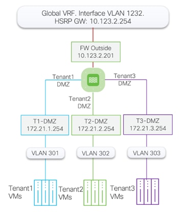
In this deployment model:
● Cisco Nexus 93600CD-GX acts as the primary gateway for the firewall.
● A single Secure Firepower Threat Defense virtual (FTDv) firewall is deployed for all the tenants.
● FTDv appliance can be managed using device manager however for future proofing, FMC is recommended.
● Appropriately sized FTDv is deployed as a VM in Cisco UCS and connected to port-group for outside (1232) and all the tenant DMZ VLANs (301+). Sub-interfaces on the firewalls can be utilized for scalability.
● The protected traffic VLANs are defined on Nexus, UCS FI and VMware distributed switch. These DMZ VLANs play a pivotal role in segregating tenant traffic all the way to the Virtual Machines (VM). This design ensures that each tenant's traffic remains separate and secure within its own VLAN.
Multiple Tenant Subnets
This design is suitable for the tenants that require multiple protected application subnets where VMs need to communicate to each other directly. This type of configuration is suitable for customers who require a more granular level of control over their application and network traffic. By utilizing tenant VRFs on the Cisco Nexus, the tenant traffic is routed on the Nexus switches. For example, as shown in Figure 49, if Tenant-1 Web servers in one subnet need to communicate to the Tenant-1 Application servers in another subnet, the traffic can be routed on the Cisco Nexus without the need to go through the firewall and consume firewall bandwidth and resources.
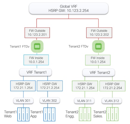
In this deployment model:
● Cisco Nexus 93600CD-GX acts as the primary gateway, offering each tenant an entry point into their respective resources.
● A Secure Firepower Threat Defense virtual (FTDv) firewall is deployed for each tenant.
● FTDv appliances are managed using Secure Firewall Management Center (FMC).
● Appropriately sized FTDv is deployed as a VM in Cisco UCS and connected to port-group for outside (1232) and Inside VLANs.
● All FTDv appliances use the same outside subnet and require a single gateway on Nexus 93600CD-GX. For added granularity, you can choose to use separate VLANs and subnets for the firewall outside interfaces.
● This design supports overlapping tenant IP addresses, but unique IP address ranges are preferred to obtain meaningful IP address related information in the monitoring tools.
● Traffic between the same-tenant VLANs is routed on Cisco Nexus switches and does not need to go through firewall.
Note: The two designs explained in this section are provided as a reference. You can easily modify these tenant designs or deploy a new design based on your individual requirements.
In addition to command line interface (CLI) and graphical user interface (GUI) configurations, explained in the deployment guide, all FlexPod components support configurations through automation frameworks such as Ansible and Terraform etc. The FlexPod solution validation team develops automation modules to configure Cisco Nexus, Cisco UCS, Cisco MDS, NetApp ONTAP, NetApp ONTAP Tools for VMware, Active IQ Unified Manager and VMware ESXi (initial configuration). This community-supported GitHub repository is meant to expedite your adoption of automation by providing you with sample configuration playbooks that can be easily developed or integrated into your existing automation frameworks. Another key benefit of the automation package is the reusability of the code and roles to help you execute repeatable tasks within your environment.
The Zero Trust framework for FlexPod Datacenter design incorporates various security products and components providing a robust framework that extends to all layers, including network, compute, hypervisor, and storage and includes implementation of tenant-based segmentation. This latest FlexPod design uses a hardened infrastructure that follows several security best practices including segmentation, authentication, and secure transport protocols for all communication. Cisco Secure Firepower Threat Defense devices are used to control both client-to-server and server-to-server traffic, ensuring secure communication across application tiers and tenants. Cisco Secure Workload is utilized for both OS and process visibility on workload VMs as well as for threat mitigation by employing micro segmentation. The solution enhances application and tenant visibility using NetFlow export from switches, firewalls, and the hypervisor to Cisco Secure Network Analytics which uses machine learning for anomaly detection. Confidential data is protected at runtime using technologies provided by Intel Confidential Compute and data-in-flight/rest isolation is achieved on NetApp using IP Spaces and Storage Virtual Machines. Data classification, protection, and recovery are provided using NetApp Autonomous Ransomware Protection to ensures the integrity and safety of data.
Haseeb Niazi, Principal Technical Marketing Engineer, Cisco Systems, Inc.
With more than two decades of experience at Cisco, Haseeb has built extensive expertise in Datacenter, Enterprise, and Service Provider Solutions and Technologies. As part of various solution teams and Advanced Services, he has guided numerous enterprise and service provider clients in the evaluation and deployment of a broad range of Cisco solutions. In his current role as a Principal Technical Marketing Engineer at the Cisco UCS business entity, Haseeb concentrates on multiple facets of various compute stacks, including networking, compute, virtualization, storage, and orchestration. Haseeb holds a master’s degree in computer engineering from the University of Southern California and is a Cisco Certified Internetwork Expert (CCIE 7848).
Jyh-shing Chen, Senior Technical Marketing Engineer, Hybrid Cloud Infra & OEM Solutions, NetApp Inc.
Jyh-shing Chen is a Senior Technical Marketing engineer at NetApp. His current focus is on FlexPod Converged Infrastructure solution enablement, validation, deployment and management simplification, and solution integration with Cisco Intersight. Jyh-shing joined NetApp in 2006 and had worked on storage interoperability and integration projects with Solaris and VMware vSphere operating systems, and qualifications of ONTAP MetroCluster solutions and Cloud Volumes data services. Before joining NetApp, Jyh-shing’s engineering experiences include software and firmware development on cardiology health imaging system, mass spectrometer system, Fibre Channel virtual tape library, and the research and development of microfluidic devices. Jyh-shing earned his BS and MS degrees from National Taiwan University, MBA degree from Meredith College, and PhD degree from MIT.
Acknowledgements
For their support and contribution to the design, validation, and creation of this Cisco Validated Design, the authors would like to thank:
● John George, Technical Marketing Engineer, Cisco Systems, Inc.
● Ryan Maclennan, Technical Marketing Engineer, Cisco Systems, Inc.
● Kamini Singh, Technical Marketing Engineer, NetApp Inc.
This appendix contains the following:
● Appendix A - References used in this guide
Appendix A – References used in this guide
Cisco Intersight: https://www.intersight.com
Cisco Intersight Managed Mode: https://www.cisco.com/c/en/us/td/docs/unified_computing/Intersight/b_Intersight_Managed_Mode_Configuration_Guide.html
Cisco Unified Computing System: http://www.cisco.com/en/US/products/ps10265/index.html
Cisco UCS 6536 Fabric Interconnects: https://www.cisco.com/c/en/us/products/collateral/servers-unified-computing/ucs6536-fabric-interconnect-ds.html
Cisco Nexus 9000 Series Switches: http://www.cisco.com/c/en/us/products/switches/nexus-9000-series-switches/index.html
Cisco MDS 9132T Switches: https://www.cisco.com/c/en/us/products/collateral/storage-networking/mds-9100-series-multilayer-fabric-switches/datasheet-c78-739613.html
NetApp ONTAP: https://docs.netapp.com/ontap-9/index.jsp
NetApp Active IQ Unified Manager: https://community.netapp.com/t5/Tech-ONTAP-Blogs/Introducing-NetApp-Active-IQ-Unified-Manager-9-11/ba-p/435519
NetApp ONTAP Storage Connector for Cisco Intersight: https://www.netapp.com/pdf.html?item=/media/25001-tr-4883.pdf
NetApp ONTAP tools for VMware vSphere: https://docs.netapp.com/us-en/ontap-tools-vmware-vsphere/index.html
NetApp SnapCenter: https://docs.netapp.com/us-en/snapcenter/index.html
VMware vCenter Server: http://www.vmware.com/products/vcenter-server/overview.html
VMware vSphere: https://www.vmware.com/products/vsphere
Cisco UCS Hardware Compatibility Matrix: https://ucshcltool.cloudapps.cisco.com/public/
VMware and Cisco Unified Computing System: http://www.vmware.com/resources/compatibility
NetApp Interoperability Matrix Tool: http://support.netapp.com/matrix/
For comments and suggestions about this guide and related guides, join the discussion on Cisco Community at https://cs.co/en-cvds.
CVD Program
ALL DESIGNS, SPECIFICATIONS, STATEMENTS, INFORMATION, AND RECOMMENDATIONS (COLLECTIVELY, "DESIGNS") IN THIS MANUAL ARE PRESENTED "AS IS," WITH ALL FAULTS. CISCO AND ITS SUPPLIERS DISCLAIM ALL WARRANTIES, INCLUDING, WITHOUT LIMITATION, THE WARRANTY OF MERCHANTABILITY, FITNESS FOR A PARTICULAR PURPOSE AND NONINFRINGEMENT OR ARISING FROM A COURSE OF DEALING, USAGE, OR TRADE PRACTICE. IN NO EVENT SHALL CISCO OR ITS SUPPLIERS BE LIABLE FOR ANY INDIRECT, SPECIAL, CONSEQUENTIAL, OR INCIDENTAL DAMAGES, INCLUDING, WITHOUT LIMITATION, LOST PROFITS OR LOSS OR DAMAGE TO DATA ARISING OUT OF THE USE OR INABILITY TO USE THE DESIGNS, EVEN IF CISCO OR ITS SUPPLIERS HAVE BEEN ADVISED OF THE POSSIBILITY OF SUCH DAMAGES.
THE DESIGNS ARE SUBJECT TO CHANGE WITHOUT NOTICE. USERS ARE SOLELY RESPONSIBLE FOR THEIR APPLICATION OF THE DESIGNS. THE DESIGNS DO NOT CONSTITUTE THE TECHNICAL OR OTHER PROFESSIONAL ADVICE OF CISCO, ITS SUPPLIERS OR PARTNERS. USERS SHOULD CONSULT THEIR OWN TECHNICAL ADVISORS BEFORE IMPLE-MENTING THE DESIGNS. RESULTS MAY VARY DEPENDING ON FACTORS NOT TESTED BY CISCO.
CCDE, CCENT, Cisco Eos, Cisco Lumin, Cisco Nexus, Cisco StadiumVision, Cisco TelePresence, Cisco WebEx, the Cisco logo, DCE, and Welcome to the Human Network are trademarks; Changing the Way We Work, Live, Play, and Learn and Cisco Store are service marks; and Access Registrar, Aironet, AsyncOS, Bringing the Meeting To You, Catalyst, CCDA, CCDP, CCIE, CCIP, CCNA, CCNP, CCSP, CCVP, Cisco, the Cisco Certified Internetwork Expert logo, Cisco IOS, Cisco Press, Cisco Systems, Cisco Systems Capital, the Cisco Systems logo, Cisco Unified Computing System (Cisco UCS), Cisco UCS B-Series Blade Servers, Cisco UCS C-Series Rack Servers, Cisco UCS S-Series Storage Servers, Cisco UCS X-Series, Cisco UCS Manager, Cisco UCS Management Software, Cisco Unified Fabric, Cisco Application Centric Infrastructure, Cisco Nexus 9000 Series, Cisco Nexus 7000 Series. Cisco Prime Data Center Network Manager, Cisco NX-OS Software, Cisco MDS Series, Cisco Unity, Collaboration Without Limitation, EtherFast, EtherSwitch, Event Center, Fast Step, Follow Me Browsing, FormShare, GigaDrive, HomeLink, Internet Quotient, IOS, iPhone, iQuick Study, LightStream, Linksys, MediaTone, MeetingPlace, MeetingPlace Chime Sound, MGX, Networkers, Networking Academy, Network Registrar, PCNow, PIX, PowerPanels, ProConnect, ScriptShare, SenderBase, SMARTnet, Spectrum Expert, StackWise, The Fastest Way to Increase Your Internet Quotient, TransPath, WebEx, and the WebEx logo are registered trade-marks of Cisco Systems, Inc. and/or its affiliates in the United States and certain other countries. (LDW_P2)
All other trademarks mentioned in this document or website are the property of their respective owners. The use of the word partner does not imply a partnership relationship between Cisco and any other company. (0809R)