NextGen Out-of-Band Data Center Management Network with EVPN VXLAN
Available Languages
Bias-Free Language
The documentation set for this product strives to use bias-free language. For the purposes of this documentation set, bias-free is defined as language that does not imply discrimination based on age, disability, gender, racial identity, ethnic identity, sexual orientation, socioeconomic status, and intersectionality. Exceptions may be present in the documentation due to language that is hardcoded in the user interfaces of the product software, language used based on RFP documentation, or language that is used by a referenced third-party product. Learn more about how Cisco is using Inclusive Language.
- US/Canada 800-553-2447
- Worldwide Support Phone Numbers
- All Tools
 Feedback
 Feedback
What will you learn?
Let’s walk through deploying an EVPN VXLAN based NextGen out-of-band (OOB) data center management network using Cisco Nexus 9000 Series Switches with Cisco Nexus Dashboard Fabric Controller to provide inherent security, deployment extensibility, operational flexibility, unified visibility, and functional segmentation or multitenancy.
These benefits translate directly to the following results.
● Reduced operational cost and risk
● Reduced capital expenditure
● Increased stability, operational control, and visibility
● Increased functional capability, platform consolidation, and longevity
Prerequisites
This document presumes that you have an understanding of fundamental network routing and switching design. You must be familiar with EVPN VXLAN secure multitenancy, site-internal underlay/overlay functionality, and DCI (specifically, vPC border gateway) concepts. It is suggested that you be familiar with Cisco Nexus Dashboard Fabric Controller for LAN, and Cisco Nexus 9000 Series switching platform.
Introduction
This design reference document details the technical and operational benefits, and deployment considerations for implementing a secure, flexible, NextGen OOB management network using Nexus 9000 Series Switches and Nexus Dashboard Fabric Controller.
An out-of-band network is a physically separate network that is used to decouple the control and management of the data center network infrastructure from production workload traffic. This differs from inband management where connectivity is accomplished using the same physical connections as production application workload traffic.
The OOB network provides IP-based reachability to common network infrastructure components such as routers, switches, and servers, as well as an ever-growing group of IP-aware IoT devices including heating ventilation, and air conditioning (HVAC) systems, and power distribution units (PDUs). Also, as the number of IoT devices and network-connected endpoints continues to grow, there is an increased focus on visibility, security, and segmentation that has not typically been an inherent requirement of OOB design until recently.
An OOB network differs from external console access in the following areas:
● It is continuously utilized.
● Endpoint connectivity is accomplished via an IP network.
● External reachability is typically routed through a shared data center network core.
External console access does not rely on IP reachability as management is accomplished using an async (serial) connection, and the leading practice is to provision a dedicated connection for external reachability, often via a separate internet circuit or cellular backup connection. External console access is only used if there is a network down emergency.
While external console access and inband management are both important design considerations, the focus of this paper is specific to out-of-band (OOB) network design.
Note: Cisco Cloud-Scale Nexus 9000 Series data center switches (-EX and later) are the only models that are referenced throughout this document. Older generation Nexus 9000 Series Switch models and other data center switch platforms such as the Nexus 5000 Series Switch lines are no longer sold and are into the hardware lifecycle EoL process timeline.
Traditional OOB Network Design
It is commonplace to design an OOB network using technologies that reduce the number of network elements that are required to be configured and managed. This decreases operational overhead by reducing the number of managed elements, or logical devices within the OOB network.
Minimizing the operational footprint of the OOB network is most often accomplished by using:
· Fabric Extenders (FEX), which are separate physical switches that logically operate as a remote line card to the upstream Cisco Nexus data center switch.
· Physical or virtual switch stacking technologies, which provide the ability to manage multiple physical Cisco Catalyst switches as a single logical element.
OOB platform and technology choice depends on both the physical cable plant within the data center, as well as cost and operational familiarity.
Common OOB network design practices using FEX
The following figure illustrates the design of a physically redundant topology with up to 16 FEXs homed to a single pair of upstream Nexus devices, allowing for a total of 18 physical switches to be managed as two logical devices.
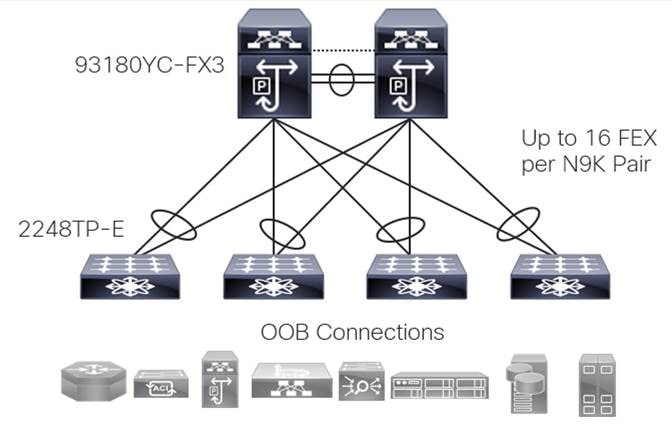
A FEX-based OOB design has often been the go-to solution of choice as it has proven to be:
● Scalable - A single pair of Nexus switches can host up to 16 N2K FEX giving us 18 physical boxes that are managed and operated as two logical devices
● Redundant - Upstream physical path diversity using vPC
● Low Cost - The FEX platform has a lower purchase cost than the upstream switches that govern them
● Operable – There is little to no learning curve associated with the operation of this design as the technology has been used in data centers for 10+ years
Limitations inherent to the FEX-based OOB design
There are design and functional limitations inherent with a FEX-based design that are becoming more apparent given advancements in platform hardware as well as an industry-wide evolution in leading practice design that moves away from spanning tree (STP), First Hop Redundancy Protocols (HSRP or VRRP), and heavy back-to-back vPC use.
Limitations of FEX-based OOB design include:
● Large Scale - OOB switch deployment often requires a high number of ToR switches – as such there is often a requirement for multiple Nexus 9000 Series switches + FEX pairs as we are limited to 16 total FEXs per Nexus 9000 Series switch pair – this introduces the need for another level of OOB hierarchy (3 physical tiers).
● Current and forward-looking functionality - FEX-based OOB management networks are isolated per physical site/DC location which does not adhere to forward looking design (cloud edge or distributed workload placement).
● Segmentation - Depending on a customer’s security policy, OOB network subnets may not be routable outside a given site which can limit management functionality.
● Visibility – While they do help to consolidate the logical footprint, FEXs provide no intelligence, limited functionality, and little to no visibility or operational metric data.
● Platform longevity - The industry has shifted to EVPN VXLAN as the design standard. Because FEXs are by nature not intelligent and act as a physical extension of the upstream switch port, we are not able to configure them as a physical TEP; as such new FEX platform development and integration cannot be an engineering priority.
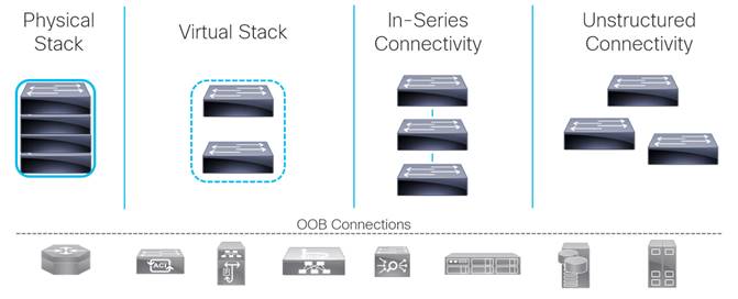
Common OOB network design practices using Catalyst
The following image illustrates common ways that we see the Catalyst switches used in an OOB network. Typical designs include physical and virtual stacks, in-series connectivity, and unstructured or individually connected switches
Limitations of Catalyst based OOB design
● Standardization and consolidation – Using Catalyst switches for the data center OOB network increase the number of hardware platforms and subsequent software versions that must be managed. This increase in HW/SW footprint also increases the number and type of hardware platforms that are covered in an onsite sparing strategy.
● Operation and management – Often managed as individual elements, and to manage Catalyst switches from a single vantage, an extra platform such as DNA center is required. This requirement introduces separate tooling that is outside of the data center span of control, prohibiting integration into Nexus Dashboard.
● Segmentation - Depending on your security policy, OOB network subnets may not be routable outside of a given site which can limit management functionality.
● Visibility – While higher-end Catalyst switches provide the ability to stack several individual switches physically or virtually so that they are managed as a single logical network element, a separate management tool (ex. DNAC) is required to gain visibility into the operational health of the devices.
● Platform function and capability – While lower-end Catalyst switches tend to look like a cost-effective option, it is important to note that entry-level switches typically do not provide the feature/function often required within the data center. Examples include a lack of redundant or modular power supplies and physical or logical stacking capability.
NextGen OOB Design
Design Overview
When designing a NextGen OOB network, it’s important to maintain the benefits that are delivered in a traditional FEX or Catalyst-based design (primarily the ability to configure multiple physical devices as a single logical element) while addressing their shortcomings both tactically and strategically. When deploying an OOB using the NextGen EVPN VXLAN design principles detailed in this white paper, we’re able to apply the many to one physical to logical element management benefit to the network, while introducing several other features and capabilities.
The NextGen OOB network design inherently builds in the following attributes, capabilities, and operational benefits:
● Secure multitenancy
● Inherent network layer segmentation
● Granular (per port) east/west traffic segmentation
● Layer 3 multi-site OOB reachability
● Management
● Governance
● Visibility
● Automation (IaC)
● Standardized functional building blocks
● Cost-conscious (platform hardware-software consolidation or sparing and so on.)
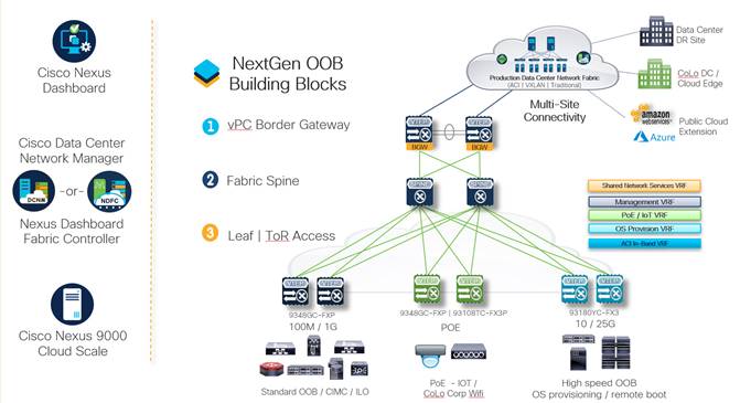
The following image illustrates how we can achieve the benefits that are listed above with a NextGen OOB design leveraging the Nexus 9000 Series switches as the switch platform, NDFC as the engineering and operational control point, and Nexus Dashboard as the single vantage point for multiple management networks, as well as internetwork orchestration and governance using Nexus Dashboard Orchestrator (NDO).
Design Security
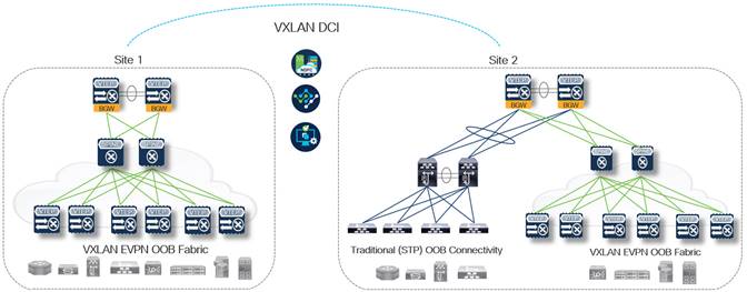
Secure Multitenancy with EVPN VXLAN
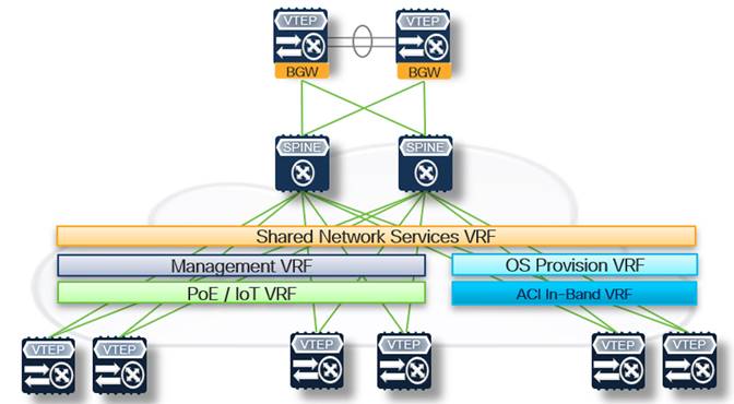
Secure multitenancy is one of the fundamental concepts inherent to the NextGen OOB design that makes it extensible, providing inherent segmentation at multiple levels. Each VRF (Layer 3 VNI) can be considered its tenant, within which we configure individual logically isolated bridge domains (Layer 2 VNI).
In the following figure, there are five different VRFs outlined as an example of how we can map a specific function within the NextGen OOB fabric to its logical network tenant. Each functional VRF may span one or more leaf pairs within the fabric depending on downstream connectivity requirements.
Note: Individual design implementation varies in how you configure segmentation, whether it be a smaller number of VRFs, each with many L2 VNIs, or a larger number of VRFs, each with few L2 VNIs.
Enhanced segmentation granularity with VXLAN PVLAN
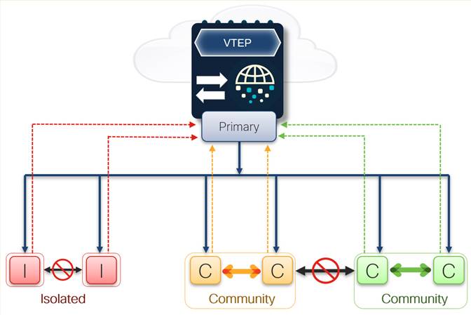
In addition to segmenting functional traffic within the fabric using VRFs and segmented bridge domains, we can add another level of east/west traffic segmentation granularity within a given L2 VNI by configuring private VLANs (PVLANs). When configuring PVLANs within the fabric, we can isolate and segment traffic down to each port connection.
This additional level of control may be desired for several reasons based on what is connecting downstream. For example, server management (ex. UCS CIMC) connections can be segmented into a specific VRF, providing segmentation or isolation within the OOB fabric, and we also know that there should be no reason a server management IP must talk to another server management IP. Using PVLANs we can configure each server management connection as an isolated port, thus prohibiting east/west connectivity within the Layer 2 VNI, only allowing north/south connectivity to the Anycast Gateway.
Private VLAN Components
● Primary VLAN
◦ Promiscuous Ports
● Secondary VLAN
◦ Segmentation of Primary VLAN
● Community
◦ Ports can forward within community
◦ Ports can forward to promiscuous (primary VLAN)
● Isolated
◦ Ports can ONLY forward to promiscuous (primary VLAN)
Design Components
Nexus 9000 Platform
The Cisco Nexus 9000 Series switches consist of two primary form factors, the modular 9500 series (available in 4, 8, and 16 slot options) and the fixed 9300 series (available in a variety of models, each providing different front-facing port connectivity options). Regardless of the form factor, all Nexus 9000 series switches are powered by Cisco silicon, marketed as the Cisco Cloud-Scale ASIC line.
Cisco Cloud-Scale ASICs provide line-rate throughput on all ports, 1/10/25/40/100/400G (zero platform over-subscription), and the ability to push line-rate telemetry directly from the ASIC, without impacting the CPU.
We can quickly determine which model Nexus 9000 Series switches are best suited to support functional OOB requirements using the following reference guide:
Reference Switch Model – 93108TC-FX3P
The Numbers (for example, 9|3|108)
● (9) First number = Switch make
● (3) Second number = Switch model/family
● (108) Third number = Max aggregate throughput (48x10G Base-T ports + 6x100G ports == 108GB Total)
The Letters (ex. TC-FX3P)
● (TC) First letter group designates the switch face plate or port connections (connection type and speed)
◦ D: Native 400-Gbps front-panel ports (QSFP-DD)
◦ Q: Native 40-Gbps front-panel ports (QSFP)
◦ Y: Native 25-Gbps front-panel ports (SFP+/SFP28)
◦ C: Native 100-Gbps front-panel ports (QSFP)
◦ L: Native 50-Gbps front-panel ports (QSFP)
◦ T: 100M*, 1Gbps, and 10Gbps (Base-T – RF45)
◦ G: 100M, 1G (Base-T – RJ-45)
● (FX3) Second letter group designates which ASIC that the switch is based on (EX, FX, FX2, FX3, GX and so on.)
● (P) If there is a letter ‘P’ at the end of the model it means that this model supports the power of ethernet (PoE)
Note: Both the 9348GC-FXP and 92348GC-X models are built for standard low speed. Base-T OOB and legacy device connections up to 1G; the 92348GC-X model does not support EVPN VXLAN which is why the second and third numbers differ slightly from the standard convention.
Purpose-specific, functional deployment examples for each Nexus 9000 Series switch in the following table are also mapped to each of the NextGen OOB design use cases detailed within the following section.
| Nexus 9000 Series Switch Model |
Connectivity/Front Facing Ports |
OOB Function |
OOB Features |
| 92348GC-X (1RU) |
48x 100M/1G Base-T (RJ-45) 4x 10/25G SFP | 2x 40/100G QSFP |
Standard ToR Switch Purpose-built, cost focused line rate switch meant for traditional RJ-45 OOB network connectivity |
Traditional networking only Does Not support EVPN VXLAN |
| 9348GC-FXP (1RU) |
48x 100M/1G Base-T (RJ-45) 4x 10/25G SFP | 2x 40/100G QSFP |
Fabric Leaf/Standard ToR Switch Purpose-built, cost focused line rate switch meant for traditional RJ-45 OOB network connectivity and UPoE capable |
Supports EVPN VXLAN configuration (secure tenancy or segmentation) |
| 93108TC-FX3P (1RU) |
48x 1/10G Base-T (RJ-45) 6x 40/100G QSFP |
Fabric Leaf/Standard ToR Switch High speed (1/10G) line rate RJ-45 connections, UPoE, and MGig capable |
Supports EVPN VXLAN configuration (secure tenancy or segmentation) |
| 93180YC-FX3 (1RU) |
48x 1/10/25G SFP 6x 40/100G QSFP |
Fabric Leaf/Fabric Border GW/Standard ToR Switch High-speed 1/10/25G line rate SFP connections Distributed port density – ToR cable plant design |
Supports EVPN VXLAN configuration (secure tenancy or segmentation) Does NOT support CloudSEC |
| 93360YC-FX2 (2RU) |
96x 1/10/25G SFP 12x 40/100G QSFP |
Fabric Leaf/Standard ToR Switch High-speed 1/10/25G line rate SFP connections Centralized port density – EoR/MoR cable plant design |
Supports EVPN VXLAN configuration (secure tenancy or segmentation) |
| 93216TC-FX2 (2RU) |
96x 1/10G Base-T 12x 40/100G QSFP |
Fabric Leaf/Standard ToR Switch High speed (1/10G) line rate RJ-45 connections Centralized port density – EoR/MoR cable plant design |
Supports EVPN VXLAN configuration (secure tenancy or segmentation) |
| 9336C-FX2 (1RU) |
36x 1/10/25/40/100G QSFP Breakout and QSA support on all ports |
OOB Aggregation/Fabric Border GW/Fabric Spine Highly customizable line rate QSFP/QSA-SFP connections |
Supports EVPN VXLAN configuration (secure tenancy or segmentation) Supports CloudSec (line rate inter-site encryption – multi-site OOB) |
Note: NXOS Release 9.2(1) or the current long-lived release [9.3(x) | 10.2(x)] highly is recommended to support both PVLAN and EVPN VXLAN vPC Border Gateway cohesive functionality
Nexus Dashboard Fabric Controller
Starting with Release 12, Cisco’s data center EVPN/VXLAN fabric management platform has undergone several changes. The most apparent is the rebranding from Data Center Network Manager (DCNM) to Nexus Dashboard Fabric Controller (NDFC). This new name better describes the purpose and evolved function of the platform as well as how it is deployed.
In addition to the updated name, the NDFC application has been re-written from the ground up to be deployed as a microservice within the Nexus Dashboard Kubernetes platform. Benefits of this new application architecture include more streamlined feature and release updates, user interface enhancements, and native integration into the One View federated vantage point.
For additional information on the changes or updates or that NDFC (from Release 12) includes, see Cisco Nexus Dashboard Fabric Controller 12 Data Sheet.
The new NDFC service architecture and deployment within Nexus Dashboard results in the following changes as compared to the previous DCNM Release 11.
Deployment
● DCNM (Release 11) - Single standalone application open virtual appliance (OVA) or redundant HA OVA pair
● NDFC (Release 12) - HA Cluster of 3 Nexus Dashboard instances each running the NDFC service
Connectivity
Beginning with NDFC version 12.1, available for download from the Cisco DC App Center, inband connectivity (fabric network) provides Layer 3 reachability to managed devices, nesting management reachability within the in-band connection, thus removing the requirement for individual physical connections dedicated for management purposes.
While an OOB network is used to manage production devices (server management through CIMC/iLO, production network devices, L4-7 service, and so on), the focus of this document is the management of the OOB network devices which facilitate management connectivity to the production devices. We recommended that management of the OOB network is configured using inband connectivity in NDFC (Release 12) to simplify the design and reduce the physical connections to manage the OOB infrastructure.
The following table compares the DCNM (Release 11) and NDFC (Release 12) interface types along with their usage specific to the NextGen OOB implementation.
| Interface Name/Type Connection Usage |
External Platform/Application Management |
OOB Network Device Management |
Inband Network Device Management/POAP |
| DCNM (v11) |
Single IP address in device Inband subnet |
Not Used for OOB device management |
Single IP address in separate subnet (Eth2) |
| NDFC (v12) |
Three IP addresses in Inband subnet |
Not Used for OOB device management |
Three IP addresses in separate (fabric) subnet |
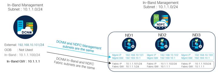
The following figure outlines an example deployment and connectivity transition from DCNM to NDFC specifically for Next-Gen OOB management and control, using inband connectivity.
With both DCNM and NDFC, two subnets are required:
● Subnet one for application and controller management (Eth0 in DCNM, Mgmt network in NDFC)
● Subnet two for inband connectivity (eth2 in DCNM, Fabric network in NDFC)
Note: The only difference in the following image is that NDFC requires two additional addresses in each subnet as there are a total of three NDFC cluster nodes.
Cisco NDFC is the management or control point for the NextGen OOB network and provides operational and lifecycle governance, heath and visibility, real-time performance, configuration automation and compliance. With NDFC managing all devices within the OOB network, the previous benefit of using FEX or switch stacks to reduce the number of logical network elements is no longer of concern.
Using NDFC we can design and configure our NextGen OOB network based on current requirements, with the flexibility to change or update the design if new requirements come to light.
With NDFC you can provision, configure, and manage EVPN VXLAN fabric elements directly connected to ToR (non-VXLAN) devices and existing hierarchical networks connected to the fabric using built-in workflows which map to the desired design outcome.
External Fabric Workflow
● Used when adding both new and existing non-VXLAN devices
● Devices within an external fabric can be monitored or managed
● If a non-fabric access device is directly connected to the fabric, add to the topology by using the External Fabric workflow along with the Automated ToR feature.
Using the External Fabrics workflow, you can unify management with the EVPN VXLAN fabric and the External (non-VXLAN) devices into a single view using a Multi-Fabric Domain (MSD fabric type).
For detailed design and configuration information on the different deployment options, see Cisco NDFC Fabric Controller Configuration Guide.
Design Considerations
The following series of figures detail three primary design and deployment models, each providing a distinct set of features and deployment considerations. You can connect each site's OOB deployments using a VXLAN-based DCI, allowing to extend OOB network connectivity to multiple sites.
In all design and deployment models, it is presumed that we use a vPC BGW design which provides flexible connectivity options, and the ability to securely and safely extend the NextGen OOB network throughout multiple sites and regions.
While it is possible to combine fabric switch roles (for example, border leaf and spine functions can be deployed on a single pair of Nexus 9000 Series switches creating a border spine role), the NextGen OOB design uses a dedicated pair of switches for both the vPC border leaf and spine functions. This is done specifically to provide the highest level of flexibility regarding what can be connected to the vPC border gateway devices, as a combined border spine role limits connectivity to Layer 3 only.
Note: For this white paper, NDFC performs the necessary protocol configurations based on the design being implemented - For a detailed review of how each of the following deployment models works for the EVPN-VXLAN protocol configuration (specific focus on the BGW function) including sample configuration and design leading practice, see NextGen DCI with VXLAN EVPN Multi-Site Using vPC Border Gateways White Paper.
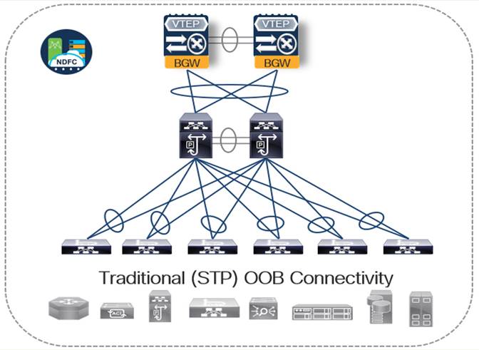
Table 1. Design Option 1 - VXLAN BGW Edge Only
| Advantages |
Disadvantages |
| ● Multi-Site OOB – The ability to stretch one or more VLANs to multiple physical locations using VXLAN without increasing the L2 blast RADIUS ● Operational Comfort – Less of a learning curve than a full EVPN VXLAN fabric ● Reduced upfront CapEx – Devices that are not part of an EVPN VXLAN fabric do not require an Advantage tier license. We are also able to make use of the 92348GC-X model which does not support EVPN VXLAN |
● Legacy Design Limitations - The OOB network continues to operate using dated protocols (STP) which require complimentary design practices such as centralized L2|L3 GW boundary and a First Hop Redundancy Protocol moved up a layer to an aggregation block ● Configuration Overhead and Complexity - Additional configuration (vPC) required to use more than 50% of the available bandwidth due to STP blocking ● Configuration Automation/Governance – While NDFC provides the ability to provision and manage both EVPN VXLAN Leafs, directly connected ToR switches and existing hierarchical switch blocks, the more diverse the end-to-end topology is, the greater the operational overhead becomes, which can diminish operational benefits gained ● Security and Risk Mitigation - Traffic separation (NOT segmentation) is based on IP subnet/VLAN and ACL configuration. |
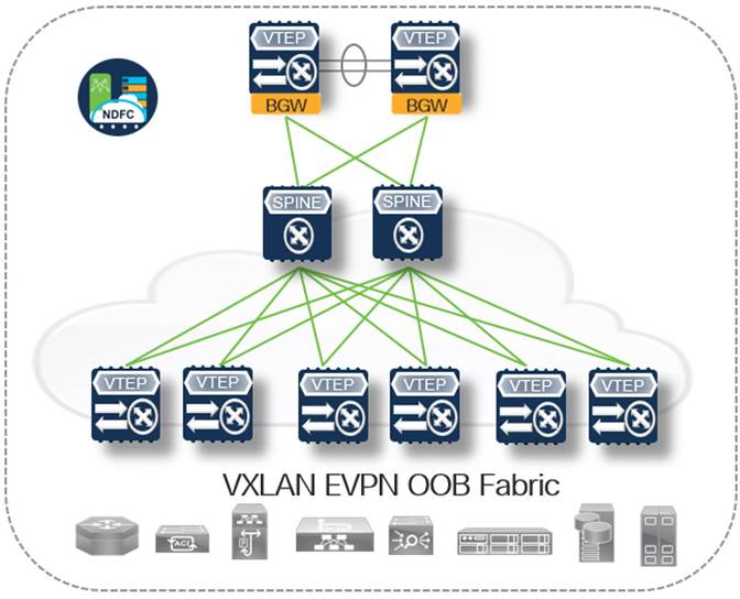
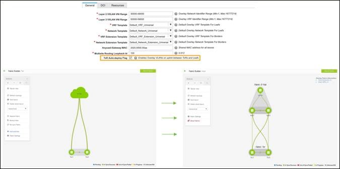
Table 2. Design Option 2 - Full EVPN VXLAN Fabric
| Advantages |
Disadvantages |
| ● Multi-Site OOB – The ability to stretch one or more VLAN/VN segments to multiple physical locations using VXLAN-based DCI ● Network Stability/Predictability (No Spanning Tree) – Routed underlay or overlay design removing spanning tree and complimentary protocol configuration | the shift in Layer 2-Layer 3 boundary down to the first hop ToR Leaf (Anycast Gateway) ● End-to-End Encryption – Ability to enable MACSec which encrypts traffic at line rate hop by hop with the site-internal fabric and CloudSec which encrypts traffic at line rate between sites (also known as multihop MACSec) ● Secure Multitenancy – Granular control over traffic segmentation and route-leaking/secure shared services and the ability to insert L4-7 services if/where required by redirecting interesting traffic (PBR) ● Granular East/West Segmentation (VXLAN PVLAN) – Per port segmentation using private VLANs, providing the ability to isolate or group OOB access connections based on functional requirements |
● Configuration Overhead – There are multiple layers of configuration required (Underlay/Overlay), most of which is more specific to service provider networking until now (BGP/VRF) which often introduces a heavier learning curve Note: While there are many configurations required for an EVPN VXLAN fabric, NDFC does it all for you and displays what configurations are applied or modified, based on your intent which ensures leading practice configuration is implanted and can also aid in learning the technology ● Slightly higher upfront CapEx requirement – EVPN VXLAN border gateway nodes require the advantage tier license which is a slight uplift from the lower-level essentials tier. |
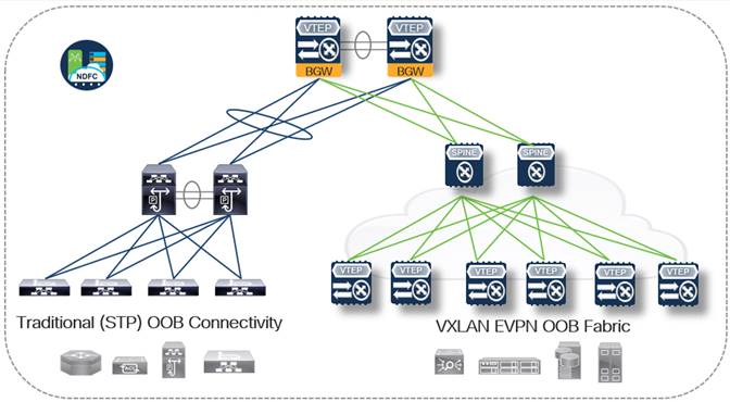
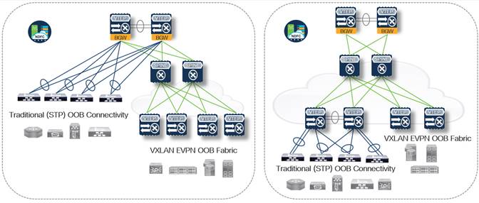
Table 3. Design Option 3 - Hybrid EVPN VXLAN and traditional VLAN/STP ToR
| Advantages |
Disadvantages |
| ● Slightly diluted variants of all Pros from Design Options 1 and 2 ● Design Flexibly – The ability to deploy either a standard STP-based ToR or VXLAN Leaf (TEP) where required |
● Slightly diluted variants of all Cons from Design Options 1 and 2 ● Duplicate Aggregation/Spine Hardware - Additional physical connections and chassis duplication at the aggregation or spine layer may be required (Option 3a) as we are standing up two functionally separate networks that come together at the border gateway (similar to DCI connectivity seen during the middle phases of a migration from a legacy STP/VLAN design to EVPN VXLAN) ● While this does introduce additional costs initially, it is important to keep in mind the additional flexibility the design offers – allowing full functional design control based on OOB connectivity requirements |
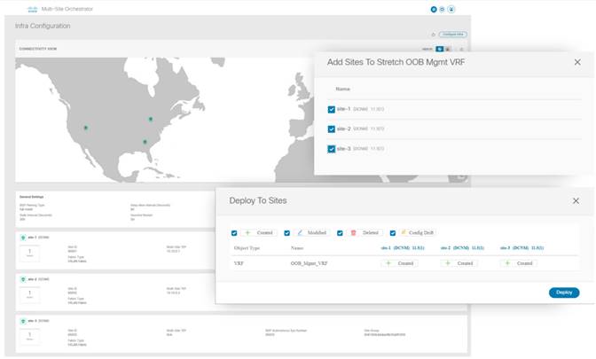
We can also connect individual site OOB fabrics as part of a multi-site connected deployment. Each site in a multi-site topology can be set up differently allowing for a highly flexible operational modality or deployment timeline.
For example, Site 1 NextGen OOB deployment may consist of a new EVPN VXLAN only fabric and can still be connected or extended as required to site 2 which may be a hybrid fabric including nonfabric ToR devices. One of the primary benefits of the flexible OOB design is the freedom to implement the functional requirements as needed without losing end-to-end feature function.
With NDFC, connecting multiple site OOB fabrics can be accomplished quickly and efficiently. The following figure displays Nexus Dashboard Orchestrator infrastructure configuration view after three individual NDFC sites are linked, and the site selection screen is configured within Orchestrator which then deploys a stretched management OOB VRF to each physical site.
Deployment Scenarios and Use Cases
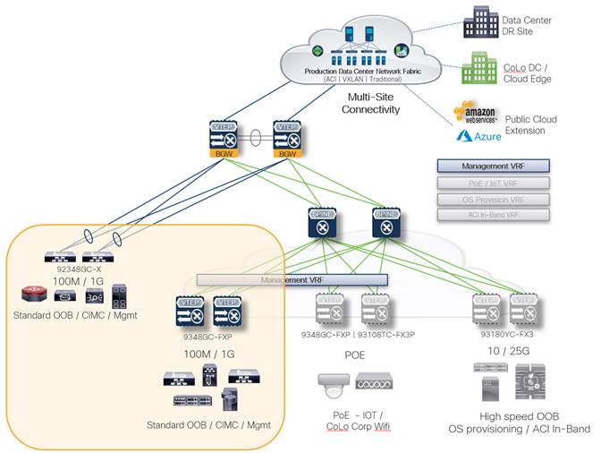
Standard OOB Connectivity
Standard OOB connectivity refers to typical low bandwidth, Base-T (RJ-45) connection to a dedicated management port or VRF on a network device, or a management (ex. UCS CIMC) connection on a server. These OOB connections are used for VTY connectivity and often for sourcing network services such as NTP, SNMP, Logging, TACACS+, and so on.
Recommended Nexus 9000 Series platforms for traditional OOB connectivity:
● Nexus 92348GC-X (if deploying as a non-VLAN ToR connected to a fabric)
● Nexus 9348GC-FXP (if deploying as leaf or VTEP within a fabric)
Note that the management VRF is extended to all switch pairs that provide Base-T (RJ-45) connectivity
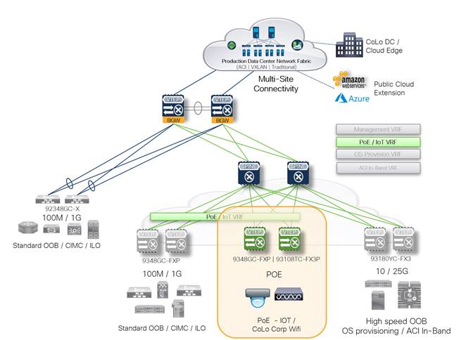
PoE and IoT Device Connectivity
In addition to traditional OOB network connectivity requirements such as those highlighted above, there are often endpoints that require the network to supply them with power. The most common example of this is the need to provide wireless network connectivity throughout a DC or CoLo space.
Using one of the Nexus 9000 Series switches listed below, we can power the wireless access points without introducing a separate make and model of switch, thus maintaining a standard hardware and software footprint.
As discussed throughout the white paper, the number of managed endpoints is only going to grow, providing several advantages about visibility and remote management, while increasing the surface area that bad actors can use for malicious purposes (for example, Ransomware, PII data mining, and physical damage). As such, we must make sure that IoT devices are fully segmented, and connectivity is tightly controlled and monitored.
An EVPN VXLAN based fabric configured and governed by NDFC can provide both the secure tenancy and granular port isolation along with persistent visibility and compliance checking that is required to ensure that the required level of segmentation is in place and operating as intended.
The two Nexus 9000 Series switches that are PoE capable (60W UPoE) are:
● Nexus 9348GC-FXP
● Nexus 93108TC-FX3P (also mGig capable)
Note: The PoE/IoT VRF is extended to all switch pairs that are PoE capable
Intent Defined Traffic Redirection and Service Insertion
Another benefit of deploying a NextGen OOB design is the ability to selectively redirect traffic using an intent-based policy within the fabric, managed by NDFC. This can be as straightforward as making sure that all traffic from a given VRF is redirected to a Next Generation Firewall (NGFW) to be scrubbed and logged. We can also engineer fairly involved intent policies using policy-based redirect (PBR) to chain multiple L4-7 services in series to accomplish a desired intent or outcome.
As we continue to learn how the EVPN VXLAN based NextGen OOB reference sets the foundation to evolve our definition of a management network and its’ abilities, there will be the potential requirement for L4-7 services such as NGFW, intrusion detection (IDS), web proxying, and even traffic load balancing to play a part in the evolved design.
Note: It is strongly recommended that the OOB design remain straightforward, using purposeful building blocks (logical and physical) deployed in a deterministic, repeatable way to maximize operability.
If there is a requirement for L4-7 service insertion and redirection to adhere to corporate governance policy, or to accomplish a design outcome such as external audit visibility and logging, the flexibility built into the fabric and the ease of deployment and management can be provided by NDFC.
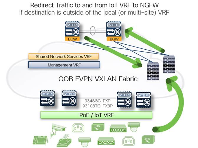
A common use case for L4-7 redirection is the requirement to scrub traffic to and from a given network that is not inherently trusted – a VRF used specifically to segment IoT devices for example. In this instance, we can define interesting traffic using several attributes and enforce a policy that mandates traffic to and from any IoT or non-trusted IP enable endpoint is redirected to an NGFW such as the Cisco Firepower series.
It is also possible to configure a fail-open or fail-closed policy within the network (based on service node reachability) to help ensure that no traffic is passed without adhering to policy governance.
As depicted by the arrows in the following figure, incoming traffic that is not established does not pass through the NGFW – redirecting defined, attribute matched traffic to the NGFW provides an additional level of security and control by enabling a separate operational team (in this case, the security team) with the ability to manage policy on the firewalls independently of the network infrastructure.
EVPN Service Redirection and Detailed PBR Configuration Reference
For information about EVPN VXLAN PBR and Service Redirection information, including deployment modes, resource utilization, configuration examples and best practices, see Layer 4 to Layer 7 Service Redirection with Enhanced Policy-Based Redirect White Paper.
For configuration information and verified scalability specific to L4-7 service insertion, see Cisco Nexus 9000 Series Switches Configuration Guides.
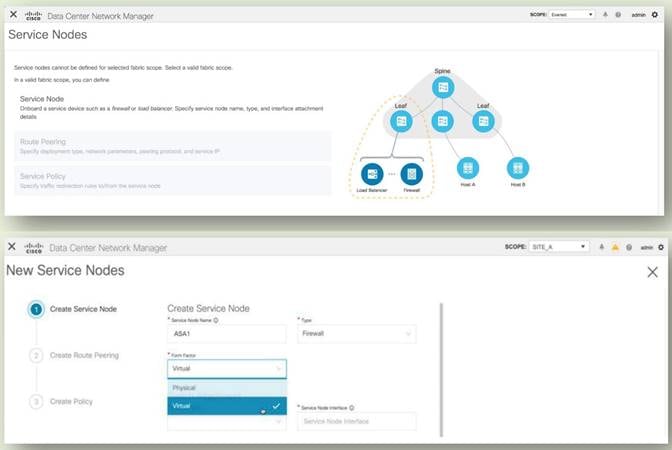
Adding a service node such as a firewall to the OOB fabric is now easier and more efficient than ever. NDFC has built-in workflows and intent-focused deployment helps to onboarding and configure service nodes (ex. NGFW) within the OOB fabric.
For information about configuration and guidelines for service node insertion and redirection (PBR), see Chapter: L4-7 Services in Cisco NDFC Fabric Controller Configuration Guide.
Specialized and Business Driven Deployment
In addition to traditional OOB network connectivity requirements, powered endpoint, and secure IoT connectivity, we can now expand the role of the OOB network to meet new and sometimes unique business-driven requirements by simply adding a different model switch pair building block to the fabric. This new building block can then be logically segmented and utilized for one or more functional purposes requiring the same type of front port connectivity (both examples below would require higher speed 10G connectivity).
High-speed Bare Metal provisioning
One example of a specialized or business-driven OOB requirement can be the need for high-speed (10G) OOB connectivity used for bare metal provisioning new servers as part of an automated workflow. To provision a server from scratch that we must first transfer the operating system .iso file to the server, these files can be hundreds of GB. Do not use an antiquated OOB network where there is 100Mbps or 1Gbps connection and a massive broadcast domain or blast radius (over 1,000 endpoints in a /22 subnet). This traditional design results in unforeseen issues with protocols that require the use of data link layer- broadcast traffic (for example, PXE boot or DHCP).
Adding a Nexus 9300 10/25G server access leaf pair to the secure, flexible OOB network eliminates all these potential issues, providing line rate connectivity directly to each bare metal host. And because we include this unique business-driven functionality as part of the EVPN VXLAN fabric, we add another layer of security to our environment, ensuring new servers are segmented from initial power on until they are fully provisioned and updated, patched, and ready to join the production.
Note: The provisioning, updating, patching, and then moving to the production process including a change to the logical network connectivity (such as an OS Provisioning VRF) can be part of an automated workflow using automation tools such as Ansible or Terraform as part of an Infrastructure as Code CI-CD pipeline.
Segmented InBand network connectivity
The second example of a specialized use case allows to securely extend connectivity to a production ACI inband network. Cisco Nexus Insights is a day 2 operations tools suite that ingests line rate hardware telemetry from all the Nexus 9000 Series leaf switches within a single fabric, or multiple fabrics, and requires a certain amount of computing, memory resources, and high disk I/O capability to ingest, and munge the telemetry data in real-time, providing next-level insights and operational data inclusive of on every packet that traverses the production fabric. Considering the resource requirements, it is recommended that the Insights service (deployed as a service on Nexus Dashboard) must be deployed in a physical appliance cluster that is physically attached to the production ACI inband network.
To add a higher degree of flexibility to the Nexus Dashboard physical cluster, securely extend the connectivity to the production ACI Inband network using a dedicated VRF within the NextGen OOB network.
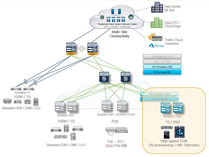
Note: While the sample design below outlines a separate VRF for the high-speed OS provisioning and inband connectivity functions (including hardware telemetry streaming), it would also be perfectly acceptable to configure this as a single High-Speed functional VRF with the OS provisioning and inband traffic separated by individual Layer 2 VNI networks
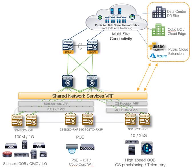
Common Multi-Site Infrastructure for Shared Network Services
The ability to extend the OOB network securely and safely to multiple physical sites also provides the ability to centralize common network services such as NTP, AAA/TACACS, SNMP, and logging. Centralizing common network services enables to maintain a single standard throughout the end-to-end data center network.
This also allows for centralized or standardized network service configuration deployed in a highly available manner across one or more physical sites. For example, provide NTP services from primary, secondary, and tertiary servers that are each physically located within different physical sites, while all connected via the same OOB network. This functionality can be useful as the definition of a data center continues to evolve, becoming a more distributed collection of resources deployed across a multitude of floor tiles.
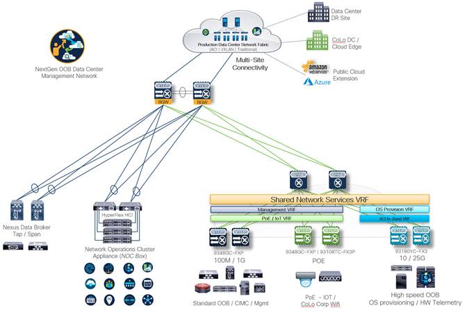
Building Modularity and Secure Segmentation
The NextGen OOB design provides technology building blocks to get the desired outcome (segmentation or standard management OOB or Multi-Site OOB connectivity or specialized connectivity requirements and so on), you must build the foundation and scale out using the building blocks that deliver the required outcome.
The following figure illustrates how the NextGen OOB design is applied inclusive of the use cases outlined above, and tangential operational technologies such as Nexus Dashboard Data Broker Tap/Span switches and a centralized network operations cluster appliance (NOC box) that can be purpose-built to host virtualized production appliances, management platforms, simulators, modeling labs. This also provides a general-purpose beachhead for the network team to test new products.
Ongoing Operation, Automation, and Visibility
Fabric Operation and Automation
As explained in the earlier sections, Cisco NDFC provides a single control point for the NextGen Out-of-Band network, allowing the ability to configure and manage both EVPN VXLAN as well as traditional STP-based devices configurations.
NDFC also facilitates software release management and general FCAPS (Fault, Configuration, Accounting, Performance, and Security) monitoring and visualization for the end-to-end network. NDFC accommodates 3rd party tools and service platforms, such as ServiceNow (ITSM) and Infoblox (IPAM).
In addition to the automated fabric provisioning, ToR deployment, and FCAPS-aligned management functions, two NDFC features that are particularly useful when managing OOB networks include:
● Interface Groups provides the ability to deploy common interface configurations for like connections.
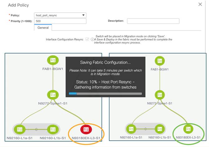
● Host Port ReSync allows you to change port configuration outside of NDFC (device CLI) and sync the configuration back to NDFC from the OOB switch.
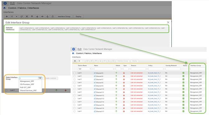
Note: The figure above highlights an additional benefit realized with NDFC – The ability to pre-provision interface group standards to ports before they are connected.
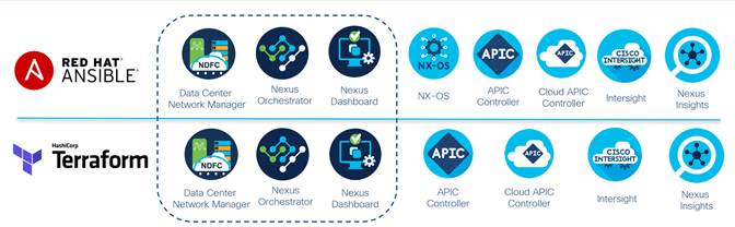
NDFC can be configured using external automation toolsets such as Ansible or Terraform, and as such can integrate into infrastructure as code (IaC) initiatives, allowing for incorporation into larger orchestrated workflows within a CI-CD pipeline. The following figure highlights current Cisco data center platform support for both Ansible and Terraform.
Cisco Nexus Dashboard
Cisco Nexus Dashboard is the platform that binds everything related to Cisco data center networking together, delivering a single vantage point (a single login URL) for all things Day 1 Engineering, Day 2 Operations, and Day 0 Automation (IaC).
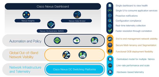
At its core, Nexus Dashboard is a Kubernetes cluster managed as an appliance that provides the following.
● Connects to your DCN fabric control points (Cisco ACI or NDFC)
● Hosts the latest version of Cisco’s EVPN VXLAN controller, Nexus Dashboard Fabric Controller
● Hosts the Cisco day-2 operations and engineering tool suites Nexus Dashboard Insights (NI+NAE), Orchestrator, and Data Broker services
● Integrates with 3rd party toolsets and automation services including ServiceNow (ITSM), Infoblox (IPAM), Ansible, and Terraform (Infrastructure as Code)
● Facilitates integration between DCN tooling and other Cisco operational platforms including Intersight, DNA Center, vManage, AppDynamics, and ThousandEyes.
The fundamental purpose of the Nexus Dashboard platform is to support and enable full lifecycle automation within the data center network regardless of where the workload resides or is moving to. Also, with 3rd party integration partners like ServiceNow providing IT Service Management (ITSM) governance, NDFC provides full visibility into current operations (event or incident management) and automates tasks and management-related workflows which follow a task-specific workflow (raising a ticket, collecting specific information, and distributing as required).
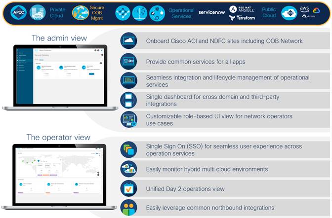
End-to-End Visibility and Operational Vantage
Cisco Nexus Dashboard advances engineering, management, visibility, and operational capabilities even further, by providing a single, federated vantage point for all data center network fabrics (ACI/NDFC) as well as orchestration and operational toolsets including Nexus Dashboard Orchestrator (formerly known as MSO), Insights, and Data Broker services.
Cisco Nexus Dashboard is flexible in how it can be deployed, including a physical cluster appliance, on-premise virtual appliance, and public cloud-hosted virtual appliance. This allows for a right-sized deployment means and sizing specific to your environment and usage.
Cisco delivers Nexus Dashboard in a cloud-native as-a-service consumption model, similar to Intersight (https://intersight.com/help/saas/getting_started/overview).
By incorporating the NDFC-managed OOB network into Nexus Dashboard, we now provide:
● Single view or launch point federated across multiple dashboard instances (OneView)
● Control access and feature/function permissions based on administrative and operational security policy requirements using LDAP, TACACS, and RADIUS
● Integration with Nexus Dashboard Orchestrator for multi-region stitching
● Integration with Cisco Intersight for additional visibility and correlated feature development
● Integration with 3rd party tools and service platforms such as ServiceNow (ITSM) and Ansible/Terraform (IaC) for more enrichment and functionality
Business Outcome Focused and Operable Design
As application workload continues to become more distributed, sourcing applications focusing on business outcomes such as time to market (CNF/hybrid cloud), end-user experience (colocated or geolocation onboarding), and regulatory compliance (geolocation data sovereignty); there is a resulting requirement to provide consistent, secure external management connectivity regardless of the floor tile.
Using the Nexus 9000 Series switches with Nexus Dashboard Fabric Controller provides the ability to deploy a secure, flexible, NextGen out-of-band data center management network with features tailored to your business outcome-based requirements, all governed from a single operational vantage point.
Additional Information
Related Product Information
Cisco Nexus 9000 Data Center Switching Platform
https://www.cisco.com/c/en/us/products/switches/nexus-9000-series-switches/index.html
Cisco Nexus Dashboard Fabric Controller
Cisco Nexus Dashboard Platform
https://www.cisco.com/c/en/us/products/data-center-analytics/nexus-dashboard/index.html
Cisco Intersight
https://www.cisco.com/c/en/us/products/cloud-systems-management/intersight/index.html
Design Guides/White Papers
VXLAN EVPN Multi-Site Design and Deployment White Paper
NextGen DCI with VXLAN EVPN Multi-Site Using vPC Border Gateways White Paper
Layer 4 to Layer 7 Service Redirection with Enhanced Policy-Based Redirect White Paper
A Modern, Open and Scalable Fabric – VXLAN EVPN
https://www.cisco.com/c/dam/en/us/td/docs/switches/datacenter/nexus9000/sw/vxlan_evpn/VXLAN_EVPN.pdf
Cisco Press Books
Building data centers with VXLAN BGP EVPN (Cisco NX-OS Perspective)
https://www.ciscopress.com/store/building-data-centers-with-vxlan-bgp-evpn-a-cisco-nx-9781587144677
Legal Information
Cisco and the Cisco logo are trademarks or registered trademarks of Cisco and/or its affiliates in the U.S. and other countries. To view a list of Cisco trademarks, go to this URL: www.cisco.com/go/trademarks. Third-party trademarks mentioned are the property of their respective owners. The use of the word partner does not imply a partnership relationship between Cisco and any other company. (1110R)
Any Internet Protocol (IP) addresses and phone numbers used in this document are not intended to be actual addresses and phone numbers. Any examples, command display output, network topology diagrams, and other figures included in the document are shown for illustrative purposes only. Any use of actual IP addresses or phone numbers in illustrative content is unintentional and coincidental.
© 2022 Cisco Systems, Inc. All rights reserved.