Layer 4 to Layer 7 Service Redirection with Enhanced Policy-Based Redirect White Paper
Available Languages
Bias-Free Language
The documentation set for this product strives to use bias-free language. For the purposes of this documentation set, bias-free is defined as language that does not imply discrimination based on age, disability, gender, racial identity, ethnic identity, sexual orientation, socioeconomic status, and intersectionality. Exceptions may be present in the documentation due to language that is hardcoded in the user interfaces of the product software, language used based on RFP documentation, or language that is used by a referenced third-party product. Learn more about how Cisco is using Inclusive Language.
Prerequisites
This document assumes that the reader is familiar with the configuration of VXLAN BGP EVPN data center fabric. The VXLAN BGP EVPN fabric can be provisioned using Cisco® Data Center Network Manager (DCNM). This document also assumes the end user is familiar with the policy-based routing constructs.
Today, insertion of service appliances (also referred to as service nodes or service endpoints) such as firewalls, application delivery controllers, TCP optimizers, intrusion prevention systems and intrusion detection systems, are needed to secure and optimize applications within a data center. Typically, these Layer 4 to Layer 7 (L4-L7) service appliances are not inserted individually but as a chain. Traditional ways of accomplishing chaining of these service nodes include defining routing rules to influence the traffic path or using Policy-Based Routing (PBR).
This routing approach involves redirecting traffic to service appliances and forwarding all the traffic along the same path. While this approach works, all traffic traverses the service nodes, making them a potential bottleneck.
Alternatively, PBR can be used to selectively redirect traffic. The challenge with service chaining using PBR is that it requires the user to create unique policies per node and manage the redirection rules manually across all the nodes in the chain. Also, given the stateful nature of the service nodes, the PBR rules must ensure symmetry for the reverse traffic, and this adds additional complexity to the configuration and management of the PBR policies.
Further, in order to cater to the exponential growth in traffic, service chains need to scale up. Even though multiple service nodes of a given type are provisioned, efficient load-balancing mechanisms are required to regulate and distribute the traffic flowing toward these appliances. While PBR helps to some extent, it cannot entirely solve the problem.
A comprehensive solution involving selective traffic redirection along with load balancing is required. There is a need to empower users with the flexibility to influence such traffic flows with a simplified workflow to onboard service nodes, create traffic chains and load-balancing rules, and also ensure symmetry for reverse traffic.
Cisco Nexus® 9000 NX-OS Enhanced Policy-Based Redirect (ePBR) is intended to help solve the challenges described above. ePBR in the Elastic Services Redirection (ESR) umbrella, provides the capability to selectively redirect and load-balance traffic across a data center network. This includes a data-center design using a VXLAN with BGP EVPN control plane with a distributed anycast gateway, as well as a three-tier core, aggregation/distribution, and access deployment with a centralized gateway.
ePBR completely automates the service chaining capability by creating multiple policies and by enabling hop-by-hop traffic steering using policy-based routing/redirection policies. These policies enforce traffic redirection by monitoring service-element health and reachability.
ePBR achieves service chaining without adding additional headers, and thus avoids any increased latency. All of the above is achieved at line rate, without any impact to throughput or performance. With the introduction of ePBR, the entire service onboarding, appliance monitoring using advanced probing mechanisms, service redirection, and load balancing are made flexible and easy to deploy.
Table1 summarizes the hardware, software, and licensing requirements for the Cisco Nexus 9000 Series Switches that provide ePBR capability.
Table 1. Minimum hardware, software and licensing requirements for ePBR
| Item |
Requirement |
| Cisco NX-OS hardware |
● Cisco Nexus 9300 EX platform
● Cisco Nexus 9300 FX platform
● Cisco Nexus 9300 FX2 platform
● Cisco Nexus 9300 FX3 platform
**
● Cisco Nexus 9300 GX platform
**
● Cisco Nexus 9500 platform with X9700-EX line card
*
● Cisco Nexus 9500 platform with X9700-FX line card
*
|
| Cisco NX-OS software |
Cisco NXOS Software Release 9.3(5) or later |
| Cisco NX-OS license |
Cisco NX-OS Advantage package |
ePBR currently supports the following deployment options with both IPV4 and IPV6 service endpoints:
● Fabric-based setup with VXLAN EVPN and appliances hosted on service leaves (Figure 1*).
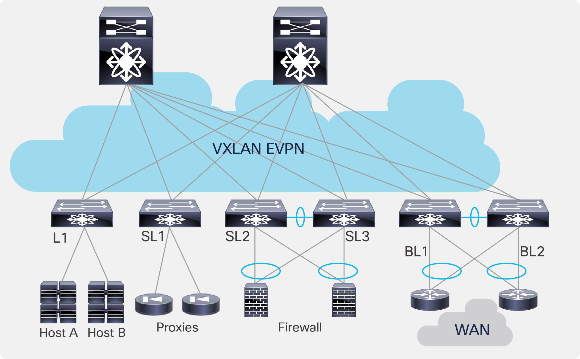
Fabric-based setup with VXLAN EVPN
● Traditional centralized gateway deployment (Figure 2).
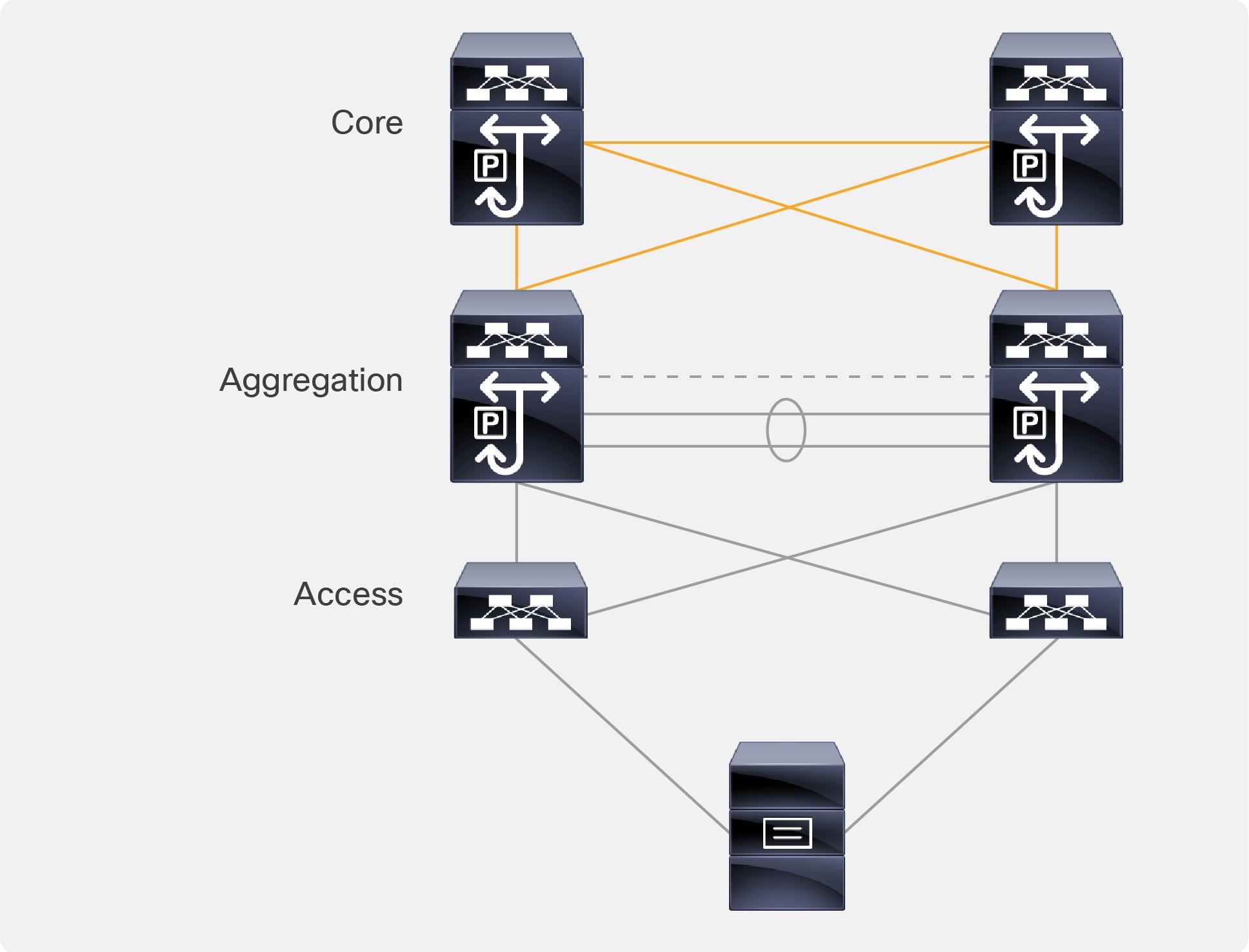
Traditional centralized gateway deployment
ePBR uses a combination of PBR with customized, bucket-based load sharing to achieve its load-balancing and traffic-steering capabilities. Once the user defines a policy with service chaining and load-balancing rules, ePBR automatically creates multiple PBR policies and applies them on the service interface belonging to the service nodes, and also creates IP SLA–based probes to monitor the health of the service nodes. Refer to the use cases for detailed configuration examples.
● Prior to feature “epbr” enablement, feature “pbr” and feature “sla sender” need to be enabled as a prerequisite.
● In the case of a fabric-based deployment with VXLAN EVPN, feature HMM (host mobility manager) is required to track the locality of the service endpoint in the fabric.
● All redirection rules are programmed in ACL TCAM using the ingress RACL region. This region needs to be carved and allocated prior to the application of ePBR policies.
The ePBR configuration consists, essentially, of four simple steps:
Step 1: Onboard the service appliance
Step 2: Create the traffic-selection rules
Step 3: Define the ePBR traffic-redirect policy
Step 4: Apply the ePBR policy on the relevant interfaces
Step 1: Onboard the service appliance
This step enables the definition of service and its endpoints. The service-endpoint is the IP address of the service node itself, which ePBR in turn utilizes as a next-hop to redirect the traffic. The service interface is the SVI on the switch facing the service node. The reverse IP refers to the second arm of the service node. For service nodes that are single-arm, define the reverse IP with the same parameters as the service endpoint.
The following aspects of a service can be defined by the user:
1) IPV4/IPv6 address of the service endpoint along with reverse IP.
2) Forward and reverse interface details for single and dual-arm appliances, respectively.
3) Tenant or VRF membership.
4) Probing mechanism with flexible timers to monitor health of nodes.
Note: A variety of probes, such as ICMP, TCP, UDP, HTTP, DNS, and user-defined custom probes, are supported. The source loopback interface can be specified to receive the probe responses.
5) Additional service endpoints in the case of an appliance cluster.
Service-definition example for an active/active firewall cluster
epbr service FIREWALL_CLUSTER
probe icmp frequency 4 timeout 2 source-interface loopback9
vrf TENANT_A
! fw1 definition
!! Interface facing the firewall
service-endpoint ip 172.16.1.200 interface VLAN100
probe icmp frequency 4 timeout 2 source-interface loopback9
!!! Reverse interface applies for two arm device
reverse ip 172.16.2.200 interface VLAN101
probe icmp frequency 4 timeout 2 source-interface loopback10
!fw2 definition
service-endpoint ip 172.16.1.201 interface VLAN100
reverse ip 172.16.2.201 interface VLAN101
Step 2: Create the traffic-selection rules
Using an Access Control List (ACL), the user must define traffic that needs to be redirected. Users can match application traffic using a source IP, a destination IP, and L4 ports to define redirection rules. Only Access Control Entries (ACEs) that are prefix-based and use permit method are supported in the ACL. ACEs with any other method (such as deny or remark) are ignored.
Example for ACL creation:
# Custom_app rule1
ip access-list custom_app
10 permit tcp 172.16.10.0/24 eq 7800 any
20 permit tcp 192.168.20.0/24 eq 7800 any
#Web based application rule2
ip access-list web
10 permit tcp 172.16.10.0/24 any eq 80
20 permit tcp 192.168.20.0/24 any eq 80
Step 3: Define the ePBR traffic-redirect policy
This step enables the definition of ePBR traffic redirection policy, which gives the user the flexibility to create a service chain along with various fail-action mechanisms on service health failure. The following properties of ePBR policy can be defined by the user:
1) Predefined match ACLs (refer to step 2). The ePBR policy supports multiple ACL match definitions
a. Redirect: default action for matching traffic and redirecting to a service chain
b. Drop: match specific traffic and drop the traffic on the incoming interface
c. Exclude: exclude certain traffic flows from the service chain on the incoming interface
2) Load-balance method (The section “Load balancing using ePBR” in this document explains how load balancing is achieved in ePBR.)
a. Source IP or destination IP based
b. Number of buckets to be configured in order to have granular load balancing of traffic
3) Service prefixed by sequence number to redirect selected traffic of interest to a service or across a chain
4) Fail-action methods to invoke on service reachability failure
a. Forward: default option where traffic should use the regular routing tables
b. Drop: traffic is dropped when service becomes unreachable
c. Bypass: traffic is redirected to the next service sequence when there is a failure of the current sequence
Note: In the case of an appliance cluster, the fail-action mechanism will be invoked only when all service endpoints that belong to a service fail.
Example for policy definition:
epbr policy Tenant_A-Redirect
match ip address WEB !!! ACL matches web traffic
load-balance method src-ip
10 set service FIREWALL fail-action drop
20 set service TCP_Optimizer fail-action bypass
match ip address custom_app !!! ACL matches custom APP traffic
load-balance method src-ip
10 set service FIREWALL fail-action drop
Step 4: Apply the ePBR policy on the relevant interfaces
Once the ePBR policy is defined (refer to step 3), the policy needs to be applied on the ingress interface through which traffic flows into the fabric. Essentially, the policy is applied to any ingress interface from which the chaining starts. In the case of a VXLAN EVPN fabric, we would also need to apply the policy to all the L3 VNI interfaces on the service leaves hosting the appliances.
In order to maintain the traffic flow symmetry in the opposite direction, the end user would just need to apply the policy on the relevant interface along with the “reverse” keyword. If the reverse policy is enabled, ePBR autogenerates reverse rules for return traffic. It reverses the order in which the traffic traverses the chain, and also reverses the ACL matching the traffic.
Example for policy application
interface Vlan 2010
!L3 VNI SVI
epbr ip policy Tenant_A-Redirect
epbr ip policy Tenant_A-Redirect reverse
ePBR load balances by using a bucket-based load-sharing algorithm using a source or destination IP address. In the load-balance command, we provide the flexibility to the end user to specify the number of buckets, which allows the user to specify how granular the traffic should be distributed (refer step 3). If this option is not configured internally, we create default buckets higher or equal to the number of service nodes configured as part of the ePBR service.
The example below shows a bucket distribution of 2. An IP address ending with binary 00 is redirected to bucket 1, 01 to bucket 2, 10 to bucket 3, and 11 to bucket 4.
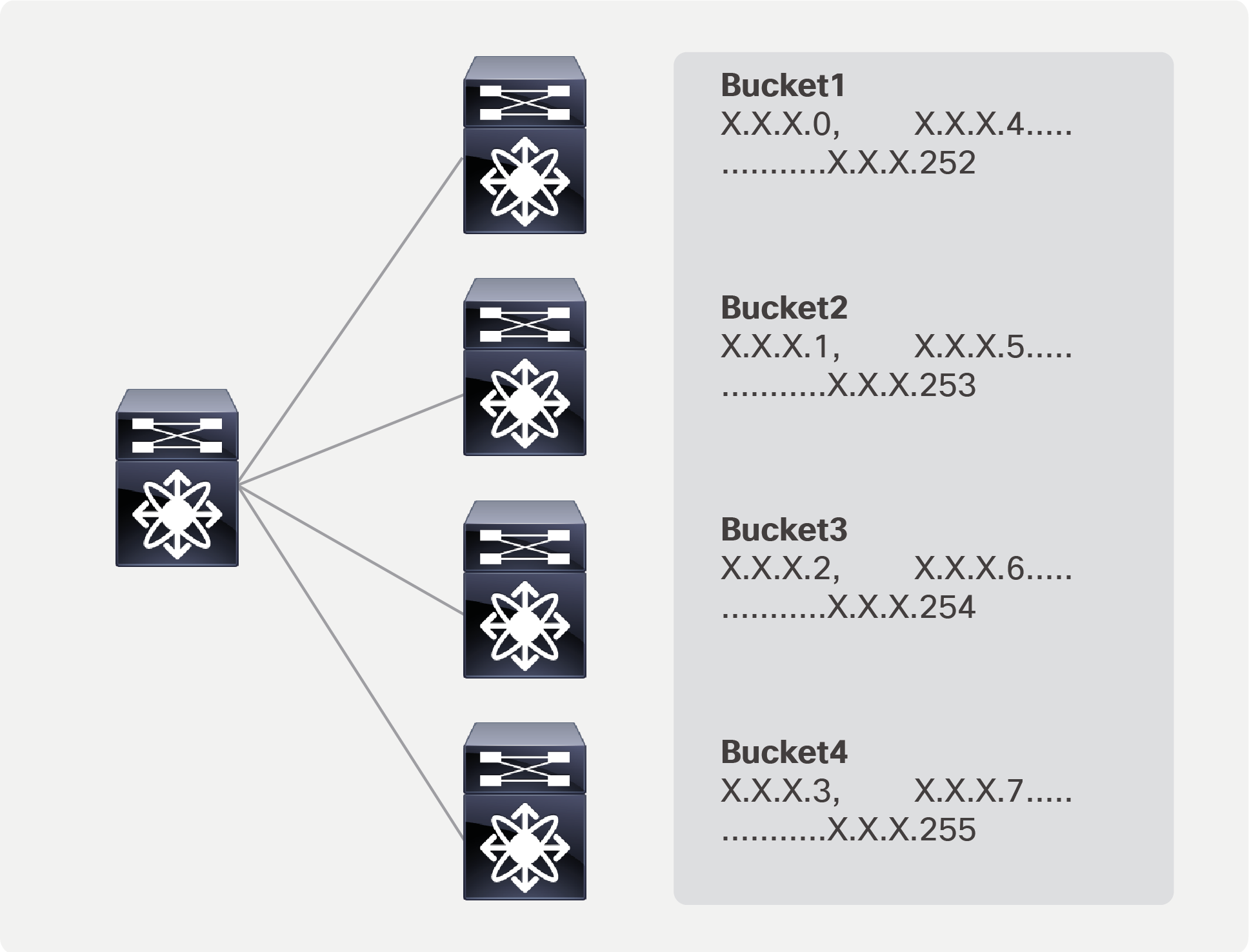
Load balancing using ePBR
Example for load balancing:
epbr service fw_cluster
! 4 firewalls in this cluster to which the traffic needs to be load-balanced
service-end-point ip 1.1.1.1
service-end-point ip 2.2.2.2
service-end-point ip 3.3.3.3
service-end-point ip 4.4.4.4
ip access-list acl1
10 permit ip 10.1.1.1/24 20.1.1.1/24
epbr policy p1
match ip address acl1
load-balance buckets 8 method src-ip
10 set service fw_cluster
interface Vlan100
epbr ip policy p1
Autogenerated access list based on the algorithm to segregate traffic into multiple buckets
IP access list epbr_p1_1_fwd_bucket_1
10 permit ip 10.1.1.0 0.0.0.248 20.1.1.1 0.0.0.255
IP access list epbr_p1_1_fwd_bucket_2
10 permit ip 10.1.1.1 0.0.0.248 20.1.1.1 0.0.0.255
IP access list epbr_p1_1_fwd_bucket_3
10 permit ip 10.1.1.2 0.0.0.248 20.1.1.1 0.0.0.255
IP access list epbr_p1_1_fwd_bucket_4
10 permit ip 10.1.1.3 0.0.0.248 20.1.1.1 0.0.0.255
IP access list epbr_p1_1_fwd_bucket_5
10 permit ip 10.1.1.4 0.0.0.248 20.1.1.1 0.0.0.255
IP access list epbr_p1_1_fwd_bucket_6
10 permit ip 10.1.1.5 0.0.0.248 20.1.1.1 0.0.0.255
IP access list epbr_p1_1_fwd_bucket_7
10 permit ip 10.1.1.6 0.0.0.248 20.1.1.1 0.0.0.255
IP access list epbr_p1_1_fwd_bucket_8
10 permit ip 10.1.1.7 0.0.0.248 20.1.1.1 0.0.0.255
Changes and modification to service nodes or policy
ePBR sessions enable users to make modifications to ePBR policy non-disruptively. Using this capability, we are able to onboard new service nodes efficiently and make modifications to existing service chains with minimal traffic disruption.
ePBR sessions allow addition, deletion, or modification of the following aspects of in-service policies or services.
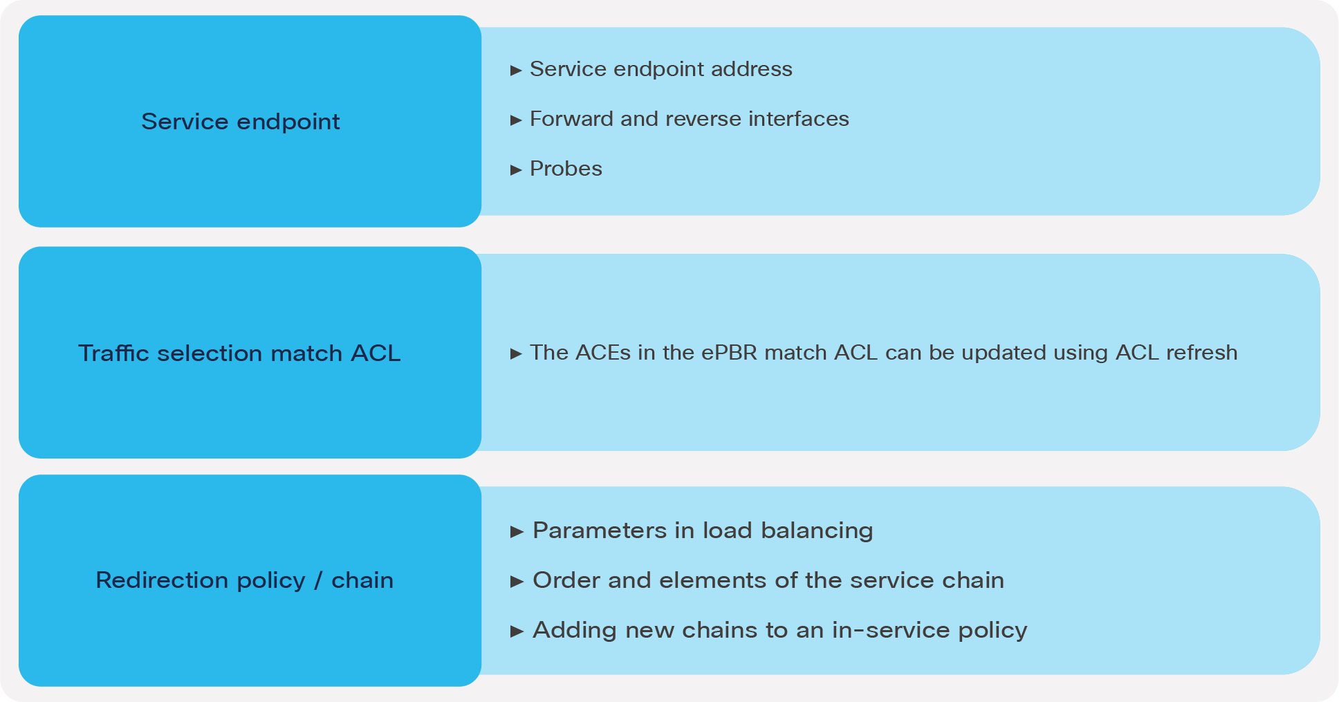
Non disruptive in-service config updates
Automating ePBR configuration using model-driven programmability
To configure, update, and automate the ePBR configuration in Cisco Nexus 9000 Series Switches, the following network configuration protocols are supported using XML and JSON payloads:
● REST
● NETCONF
● RESTCONF
External scripts and tools can be used to leverage the above configuration protocols to automate ePBR network provisioning. The “References” section at the end of this document includes a link to the ePBR NX-API REST user guide.
Note: All of the use cases listed below are supported on both VXLAN EVPN distributed anycast gateway deployment as well as core, aggregation, and access centralized gateway deployment.
Use case 1: ePBR for multidevice service chaining
This use case covers a deployment model where different applications in the data center need to traverse different service chains or service nodes.
Use case 1 deployment example:
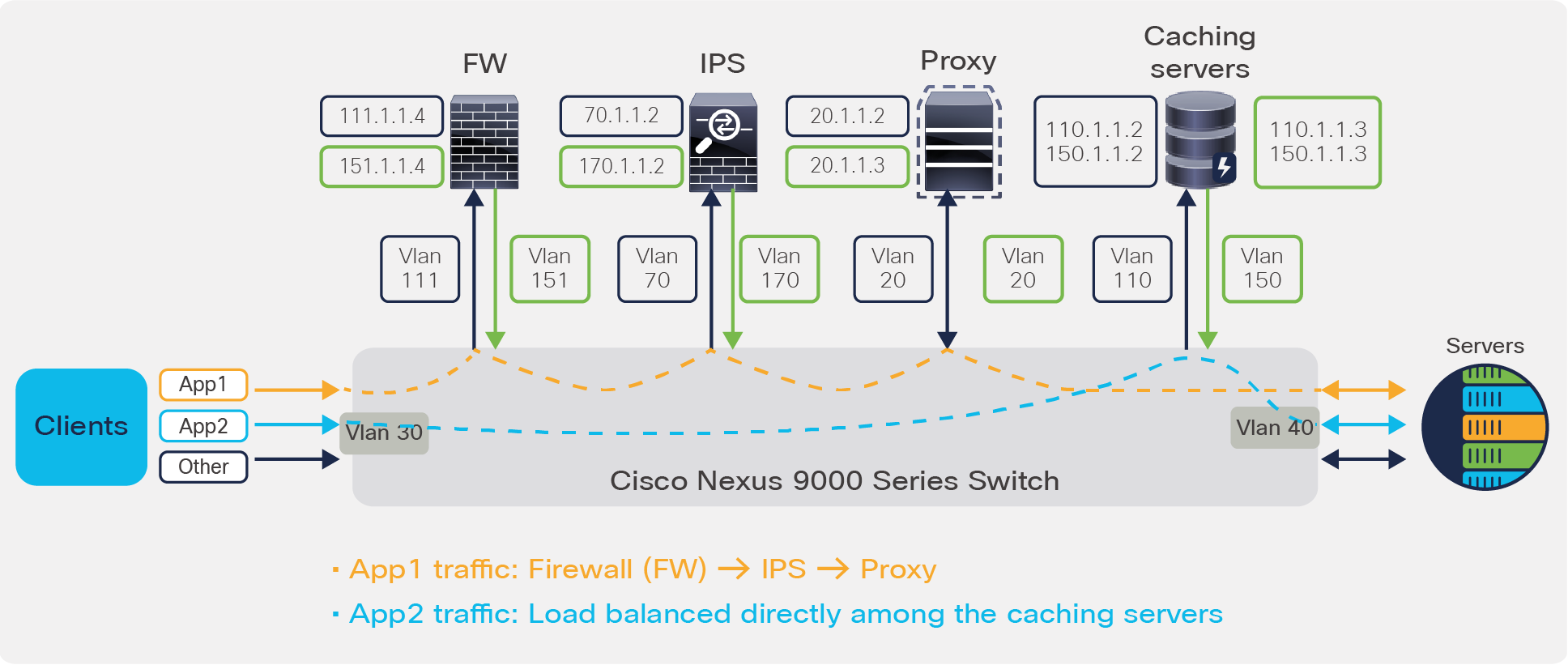
The deployment here is that of a centralized gateway model (non VXLAN). In this scenario, client traffic for application App1 needs to be redirected to the firewall, IPS, and proxy and then sent to their destination, whereas application App 2 only requires redirection and load balancing to the cluster of caching services. The rest of the traffic must simply follow the default routing path.
Use case 1: ePBR for multidevice service chaining
Configuration:
Step 1: Onboard the appliances
epbr service firewall
service-end-point ip 111.1.1.4 interface Vlan111
probe icmp source-interface loopback0
reverse ip 151.1.1.4 interface Vlan151
probe icmp source-interface loopback1
epbr service ips
service-end-point ip 70.1.1.2 interface Vlan70
probe udp 45000
reverse ip 170.1.1.2 interface Vlan170
probe udp 45001
epbr service proxy
service-interface Vlan20
probe http get index.html
service-end-point ip 20.1.1.2
reverse ip 20.1.1.3
epbr service caching_servers
! traffic will be load-balanced between the servers
! server1
service-end-point ip 110.1.1.2 interface Vlan110
probe icmp source-interface loopback0
reverse ip 150.1.1.2 interface Vlan150
probe icmp source-interface loopback1
! server2
service-end-point ip 110.1.1.3 interface Vlan110
probe icmp source-interface loopback0
reverse ip 150.1.1.3 interface Vlan150
probe icmp source-interface loopback1
Step 2: Create traffic selection rules
Here 2 different match criteria (app1 and app2) are defined based on which our service redirection takes place.
ip access-list app1
10 permit tcp 172.16.10.0/24 eq 7800 any
20 permit tcp 192.168.20.0/24 eq 7800 any
ip access-list app2
10 permit tcp 172.16.10.0/24 any eq www
20 permit tcp 192.168.20.0/24 any eq www
Step 3: Define ePBR traffic redirect policy
In this policy defined below, on the event of firewall failure, the traffic is dropped. On the event of IPS failure, traffic bypasses this service element and is forwarded to the next element in chain which is Proxy in this case. Finally, on the event of Proxy failure, traffic is forwarded through routing table, which is also the default fail-action mechanism
epbr policy redirect_and_loadbalance
statistics
match ip address app1
! Traffic matching app1 takes FWÒIPSÒProxy chain
10 set service firewall fail-action drop
20 set service ips fail-action bypass
30 set service proxy fail-action forward
match ip address app2
! Traffic matching app2 is load-balanced across caching servers
load-balance buckets 8 method src-ip
10 set service caching_servers
Step 4: Apply the ePBR Policy on relevant interfaces
interface Vlan30
!forward policy applied to ingress interface facing clients
no shutdown
ip address 30.1.1.1/24
ipv6 address 2030::1/24
epbr ip policy redirect_and_loadbalance
interface Vlan40
! Reverse policy applied to egress interface facing server farm for reverse flow
no shutdown
ip address 40.1.1.1/24
ipv6 address 2040::1/24
epbr ip policy redirect_and_loadbalance reverse
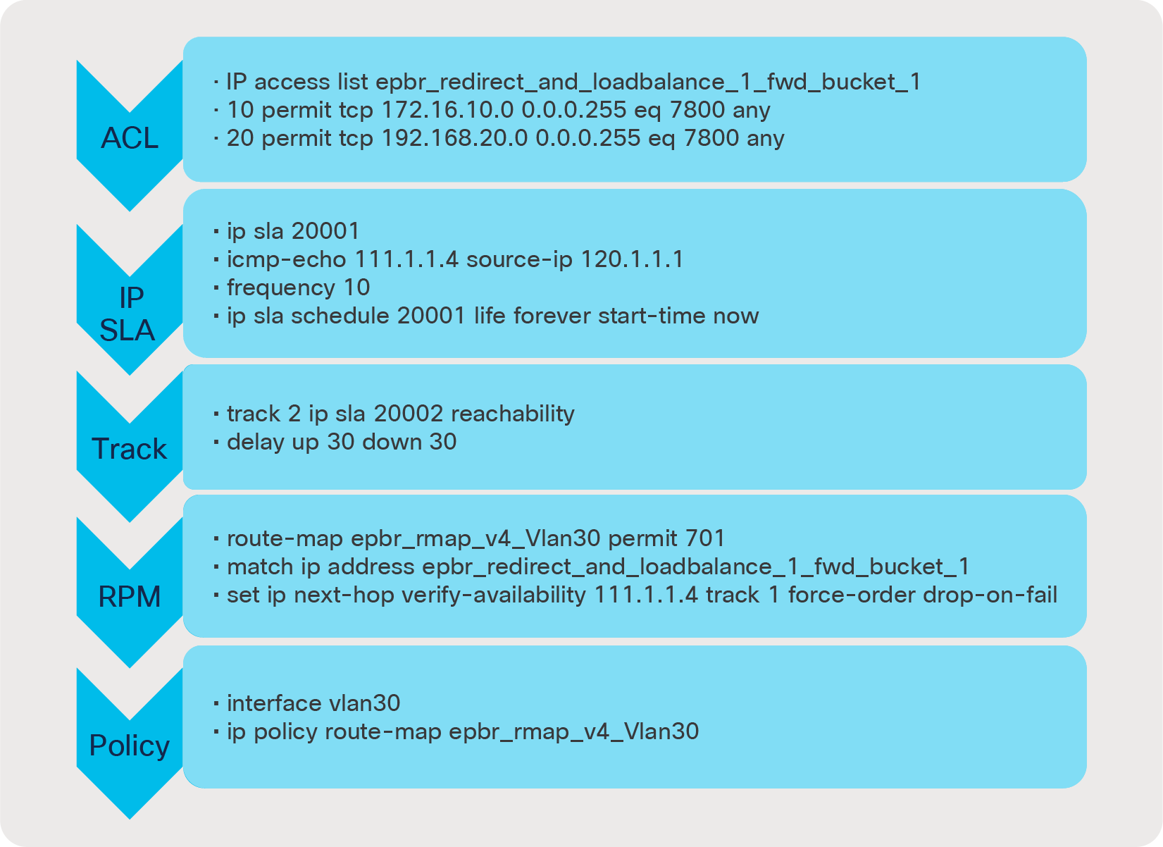
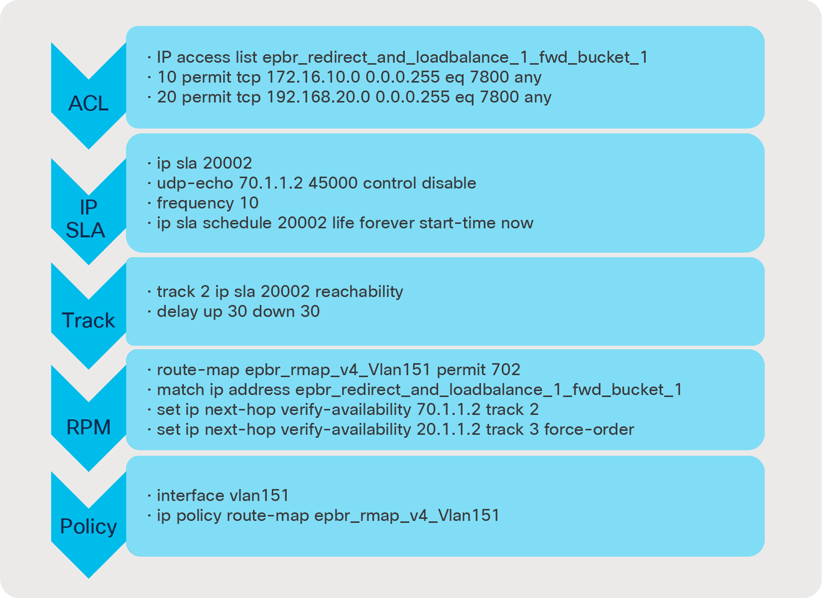
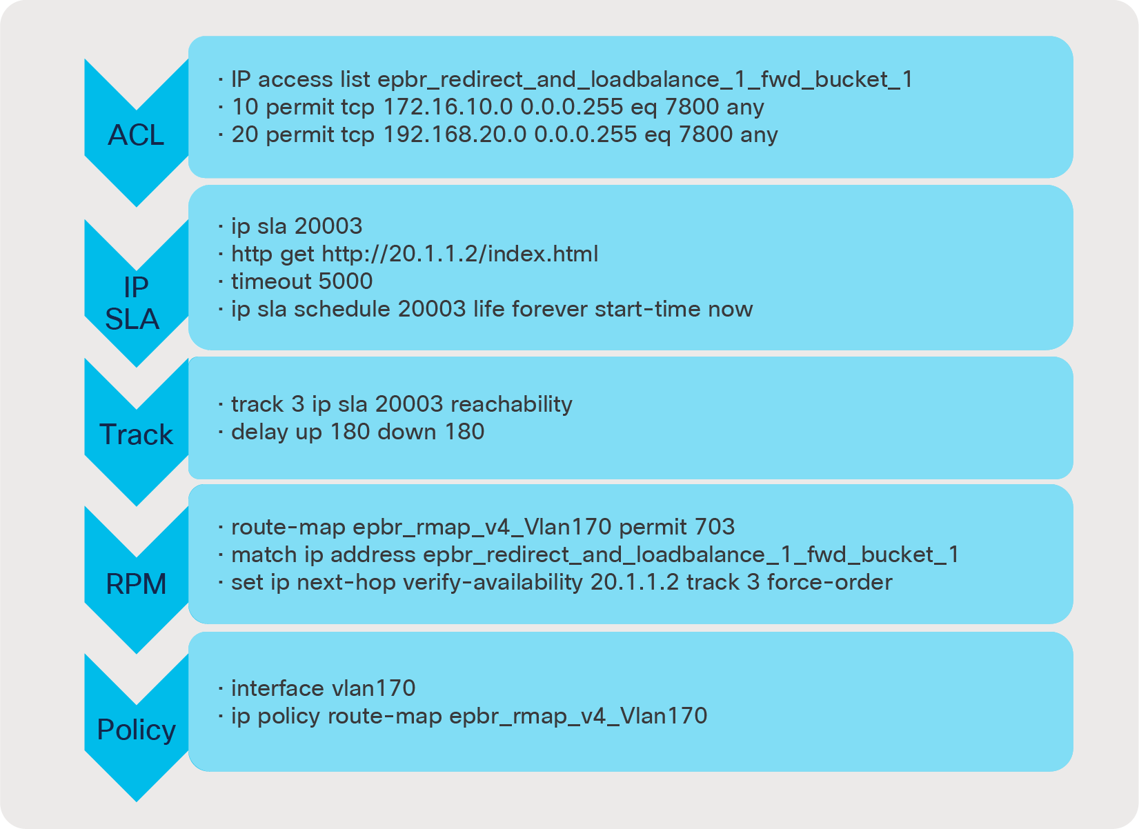
Dynamic configuration snippet generated for forward chain with match ACL “app1”
The configuration below gives a preview of how the ACLs, IP SLAs, tracks, route-maps, and PBR policies are autogenerated on a policy application; This in turn helps in traversing the chain from FWÒIPSÒProxy.
1st Element in chain Ò corresponds to service firewall with fail-action drop.
2nd Element in chain Ò corresponds to service IPS with fail-action bypass.
3rd Element in chain Ò corresponds to service Proxy with fail-action forward
Similarly, on applying the reverse policy the reverse ACLs and route-map configurations are auto-generated by ePBR. ePBR also reverses the order in which return traffic traverses the chain.
ePBR policy runtime state verification using show command:
switch# show epbr policy redirect_and_loadbalance !! indicates forward traffic flow
Policy-map : redirect_and_loadbalance
Match clause:
ip address (access-lists): app1
Service chain:
service firewall, sequence 10, fail-action Drop
IP 111.1.1.4 track 1 [UP]
service ips, sequence 20, fail-action Bypass
IP 70.1.1.2 track 2 [UP]
service proxy, sequence 30, fail-action forward
IP 20.1.1.2 track 3 [UP]
Match clause:
ip address (access-lists): app2
Service chain:
service caching_servers, sequence 10, fail-action No fail-action
IP 110.1.1.2 track 4 [UP]
IP 110.1.1.3 track 5 [UP]
Policy Interfaces:
Vlan30
switch# show epbr policy redirect_and_loadbalance reverse !! indicates reverse traffic flow
Policy-map : redirect_and_loadbalance
Match clause:
ip address (access-lists): app1
Service chain:
service proxy, sequence 30, fail-action forward
IP 20.1.1.3 track 8 [UP]
service ips, sequence 20, fail-action Bypass
IP 170.1.1.2 track 7 [UP]
service firewall, sequence 10, fail-action Drop
IP 151.1.1.4 track 6 [UP]
Match clause:
ip address (access-lists): app2
Service chain:
service caching_servers, sequence 10, fail-action No fail-action
IP 150.1.1.2 track 9 [UP]
IP 150.1.1.3 track 10 [UP]
Policy Interfaces:
Vlan40
ePBR policy statistics and traffic count verification using show commands :
switch# show epbr statistics policy redirect_and_loadbalance
Policy-map redirect_and_loadbalance, match app1
Bucket count: 1
traffic match : epbr_redirect_and_loadbalance_1_fwd_bucket_1
firewall : 10
ips : 10
proxy : 10
Policy-map redirect_and_loadbalance, match app2
Bucket count: 8
traffic match : epbr_redirect_and_loadbalance_2_fwd_bucket_1
caching_servers : 5
traffic match : epbr_redirect_and_loadbalance_2_fwd_bucket_2
caching_servers : 5
traffic match : epbr_redirect_and_loadbalance_2_fwd_bucket_3
caching_servers : 5
traffic match : epbr_redirect_and_loadbalance_2_fwd_bucket_4
caching_servers : 5
traffic match : epbr_redirect_and_loadbalance_2_fwd_bucket_5
caching_servers : 5
traffic match : epbr_redirect_and_loadbalance_2_fwd_bucket_6
caching_servers : 5
traffic match : epbr_redirect_and_loadbalance_2_fwd_bucket_7
caching_servers : 5
traffic match : epbr_redirect_and_loadbalance_2_fwd_bucket_8
caching_servers : 5
switch# show epbr statistics policy redirect_and_loadbalance reverse
Policy-map redirect_and_loadbalance, match app1
Bucket count: 1
traffic match : epbr_redirect_and_loadbalance_1_rev_bucket_1
proxy : 10
ips : 10
firewall : 10
Policy-map redirect_and_loadbalance, match app2
Bucket count: 8
traffic match : epbr_redirect_and_loadbalance_2_rev_bucket_1
caching_servers : 5
traffic match : epbr_redirect_and_loadbalance_2_rev_bucket_2
caching_servers : 5
traffic match : epbr_redirect_and_loadbalance_2_rev_bucket_3
caching_servers : 5
traffic match : epbr_redirect_and_loadbalance_2_rev_bucket_4
caching_servers : 5
traffic match : epbr_redirect_and_loadbalance_2_rev_bucket_5
caching_servers : 5
traffic match : epbr_redirect_and_loadbalance_2_rev_bucket_6
caching_servers : 5
traffic match : epbr_redirect_and_loadbalance_2_rev_bucket_7
caching_servers : 5
traffic match : epbr_redirect_and_loadbalance_2_rev_bucket_8
caching_servers : 5
Use case 2: Selective traffic redirection across active/standby service appliances
In order to increase network reliability, provisioning two identical service appliances as a high-availability pair in active/standby fashion is a common deployment mode. In this use case, traffic from clients is selectively filtered based on match criteria and redirected to the firewall and load-balancer chain, before being sent to the server. ePBR intelligently tracks which node in each cluster is active and automatically redirects the traffic to the new active node in case the original active node fails.
Use case 2 deployment example:
In this example, we are using a two-tiered VXLAN EVPN spine-and-leaf network deployment.
The forward and reverse traffic flow from and to clients is always redirected to the active firewall and then to the active load-balancer. The solution automatically takes care of detecting which service node is active, so no additional configuration is necessary. Note that in Figure 6:
● BL is a border leaf or edge device
● L1 and L2 are server leaf switches hosting servers A and B
● SL A1, SL A2, SL B1, and SL B2 are VPC service-leaf switches hosting the firewall and load-balancer appliances in active/standby fashion.
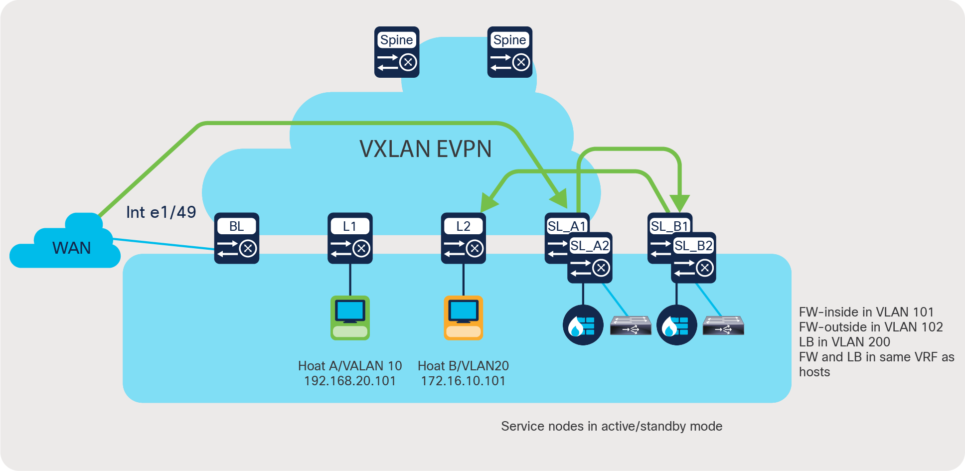
Use case 2: Selective traffic redirection across active/standby service appliances
Here is a brief description of the intent of the use case depicted in Figure 6:
● Firewall is a dual-arm appliance, and the load balancer is a single-arm appliance.
● Traffic enters the border leaf on interface e1/49 from WAN.
● We need selective segregation of the traffic based on two match criteria, namely:
◦ Custom application (which uses destination port 7800)
◦ Web-based application (which uses destination port 80)
● Custom-application-based traffic needs to be redirected to the active firewall followed by the active load-balancer before going to the server.
● Web-application-based traffic needs to reach the firewall only and before being processed by the server.
● All other traffic uses routing table rules.
● The following fail-action rules need to be applied in the service-chain:
◦ If LB is down, bypass the load-balancer.
◦ If FW is down, drop the traffic.
● Symmetry must be maintained for return traffic.
Configuration on service leaves:
Step 1: Onboard appliances
epbr service firewall
vrf tenant_a
service-end-point ip 10.1.1.2 interface Vlan10
probe icmp frequency 4 timeout 2 source-interface loopback9
reverse ip 50.1.1.2 interface Vlan50
probe icmp frequency 4 timeout 2 source-interface loopback10
epbr service load-balancer
service-interface Vlan20
vrf tenant_a
probe http get index.html source-interface loopback9
service-end-point ip 20.1.1.2
reverse ip 20.1.1.2
! reverse ip for the load-balancer is same as the end-point ip as it is a single arm device
Step 2: Create traffic selection rules
ip access-list custom_app
10 permit tcp 172.16.10.0/24 any eq 7800
20 permit tcp 192.168.20.0/24 any eq 7800
ip access-list web
10 permit tcp 172.16.10.0/24 any eq www
20 permit tcp 192.168.20.0/24 any eq www
Step 3: Define ePBR traffic redirect policy
epbr policy service_chain
statistics
match ip address custom_app
load-balance buckets 4 method src-ip
10 set service firewall fail-action drop
20 set service load-balancer fail-action bypass
match ip address web
load-balance buckets 2 method src-ip
10 set service firewall fail-action drop
Step 4: Apply the ePBR Policy on L3vni interfaces for forward and return traffic
interface Vlan100
! L3 VNI SVI
vrf member tenant_a
ip forward
ipv6 forward
epbr ip policy service_chain
epbr ip policy service_chain reverse
Configuration on leaves hosting the servers:
Step 1,Step 2 and Step 3 are similar to configuring a service leaf
Step 4: Apply the ePBR Policy on relevant anycast gateway interfaces for return traffic from the servers to be redirected back to the WAN maintaining the symmetry
Interface Vlan10
vrf member tenant_a
fabric forwarding mode anycast gateway
epbr ip policy service_chain reverse
Configuration on border leaf:
Step 1: Onboard appliances – The end point definition need not necessarily have the SVI definition along if the endpoint is not local
pbr service firewall
vrf tenant_a
service-end-point ip 10.1.1.2
probe icmp frequency 4 timeout 2 source-interface loopback9
reverse ip 50.1.1.2
probe icmp frequency 4 timeout 2 source-interface loopback10
epbr service load-balancer
vrf tenant_a
probe http get index.html source-interface loopback9
service-end-point ip 20.1.1.2
reverse ip 20.1.1.2
Step 2: Create traffic selection rules
ip access-list custom_app
10 permit tcp 172.16.10.0/24 any eq 7800
20 permit tcp 192.168.20.0/24 any eq 7800
ip access-list web
10 permit tcp 172.16.10.0/24 any eq www
20 permit tcp 192.168.20.0/24 any eq www
Step 3: Define EPBR traffic redirect policy
epbr policy service_chain
statistics
match ip address custom_app
load-balance buckets 4 method src-ip
10 set service firewall fail-action drop
20 set service load-balancer fail-action bypass
match ip address web
load-balance buckets 2 method src-ip
10 set service firewall fail-action drop
Step 4: Apply the ePBR Policy on external interface connecting to the WAN
interface e1/49
! Interface facing the WAN
vrf member tenant_a
epbr ip policy service_chain
Note: In this case traffic hitting the border leaf is the forward traffic which needs to be redirected to the firewall before being processed by the servers. Hence only forward policy is applied here
ePBR policy runtime state verification using show commands:
show epbr policy service_chain
Policy-map : service_chain
Match clause:
ip address (access-lists): custom_app
Service chain:
service firewall, sequence 10, fail-action Drop
IP 10.1.1.2 track 1 [UP]
service load-balancer, sequence 20, fail-action Bypass
IP 20.1.1.2 track 2 [UP]
Match clause:
ip address (access-lists): web
Service chain:
service firewall, sequence 10, fail-action Drop
IP 10.1.1.2 track 1 [UP]
Policy Interfaces:
Eth1/49
Note: Use reverse keyword in show command to view reverse service chain
show epbr statistics policy service_chain
Policy-map service_chain, match custom_app
Bucket count: 4
traffic match : epbr_service_chain_1_fwd_bucket_1
firewall : 10
load-balancer : 0
traffic match : epbr_service_chain_1_fwd_bucket_2
firewall : 10
load-balancer : 0
traffic match : epbr_service_chain_1_fwd_bucket_3
firewall : 10
load-balancer : 0
traffic match : epbr_service_chain_1_fwd_bucket_4
firewall : 10
load-balancer : 0
Policy-map service_chain, match web
Bucket count: 2
traffic match : epbr_service_chain_2_fwd_bucket_1
firewall : 10
traffic match : epbr_service_chain_2_fwd_bucket_2
firewall : 10
Use case 3: Service chaining and load balancing in 5G deployments
Due to the exponential growth for wireless services over the years, the mobile packet core has one of the most demanding packet processing workloads. Mobile network operators have the need to classify traffic flows and redirect them as necessary to specific service nodes in order to meet certain security and optimization requirements.
ePBR service chaining and load-balancing capability together enable mobile network operators to flexibly insert and scale various network services in mobile packet core in order to deliver a high-quality and secure data-service experience for subscribers. ePBR can load balance across different service endpoints, enabling operators to horizontally scale their network.
Use case 3 deployment example:
The example below shows how traffic inside a mobile packet core can be load balanced first across a cluster of TCP optimizers and then service chained to firewall/IPS and CG-NAT devices, using ePBR. ePBR ensures that symmetry is maintained for a given flow by making sure that traffic in both forward and reverse direction is redirected to the same service endpoint in the cluster of TCP optimizers.
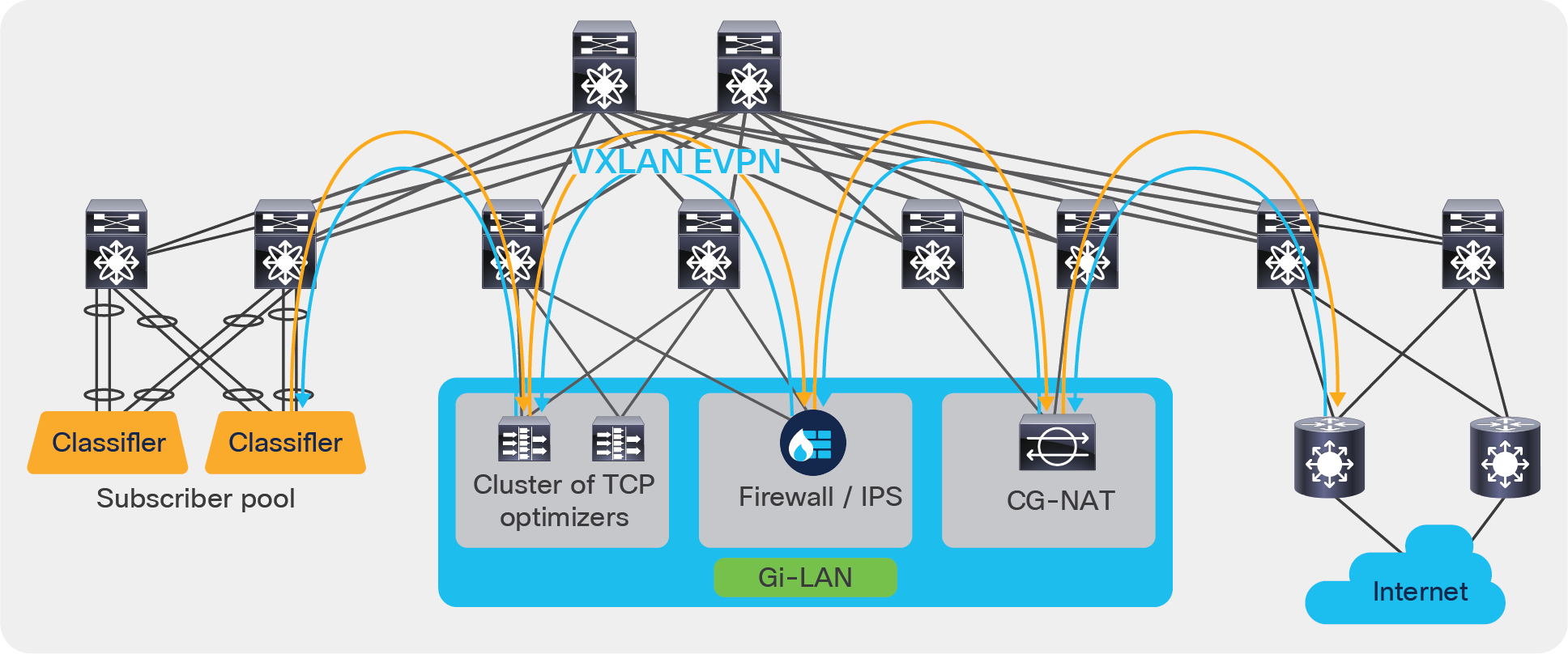
Use case 3: Service chaining and load balancing in 5G deployments
Configuration on service leaves:
Step 1: Onboard the appliances
epbr service firewall
vrf tenant_a
service-end-point ip 111.1.1.4 interface Vlan111
probe icmp source-interface loopback0
reverse ip 151.1.1.4 interface Vlan151
probe icmp source-interface loopback1
epbr service cg_nat
vrf tenant_a
service-interface Vlan20
probe http get index.html
service-end-point ip 20.1.1.2
reverse ip 20.1.1.3
epbr service tcp_optimizers
vrf tenant_a
! traffic will be load-balanced between the optimizers
! optimizer1
service-end-point ip 110.1.1.2 interface Vlan110
probe icmp source-interface loopback0
reverse ip 150.1.1.2 interface Vlan150
probe icmp source-interface loopback1
! optimizer2
service-end-point ip 110.1.1.3 interface Vlan110
probe icmp source-interface loopback0
reverse ip 150.1.1.3 interface Vlan150
probe icmp source-interface loopback1
Step 2: Create traffic selection rules
ip access-list web
10 permit tcp 172.16.10.0/24 any eq www
20 permit tcp 192.168.20.0/24 any eq www
IP access list exclude_traffic
10 permit tcp 172.16.10.10/32 any
20 permit tcp 172.16.10.11/32 any
Step 3: Define ePBR traffic redirect policy
In the policy defined below, Traffic destined to web based application(filtered thru ‘web’ ACL), will be service chained. Additionally we exclude certain traffic flows from the service chain (filtered by ‘exclude_traffic’ ACL). On the event of TCP_optimizer cluster failure, the traffic is bypassed and is forwarded to the next element in chain. On the event of firewall or CG_NAT service node failure, traffic is dropped.
epbr policy servicechain_and_loadbalance
statistics
match ip address exclude_traffic exclude
match ip address web
! TCP optimizerÒfirewallÒcg_nat chain
10 set service tcp_optimizers fail-action bypass
20 set service firewall fail-action drop
30 set service cg_nat fail-action drop
Step 4: Apply the ePBR Policy on ingress interface connecting to the classifier for forward traffic and apply policy with reverse keyword on egress interfaces connecting to the internet
interface Vlan30
!forward policy applied to ingress interface facing classifier
no shutdown
ip address 30.1.1.1/24
ipv6 address 2030::1/24
vrf member tenant_a
epbr ip policy servicechain_and_loadbalance
interface Vlan40
! Reverse policy applied to egress interface facing WAN for reverse flow
no shutdown
vrf member tenant_a
ip address 40.1.1.1/24
ipv6 address 2040::1/24
epbr ip policy servicechain_and_loadbalance reverse
interface vlan100
! L3vni interface on service leafs
ip forward
no ip redirect
vrf member tenant_a
epbr ip policy servicechain_and_loadbalance
epbr ip policy servicechain_and_loadbalance reverse
ePBR policy runtime state verification using show commands:
show epbr policy servicechain_and_loadbalance
Policy-map : servicechain_and_loadbalance
Match clause:
ip address (access-lists): exclude_traffic
action:Deny
Match clause:
ip address (access-lists): web
action:Redirect
service tcp_optimizers, sequence 10, fail-action Bypass
IP 110.1.1.2 track 1 [UP]
IP 110.1.1.3 track 2 [UP]
service firewall, sequence 20, fail-action Drop
IP 111.1.1.4 track 3 [UP]
service cg_nat, sequence 30, fail-action Drop
IP 20.1.1.2 track 4 [UP]
Policy Interfaces:
Vlan100
show epbr policy servicechain_and_loadbalance reverse
Policy-map : servicechain_and_loadbalance
Match clause:
ip address (access-lists): exclude_traffic
action:Deny
Match clause:
ip address (access-lists): web
action:Redirect
service cg_nat, sequence 30, fail-action Drop
IP 20.1.1.3 track 8 [UP]
service firewall, sequence 20, fail-action Drop
IP 151.1.1.4 track 7 [UP]
service tcp_optimizers, sequence 10, fail-action Bypass
IP 150.1.1.2 track 5 [UP]
IP 150.1.1.3 track 6 [UP]
Policy Interfaces:
Vlan100
Figure 8 illustrates how ePBR can bypass the TCP optimizer on the event of a failure (ePBR detects the failure of a service node, using probes) and redirects the traffic to the next element in the chain, which is a firewall.
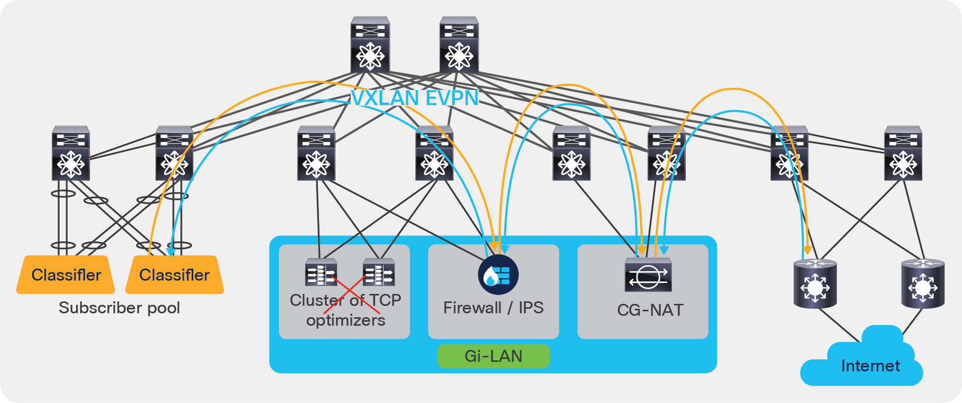
ePBR bypass capability
Use case 4: Load share across a tenant edge firewall cluster
When integrating a Layer-3 firewall in a VXLAN EVPN fabric with a distributed anycast gateway, each of these zones must correspond to a VRF/tenant on the fabric. The traffic within a tenant is routed by the fabric. Traffic between the tenants is routed by a firewall. This scenario is often referred to as a tenant edge firewall. BGP or static route is typically used to peer between the firewall and the service leaf.
In a massively scaled data-center fabric, firewalls are becoming a bottleneck, and firewall clusters are provisioned to help alleviate this problem. ePBR can be leveraged to load share between the service nodes in the tenant edge firewall cluster. ePBR also helps in maintaining symmetry between forward and reverse traffic, thus supporting the stateful nature of the firewall.
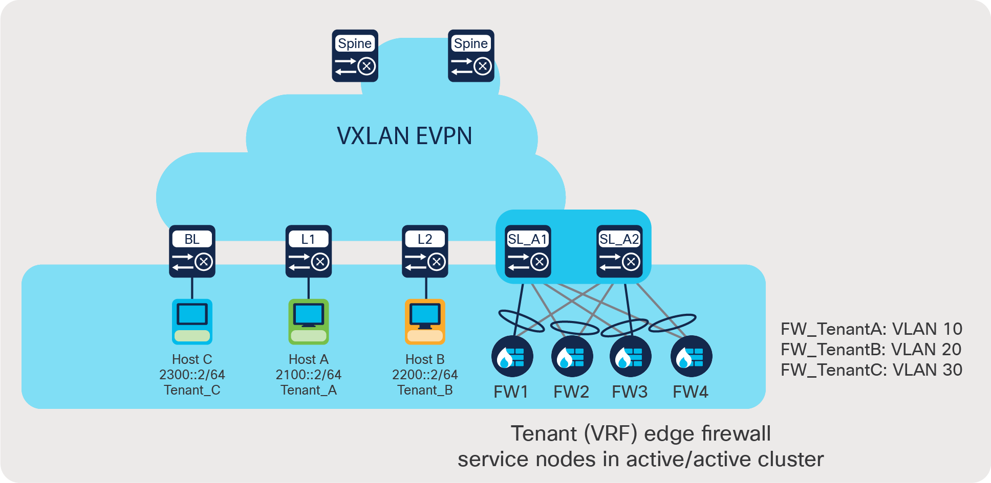
Use case 4: Load share across a tenant edge firewall cluster
Use case 4 deployment example:
● Traffic between different VRFs A, B, and C must be inspected by the tenant edge firewall.
● Forward and reverse traffic must land on the same firewall to maintain symmetry.
Step 1: Onboard appliances
• The order in which Firewall ip address are listed under each service should follow same order – FW1,FW2,FW3,FW4 . This will in turn ensure traffic in the forward and return direction hits the same firewall
• This below configuration is required only on the service leaf
epbr service FW_cluster_A
service-interface Vlan10
vrf Tenant_A
probe icmp frequency 4 retry-down-count 1 retry-up-count 1 timeout 2 source-interface loopback10
service-end-point ipv6 2010::2
service-end-point ipv6 2010::3
service-end-point ipv6 2010::4
service-end-point ipv6 2010::5
epbr service FW_cluster_B
service-interface Vlan20
vrf Tenant_B
probe icmp frequency 4 retry-down-count 1 retry-up-count 1 timeout 2 source-interface loopback20
service-end-point ipv6 2020::2
service-end-point ipv6 2020::3
service-end-point ipv6 2020::4
service-end-point ipv6 2020::5
epbr service FW_cluster_C
service-interface Vlan30
vrf Tenant_C
probe icmp frequency 4 retry-down-count 1 retry-up-count 1 timeout 2 source-interface loopback30
service-end-point ipv6 2030::2
service-end-point ipv6 2030::3
service-end-point ipv6 2030::4
service-end-point ipv6 2030::5
Step 2: Create traffic selection rules
IPv6 access list AtoB
10 permit ipv6 2100::2/64 2200::2/64
IPv6 access list AtoC
10 permit ipv6 2100::2/64 2300::2/64
IPv6 access list BtoA
10 permit ipv6 2200::2/64 2100::2/64
IPv6 access list BtoC
10 permit ipv6 2200::2/64 2300::2/64
IPv6 access list CtoA
10 permit ipv6 2300::2/64 2100::2/64
IPv6 access list CtoB
10 permit ipv6 2300::2/64 2200::2/64
Step 3: Define ePBR traffic redirect policy
• For forward traffic if source based load-balancing is chosen, return traffic must use destination based load-balancing as shown in example below
epbr policy Tenant_A
match ipv6 address AtoB
load-balance buckets 4 method src-ip
10 set service FW_cluster_A
match ipv6 address AtoC
load-balance buckets 4 method src-ip
10 set service FW_cluster_A
epbr policy Tenant_B
match ipv6 address BtoA
load-balance buckets 4 method dst-ip
10 set service FW_cluster_B
match ipv6 address BtoC
load-balance buckets 4 method src-ip
10 set service FW_cluster_B
epbr policy Tenant_C
match ipv6 address CtoA
load-balance buckets 4 method dst-ip
10 set service FW_cluster_C
match ipv6 address CtoB
load-balance buckets 4 method dst-ip
10 set service FW_cluster_C
Step 4: Apply the ePBR Policy on L3vni interfaces for forward and return traffic on respective VRFs
Note: If there are servers on same leaf, the policy needs to be applied on the Tenant SVI as well
interface Vlan110
no shutdown
vrf member Tenant_A
ip forward
ipv6 forward
epbr ipv6 policy Tenant_A
interface Vlan120
no shutdown
vrf member Tenant_B
ip forward
ipv6 forward
epbr ipv6 policy Tenant_B
interface Vlan130
no shutdown
vrf member Tenant_C
ip forward
ipv6 forward
epbr ipv6 policy Tenant_C
ePBR policy runtime state verification using show commands:
show epbr policy Tenant_A
Policy-map : Tenant_A
Match clause:
ipv6 address (access-lists): AtoB
Service chain:
service FW_cluster_A, sequence 10, fail-action No fail-action
IPV6 2010::2 track 1 [UP]
IPV6 2010::3 track 2 [UP]
IPV6 2010::4 track 3 [UP]
IPV6 2010::5 track 4 [UP]
Match clause:
ipv6 address (access-lists): AtoC
Service chain:
service FW_cluster_A, sequence 10, fail-action No fail-action
IPV6 2010::2 track 1 [UP]
IPV6 2010::3 track 2 [UP]
IPV6 2010::4 track 3 [UP]
IPV6 2010::5 track 4 [UP]
Policy Interfaces:
Vlan110
show epbr policy Tenant_B
Policy-map : Tenant_B
Match clause:
ipv6 address (access-lists): BtoA
Service chain:
service FW_cluster_B, sequence 10, fail-action No fail-action
IPV6 2020::2 track 5 [UP]
IPV6 2020::3 track 6 [UP]
IPV6 2020::4 track 7 [UP]
IPV6 2020::5 track 8 [UP]
Match clause:
ipv6 address (access-lists): BtoC
Service chain:
service FW_cluster_B, sequence 10, fail-action No fail-action
IPV6 2020::2 track 5 [UP]
IPV6 2020::3 track 6 [UP]
IPV6 2020::4 track 7 [UP]
IPV6 2020::5 track 8 [UP]
Policy Interfaces:
Vlan120
show epbr policy Tenant_C
Policy-map : Tenant_C
Match clause:
ipv6 address (access-lists): CtoA
Service chain:
service FW_cluster_C, sequence 10, fail-action No fail-action
IPV6 2030::2 track 10 [UP]
IPV6 2030::3 track 11 [UP]
IPV6 2030::4 track 12 [UP]
IPV6 2030::5 track 13 [UP]
Match clause:
ipv6 address (access-lists): CtoB
Service chain:
service FW_cluster_C, sequence 10, fail-action No fail-action
IPV6 2030::2 track 10 [UP]
IPV6 2030::3 track 11 [UP]
IPV6 2030::4 track 12 [UP]
IPV6 2030::5 track 13 [UP]
Policy Interfaces:
Vlan130
ePBR leverages PBR (policy-based routing) to redirect traffic and hence uses “Ingress RACL” space in TCAM. Here is a brief explanation of the logic regarding how TCAM is calculated:
● Each match entry in ACL uses one TCAM entry.
● If the same policy is applied on multiple interfaces within a VRF, the TCAM is shared.
● When load balancing is enabled, the TCAM allocation is a multiplier of the number of ACEs used with the number of buckets specified in the policy.
Example: If eight buckets are configured, TCAM usage = 8x No. of ACEs in the match ACL.
● If both forward and reverse ePBR policies are enabled, twice the resources should be accounted and accordingly allocated.
switch# show hardware access-list resource utilization | I RACL
ACL Hardware Resource Utilization (Mod 1)
---------------------------------------------------------------------------
Used Free Percent
Utilization
---------------------------------------------------------------------------
Ingress RACL 2 1790 0.11
Ingress RACL IPv4 0 0.00
Ingress RACL IPv6 0 0.00
Ingress RACL MAC 0 0.00
Ingress RACL ALL 2 0.11
Ingress RACL OTHER 0 0.00
Egress RACL 2 1790 0.11
Egress RACL IPv4 0 0.00
Egress RACL IPv6 0 0.00
Egress RACL MAC 0 0.00
Egress RACL ALL 2 0.11
Egress RACL OTHER 0 0.00
Ingress RACL 2 1790 0.11
Ingress RACL IPv4 0 0.00
Ingress RACL IPv6 0 0.00
Ingress RACL MAC 0 0.00
Ingress RACL ALL 2 0.11
Ingress RACL OTHER 0 0.00
Egress RACL 2 1790 0.11
Egress RACL IPv4 0 0.00
Egress RACL IPv6 0 0.00
Egress RACL MAC 0 0.00
Egress RACL ALL 2 0.11
Egress RACL OTHER 0 0.00
● It is recommended to not share the same traffic selection ACL and overlapping subnets across multiple match statements in the ePBR configuration.
● On the event of service or entire appliance cluster failure, symmetry in traffic can be achieved by using a fail-action bypass.
● For enabling health monitoring and probes in the fabric deployment, loopback interfaces must be configured as source interfaces in service endpoints.
● There can be only one drop and/or exclude ACL match statement per policy.
● In a VXLAN fabric, an active/standby chain with three or more service nodes in the chain requires that no two nodes of different types can be behind the same service leaf.
The Cisco Nexus 9000 Series Switches with ePBR enables users to optimize their data center by providing them simplified workflows to onboard service nodes and redirect traffic to them. The solution allows users to horizontally scale their service node deployment, ensuring that the network is never a bottleneck. This not only ensures application performance is optimal, but also ensures the network complies with security requirements. ePBR is an innovative solution and caters to the emerging needs of service chaining in modern data-center networks.
Additional documentation and related topics can be found at the sites listed below.
ePBR configuration guide: https://www.cisco.com/c/en/us/td/docs/dcn/nx-os/nexus9000/101x/configuration/epbr/cisco-nexus-9000-series-nx-os-epbr-configuration-guide-101x/m-configuring-epbr.html.
Table 2 from the link below provides ePBR verified scale numbers: https://www.cisco.com/c/en/us/td/docs/switches/datacenter/nexus9000/sw/93x/scalability/guide-936/cisco-nexus-9000-series-nx-os-verified-scalability-guide-936.html.
ePBR NX-API REST API reference and user guide: https://developer.cisco.com/docs/cisco-nexus-3000-and-9000-series-nx-api-rest-sdk-user-guide-and-api-reference-release-9-3x/#!configuring-epbr/configuring-epbr.
VXLAN EVPN deployment and configuration information: https://www.cisco.com/c/en/us/td/docs/switches/datacenter/nexus9000/sw/93x/vxlan/configuration/guide/b-cisco-nexus-9000-series-nx-os-vxlan-configuration-guide-93x.html.
L4 to L7 service integration and deployment using DCNM: https://www.cisco.com/c/en/us/td/docs/switches/datacenter/sw/11_4_1/config_guide/lanfabric/b_dcnm_fabric_lan/layer4_layer7_service.html.