NextGen DCI with VXLAN EVPN Multi-Site Using vPC Border Gateways White Paper
Available Languages
Bias-Free Language
The documentation set for this product strives to use bias-free language. For the purposes of this documentation set, bias-free is defined as language that does not imply discrimination based on age, disability, gender, racial identity, ethnic identity, sexual orientation, socioeconomic status, and intersectionality. Exceptions may be present in the documentation due to language that is hardcoded in the user interfaces of the product software, language used based on RFP documentation, or language that is used by a referenced third-party product. Learn more about how Cisco is using Inclusive Language.
This document describes the functionalities and use cases of the vPC Border Gateway (vPC BGW) that is part of the VXLAN EVPN Multi-Site architecture. One of the main objectives of the use cases is to introduce VXLAN EVPN Multi-Site as Data Center Interconnect (DCI) for Classic Ethernet networks. The deployment of vPC BGWs is supported starting with Cisco NX-OS 9.2(1).
The document is structured to provide first an overview of specific use cases that EVPN Multi-Site vPC BGW enables, followed by a detailed walkthrough of EVPN Multi-Site with vPC BGWs used for interconnecting Data Centers built with legacy technology (the DCI use case). The main architectural benefits of such a solution are highlighted, as well as how to eventually migrate those legacy networks to modern VXLAN BGP EVPN fabrics.
A more detailed view of the technology behind vPC BGWs paired with specific design considerations for its deployment is available in the Appendix of this document.
VXLAN EVPN Multi-Site provides an interconnectivity architecture that was first introduced on Cisco Nexus® 9000 series cloud-scale platforms (Cisco Nexus 9000 Series EX, FX and, FX2 platforms) as per Cisco NX-OS 7.0(3)I7(1).
Commonly, a VXLAN EVPN Multi-Site deployment consist of two or more data center networks, usually called “sites” that are interconnected through a VXLAN BGP EVPN Layer 2 and Layer 3 overlay.
EVPN Multi-Site architecture brings back hierarchies to overlay networks introducing external BGP (eBGP) for VXLAN BGP EVPN networks, whereas until now interior BGP (iBGP) was predominant. Following the introduction of eBGP next-hop behavior, Autonomous Systems (ASs) at the Border Gateways (BGWs) were introduced, returning network control points to the overlay network. With this approach, hierarchies are efficiently used to compartmentalize and interconnect multiple overlay networks. Organizations also have a control point to steer and enforce network extension within and beyond a single data center.
VXLAN EVPN Multi-Site architecture is a design for VXLAN BGP EVPN–based overlay networks. It allows interconnection of multiple distinct VXLAN BGP EVPN fabrics or overlay domains, and it allows new approaches to fabric scaling, compartmentalization, and DCI. VXLAN EVPN Multi-Site addresses many use cases, including compartmentalization, hierarchical scale-out approaches, DCI, and the integration of legacy networks; the latter two use cases are the focus of this document.
Network extension across geographically dispersed data centers
EVPN Multi-Site architecture was built with DCI in mind (Figure 1). The overall architecture allows single or multiple fabrics per data center to be positioned and interconnected with single or multiple fabrics in a remote data center. With seamless and controlled Layer 2 and Layer 3 extension via VXLAN BGP EVPN within and between fabrics, the capabilities of VXLAN BGP EVPN itself have been increased. The new functions related to network control, VTEP masking, and BUM traffic enforcement are only some of the features that help make EVPN Multi-Site architecture the most efficient DCI technology.
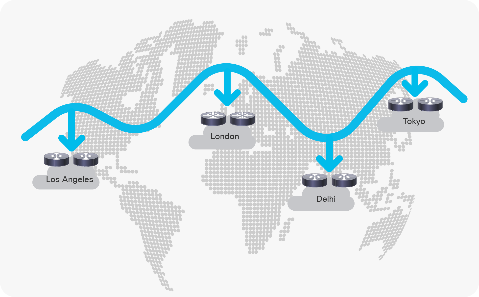
VXLAN EVPN Multi-Site for interconnecting geographically dispersed data centers
Integration with legacy networks
The EVPN Multi-Site solution was not only designed to interconnect VXLAN BGP EVPN data center fabrics but also to facilitate coexistence and migrations scenarios, or to interconnect data center networks built with older (legacy) technologies. In cases where multiple networks with Spanning Tree Protocol (STP), virtual Port Channel (vPC), or Cisco FabricPath exists, EVPN Multi-Site provides state-of-the-art interconnect abilities (Figure 2).
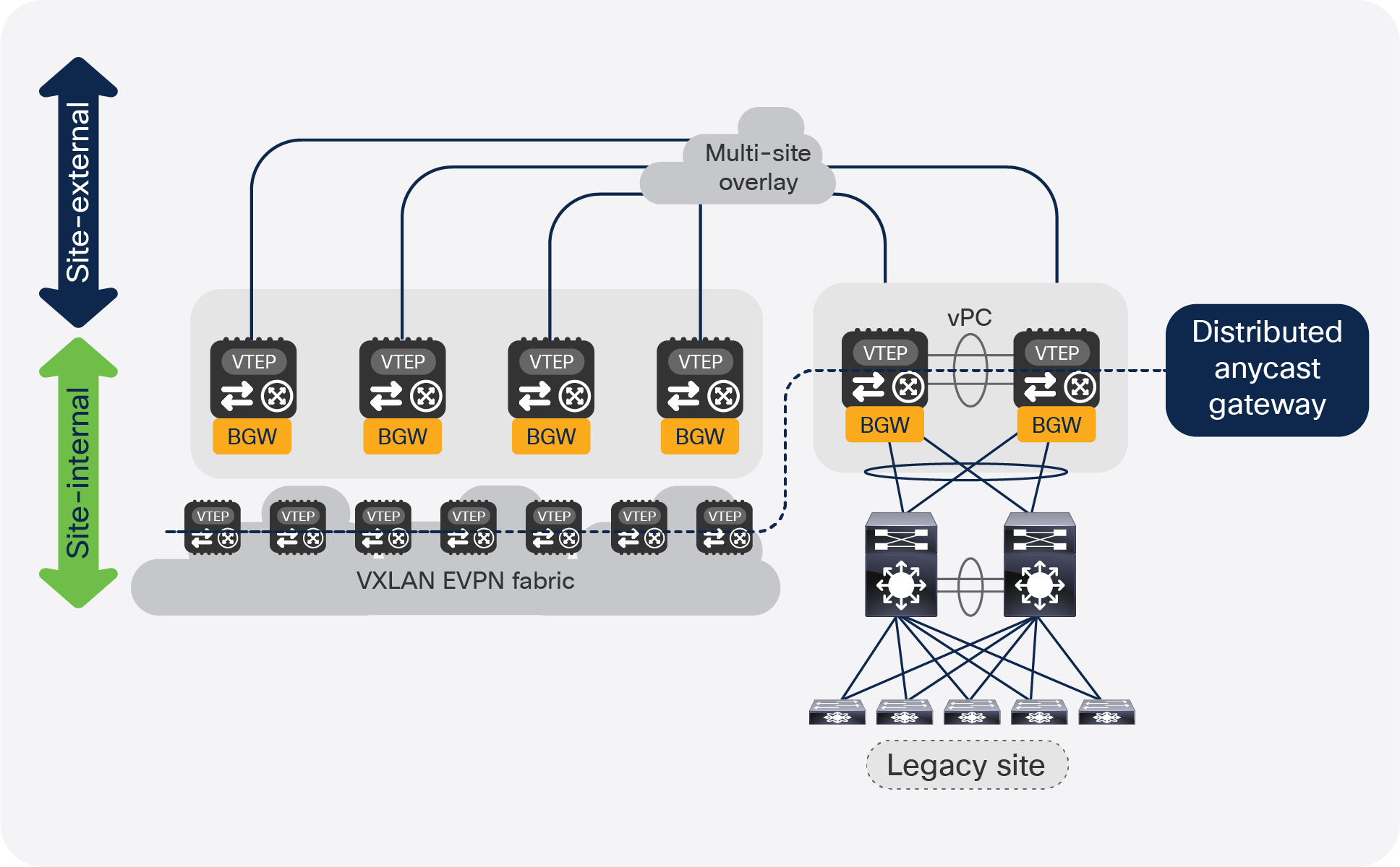
VXLAN EVPN Multi-Site for integrating with legacy networks
VXLAN EVPN Multi-Site architecture is a modern alternative to DCI technologies such as vPC, OTV, VPLS, or EoMPLS, and especially for interconnecting data center networks that are solely built on legacy technologies (for example, STP, vPC, or Cisco FabricPath).
This document focuses on VXLAN EVPN Multi-Site for interconnectivity with legacy networks and for coexistence with VXLAN BGP EVPN fabrics as a modern approach to interconnectivity between data centers.
VXLAN EVPN Multi-Site with vPC BGWs deployment use cases
As previously stated, the deployment of vPC BGW can be introduced for several use cases but was considered the main integration point for legacy networks into an EVPN Multi-Site deployment. The vPC BGW provides redundant Layer 2 attachment through virtual Port-Channel (vPC) and the hosting of the first-hop gateway by using a Distributed Anycast Gateway. With the combination of the EVPN Multi-Site function, the Layer 2 attachment, and the first-hop gateway, the vPC BGW can become an extension of the existing data center networks’ aggregation layer (Figure 3) or it can allow local attachment of endpoints in VXLAN BGP EVPN networks (Figure 4).
vPC BGW attachment
vPC BGW and endpoints
Most commonly, deployments that require the vPC BGW to be attached to the existing legacy network need to either interconnect with a remote network (the DCI use case), or intend a migration to a modern fabric built with VXLAN EVPN technology. In either of the two cases, the coexistence of a VXLAN BGP EVPN fabric with a legacy network has been considered. In these cases, EVPN Multi-Site provides the first-hop gateway function as well as full Layer 2 and Layer 3 connectivity between the various network types. With EVPN Multi-Site and the usage of the Distributed Anycast Gateway (DAG) as the first-hop gateway, host mobility is possible (Figure 5).
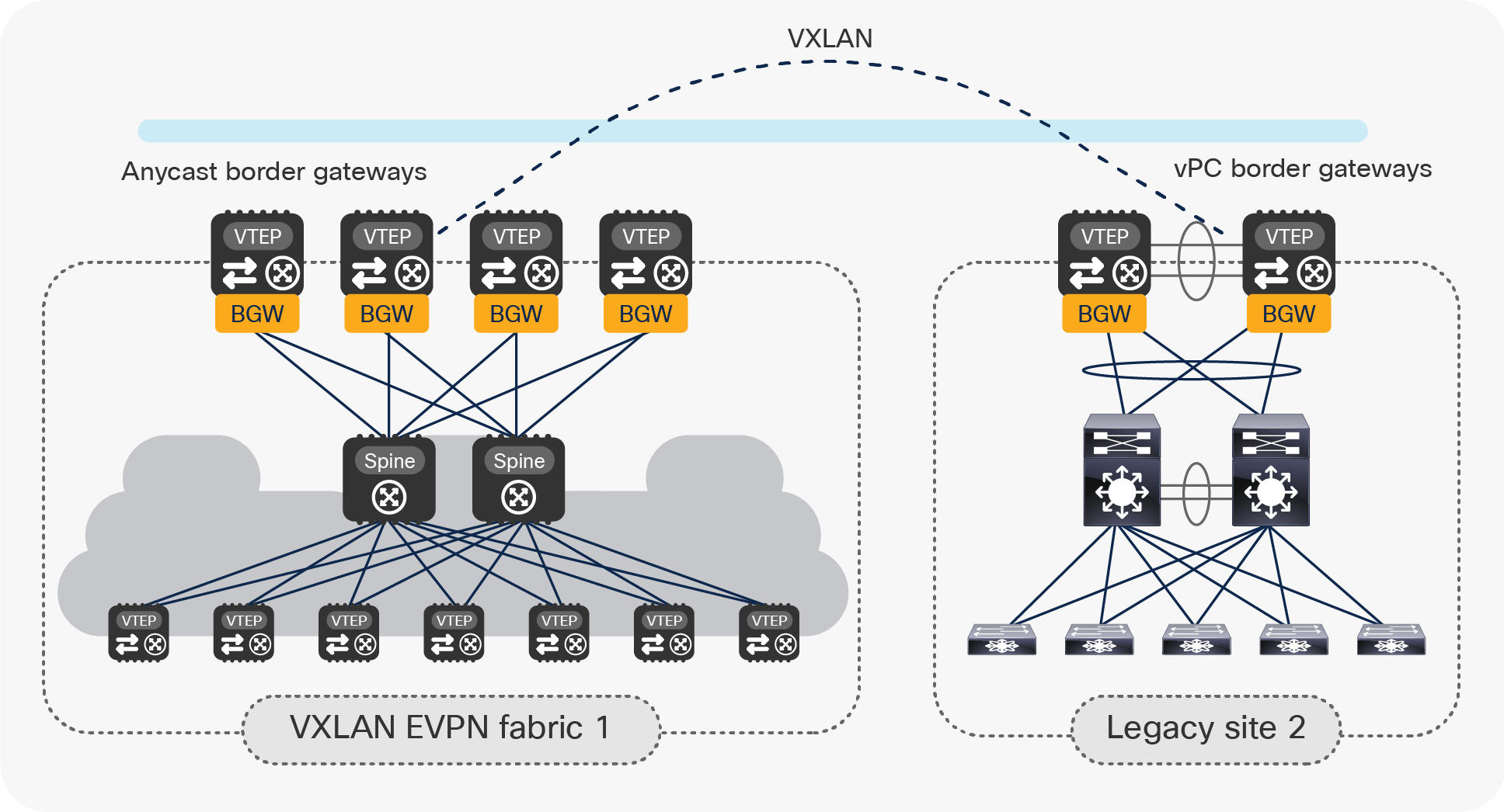
Integration/coexistence of a legacy site with a VXLAN BGP EVPN site with EVPN Multi-Site
vPC BGW nodes to connect multiple legacy data center sites
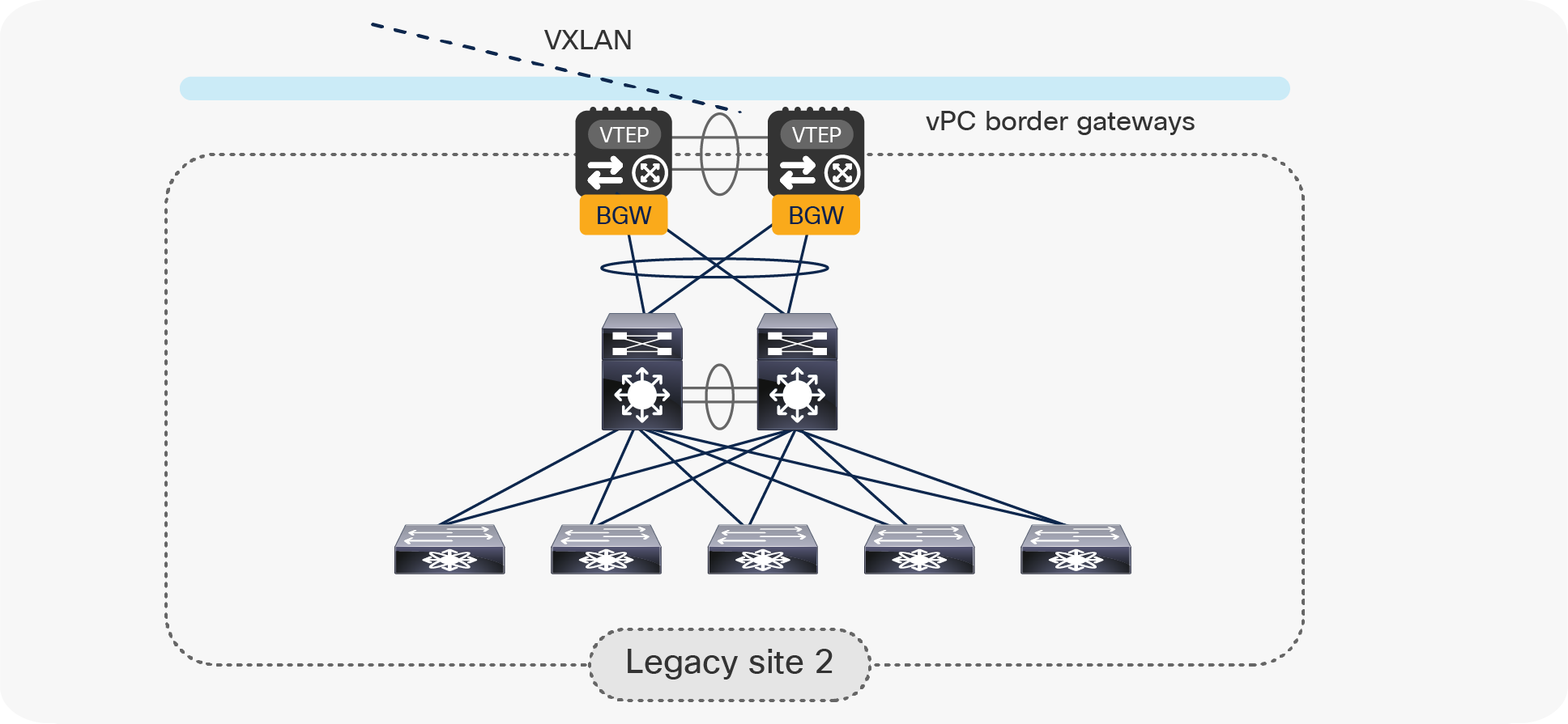
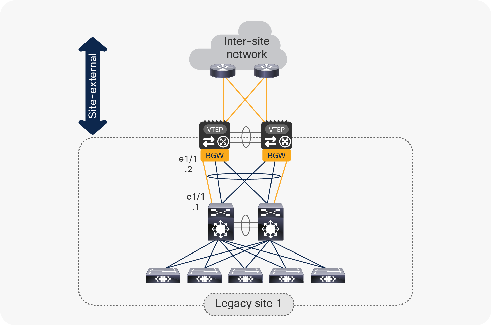
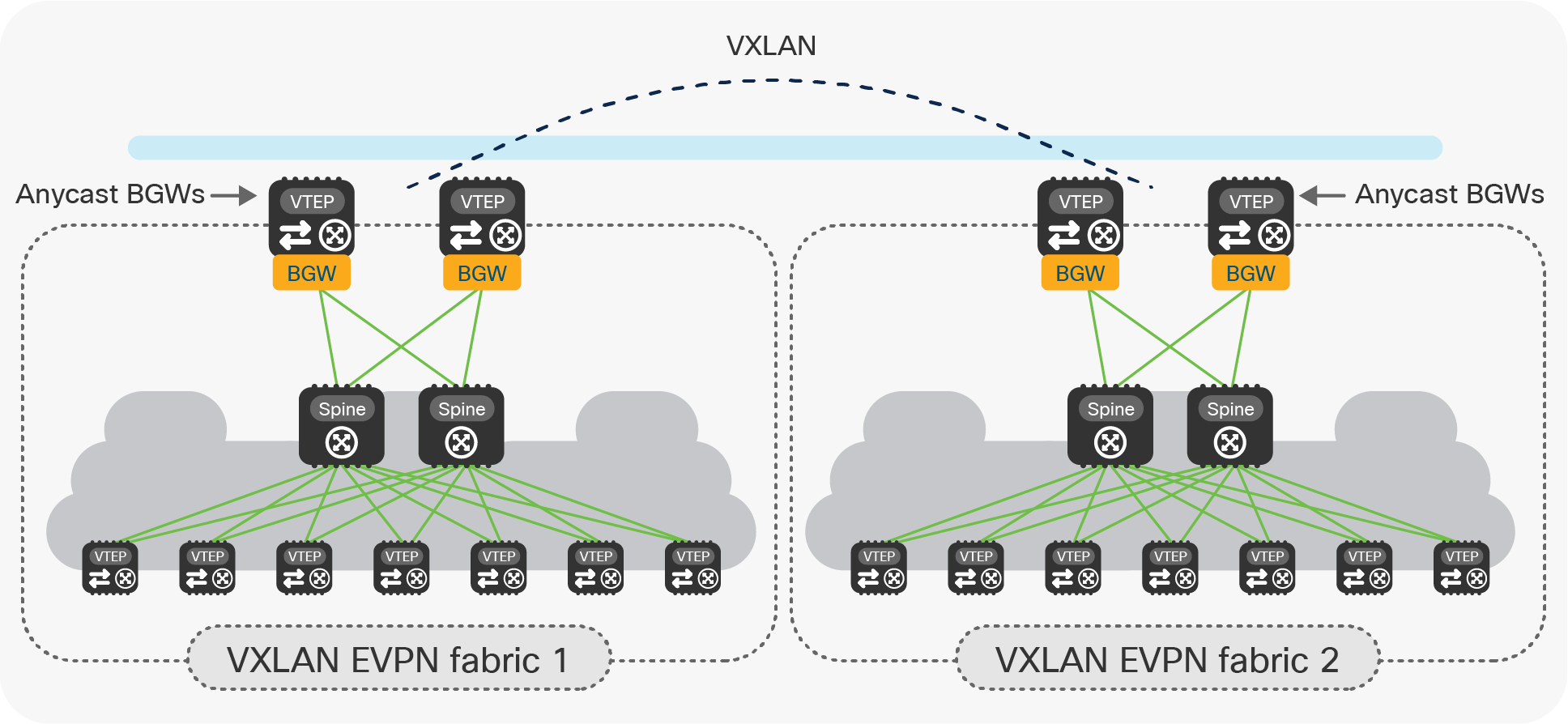
Later in this document, we will discuss in great detail what are the design considerations and configuration best-practices to locally interconnect the pair of vPC BGW nodes to the legacy network. By mirroring this approach, the same deployment model can be adopted to interconnect data center sites that do not leverage VXLAN BGP EVPN as the technology for intrasite connectivity (Figure 6).
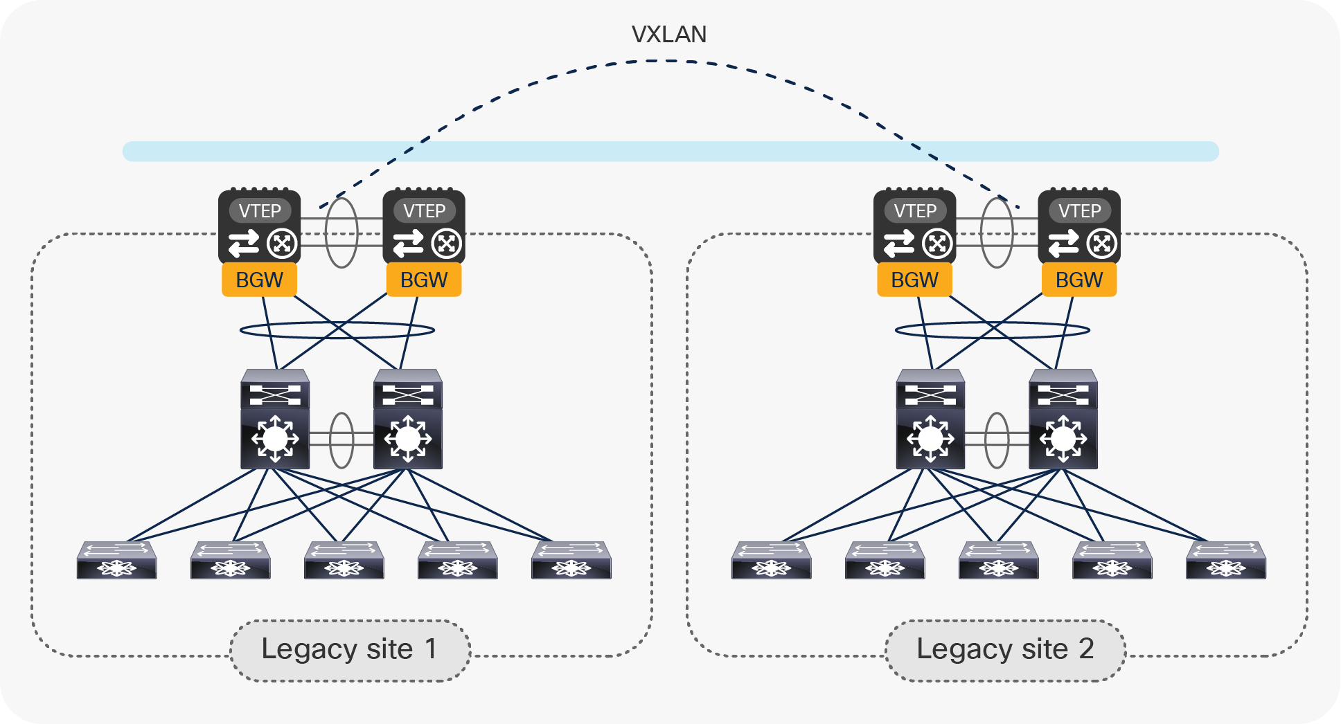
Use of vPC BGW nodes to connect multiple legacy data center sites
In this case, VXLAN EVPN and the use of vPC BGWs is positioned as a replacement of more traditional Data Center Interconnect (DCI) solutions, such as, for example, OTV or VPLS. The “Architectural benefits of introducing vPC BGWs for a DCI” section will highlight the main advantages of adopting this approach for fulfilling this specific use case.
The “Migrating legacy data centers to VXLAN EVPN fabrics using vPC BGWs” section will then discuss this specific use case in greater detail and will also clarify how, quite often, the deployment model shown above represents the first step of a migration procedure aiming to refresh the legacy technologies used inside each site and replace them with modern VXLAN EVPN fabrics.
vPC BGW for small-fabric deployments
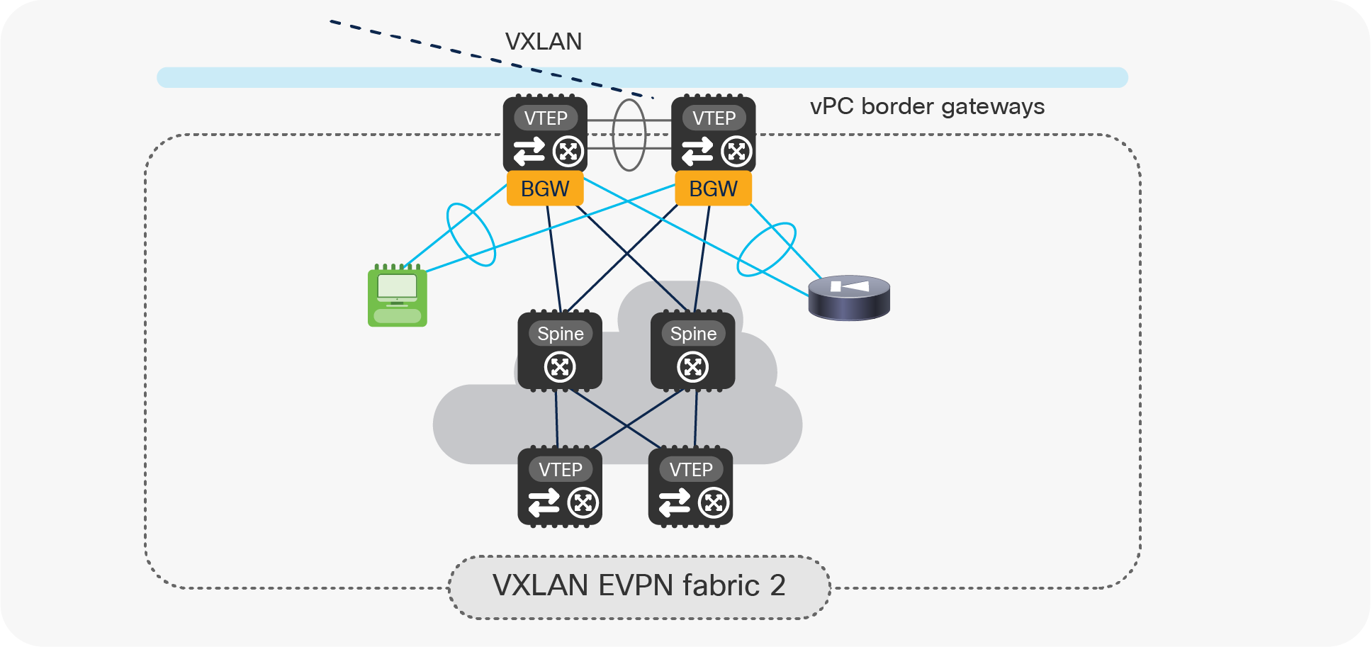
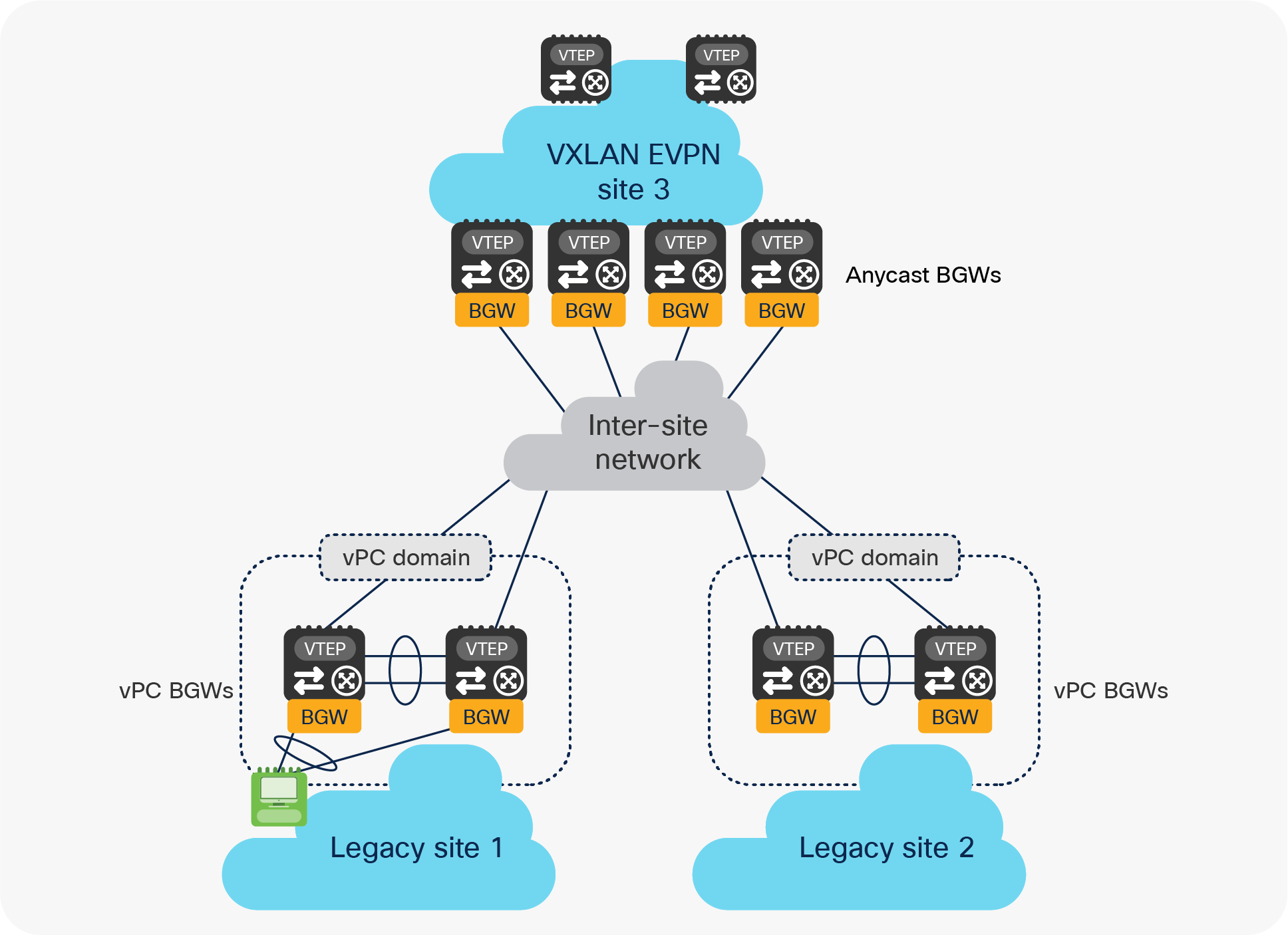
Another use case calling for the introduction of vPC BGW nodes is the establishment of Multi-Site connectivity between small fabrics, where it may not be possible (or cost effective) to deploy dedicated Anycast BGW nodes (Figure 7).
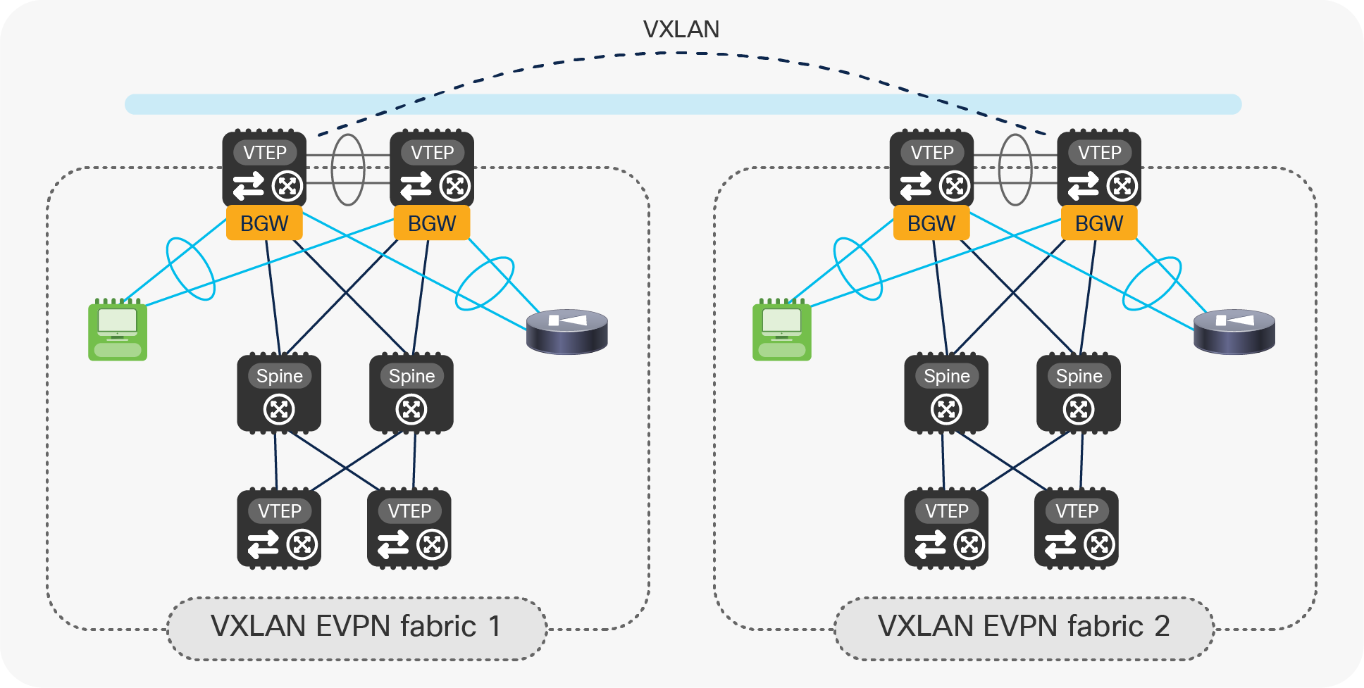
Deploying vPC BGW for small-fabric deployments
In this case, the pair of leaf nodes used for providing the BGW functionalities also support locally connected endpoints and service nodes, effectively functioning as compute and service leaf nodes.
While this is a fully supported deployment model, combining all those functionalities on the same pair of leaf nodes causes more complexity in terms of network design, configuration, and traffic flow debugging. Hence, the recommended and preferred approach for Multi-Site deployments is to have dedicated leaf nodes for the BGW function or, optionally, have those devices also provide Layer 3 connectivity toward the external network domain (that is, take the role of border leaf nodes).
Note: The deployment of the vPC BGW functionality on spine nodes is strongly discouraged. This deployment model is instead supported when deploying BGWs in Anycast Gateway mode, as discussed in greater detail as part of the document below: https://www.cisco.com/c/en/us/products/collateral/switches/nexus-9000-series-switches/white-paper-c11-739942.html
Architectural benefits of introducing vPC BGWs in a DCI use case
The introduction of vPC BGW nodes to provide DCI between legacy data-center sites offers the architectural benefits described in the following sections.
VXLAN EVPN Multi-Site uses a BGP EVPN control plane and a VXLAN data plane to extend Layer 2 and Layer 3 connectivity across sites. When connecting multiple legacy data centers, the use of vPC BGW nodes enables the hierarchical separation between the legacy data centers from both control-plane and data-plane perspectives.
Regarding the control plane, the Multi-Site selective advertisement feature offers tight control of the scope of Layer 2 and Layer 3 control plane advertisements. Only the MAC, IP host, and IP subnet prefix information for the Layer 2 segment and VRFs that have been locally defined on the BGW nodes are in fact advertised to the remote sites. This improves the overall scale of the Multi-Site solution and minimizes the amount of control plane activity across sites.
From a data plane forwarding perspective, the vPC BGW nodes leverage a VXLAN tunnel to extend connectivity between the legacy data centers. Traffic originating at an endpoint in the local legacy network and destined for an endpoint in a remote site is dynamically encapsulated into standard-based VXLAN packets and delivered across the transport network via the VXLAN tunnel.
Integrated Layer 2 and Layer 3 extension
With the use of the VXLAN BGP EVPN symmetric Integrated Routing and Bridging (IRB) feature, and multitenancy capabilities, the solution provides Layer 2 and Layer 3 extension leveraging the same technology. This greatly simplifies legacy networks integration. This is different from the use of more traditional DCI technologies that normally either provide a Layer 3-only or a Layer 2-only connectivity model.
For example, technologies such as VRF-lite, MPLS L3VPN, or LISP provide Layer 3-only connectivity. Technologies such as VPLS or Cisco OTV provide Layer 2 extension only. In summary, the introduction of vPC BGWs lets you easily achieve integrated Layer 2 and Layer 3 extension, workload mobility, and multitenancy between multiple legacy data center networks.
Whenever Layer 2 extension is implemented between multiple data center sites, the flooding of Layer 2 Broadcast, Unknown Unicast, and Multicast (BUM) traffic between the legacy data centers must be tightly controlled. This is critical to ensure that any issue (such as a broadcast storm) affecting the legacy network in a given site does not propagate to the other sites.
A special feature, called EVPN Multi-Site storm-control, is designed to control how much BUM traffic is allowed to propagate to other legacy sites. Layer 2 Broadcast, Unknown Unicast, and Multicast can be individually fine-tuned at the vPC BGW level to limit the propagation of those traffic types in aggregate toward the remote sites, as shown in Figure 8.
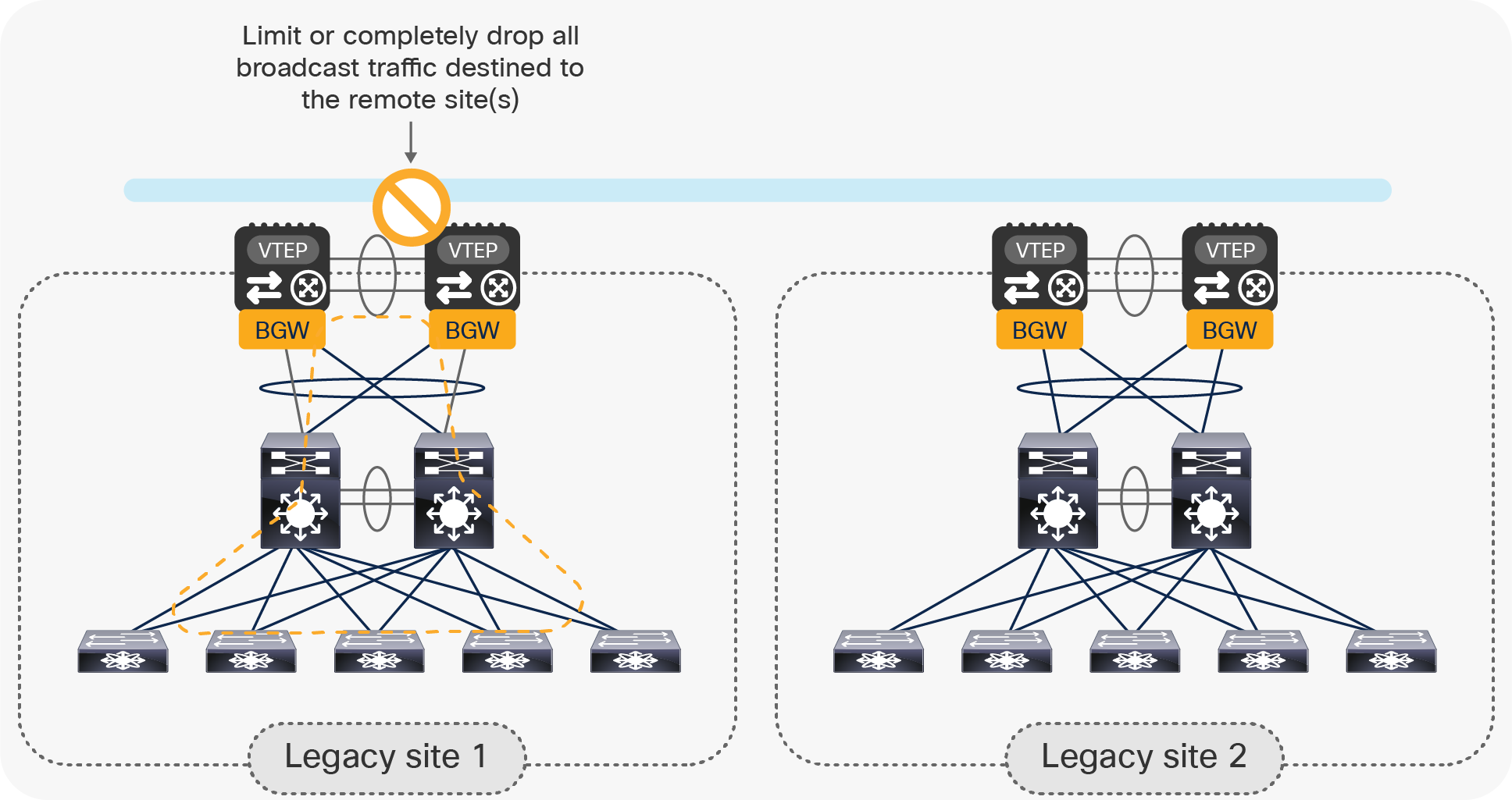
Preventing the propagation of a Layer 2 broadcast storm across sites
The use of a VXLAN tunnel established between pairs of vPC BGWs deployed across sites lets you simplify the functionality (and configuration) of the transport network interconnecting the data centers. The tunnel can, in fact, be built on top of any type of transport infrastructure, as long as it provides IP connectivity between remote vPC BGW nodes. Also, in order to accommodate the insertion of VXLAN encapsulation on the original traffic, the transport network needs to support an increased Maximum Transmission Unit (MTU) for the traffic it handles. Normally, 50 bytes is the MTU increase required, even if that mostly depends on the MTU of the original traffic originated by the endpoints connected to the legacy network.
Note: The vPC BGW nodes do not perform fragmentation and reassembly.
It is also worth noticing how the replication of BUM traffic between the legacy data centers is handled by the vPC BGW nodes by using Ingress Replication (IR) mode. Hence, there is no requirement for the underlay transport infrastructure to support multicast capability.
As mentioned earlier, each pair of vPC BGW nodes uses a Layer 2 vPC connection toward the local legacy network. Endpoints in remote legacy sites are learned as reachable via the vPC VIP of the remote vPC BGW pair as an EVPN next-hop address, as shown in Figure 9.
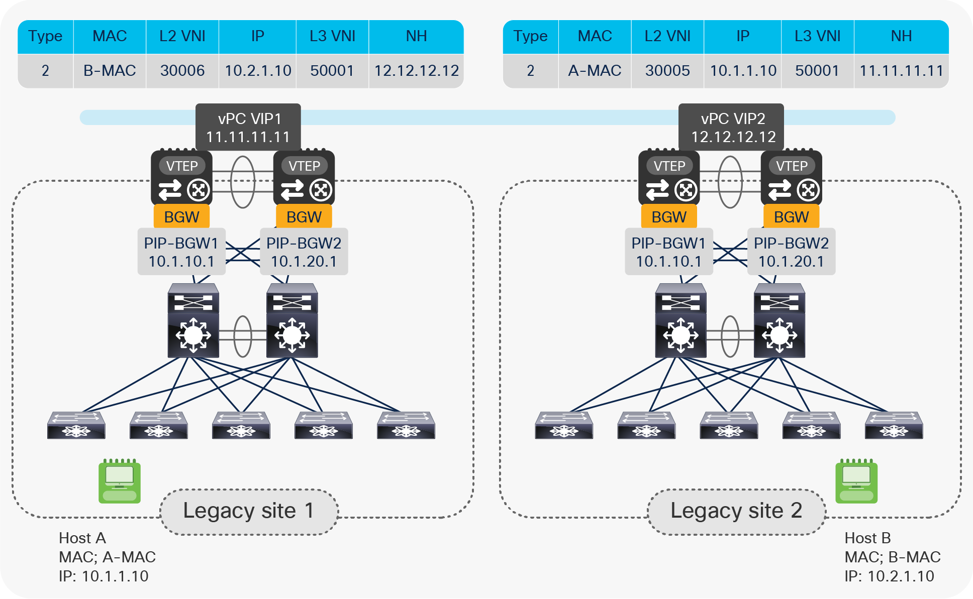
Learning remote endpoints with remote vPC VIP as EVPN next-hop
Note: Please note that for the specific DCI use case shown above, although the Multi-Site VIP is configured on the vPC BGW nodes in each site, it is not used to source or receive VXLAN traffic. This is because there is no deployment of any local VTEP leaf node, and all the local endpoints present in the legacy network are discovered as directly connected to the BGW nodes.
If one vPC BGW node fails, the remaining vPC BGW still owns the same vPC VIP address and is hence immediately available to take over forwarding duties for all of the data traffic. This greatly improves overall network resiliency and recovery time, because no overlay control plane activity is required for convergence.
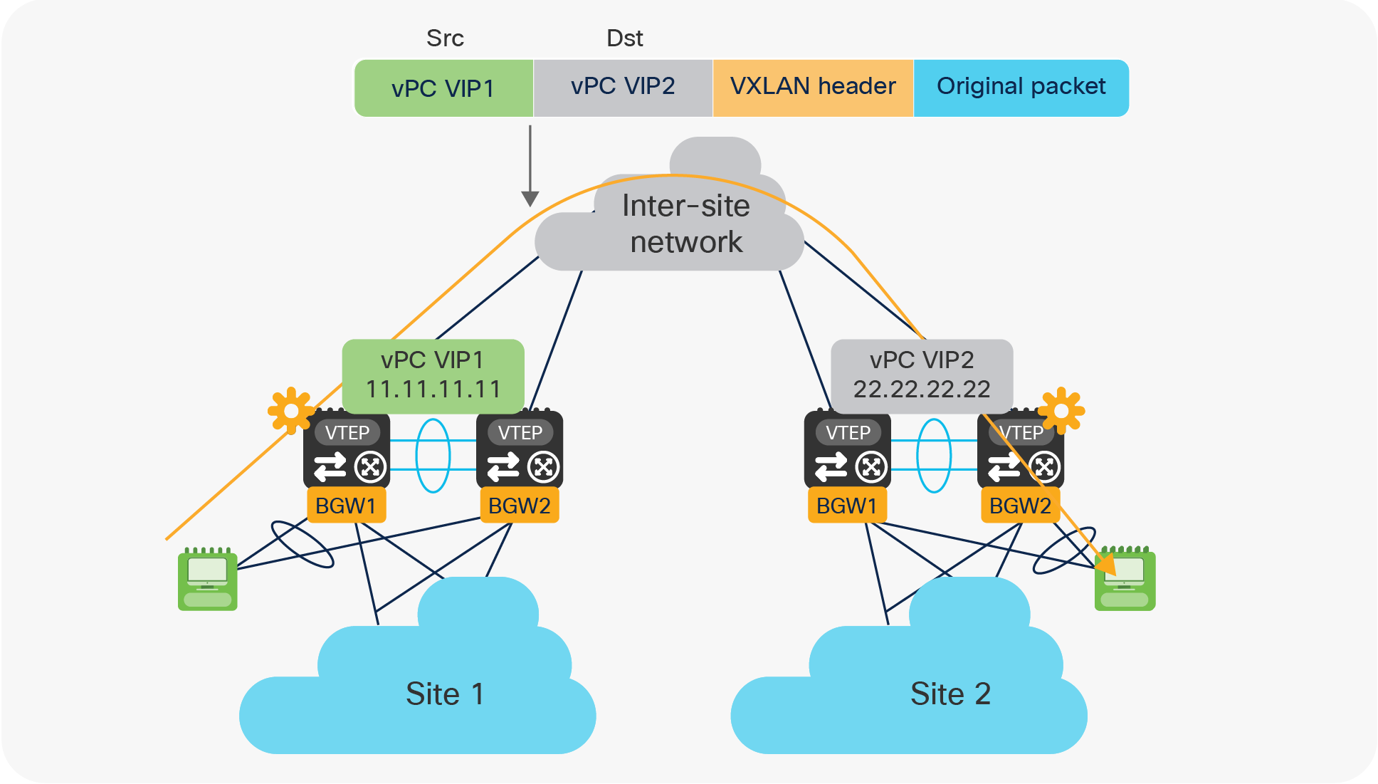
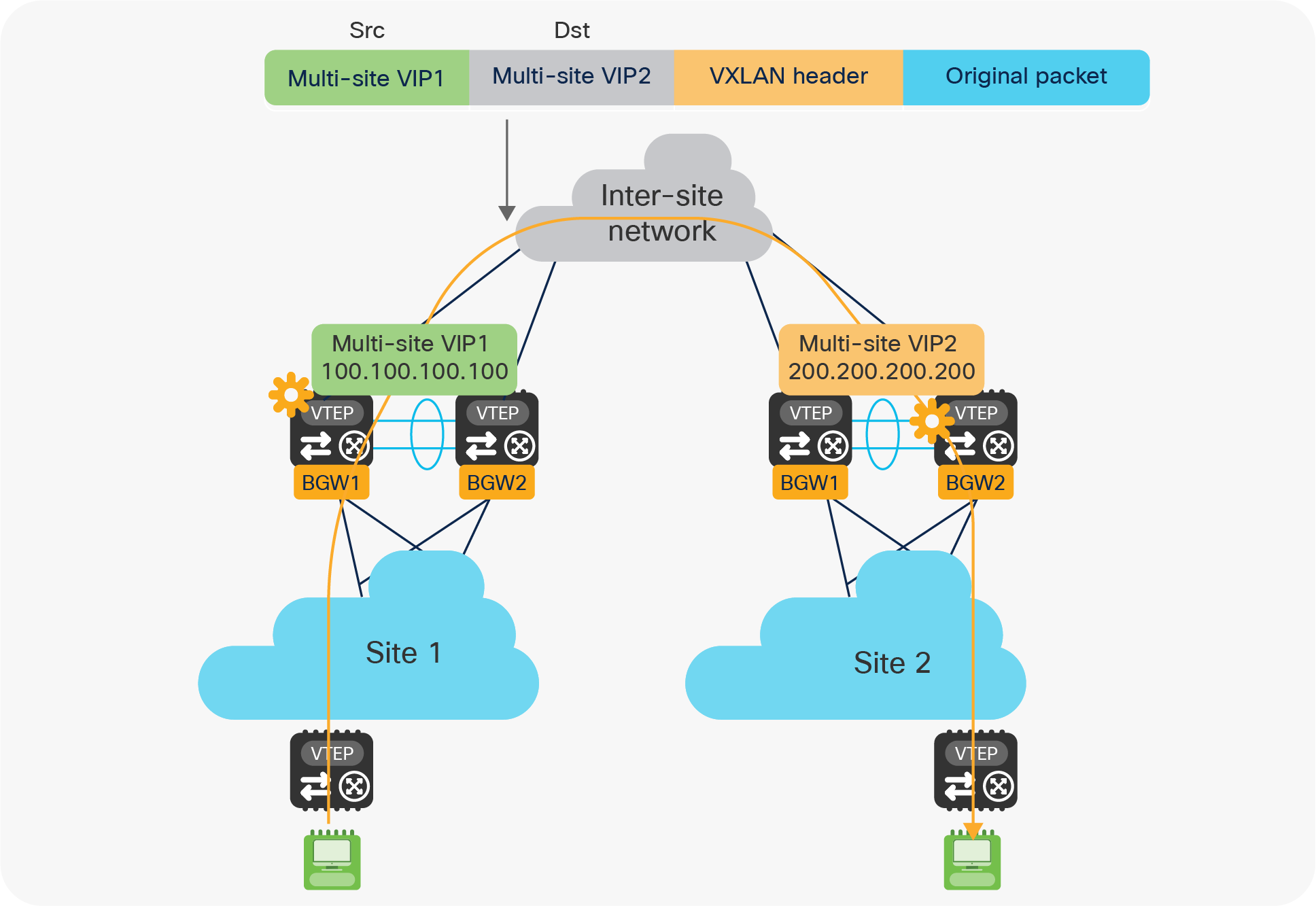
As previously stated, all of the intersite communications (either Layer 2 or Layer 3) between endpoints connected to the legacy networks leverage a VXLAN tunnel established between the two pairs of vPC BGW nodes deployed across sites.
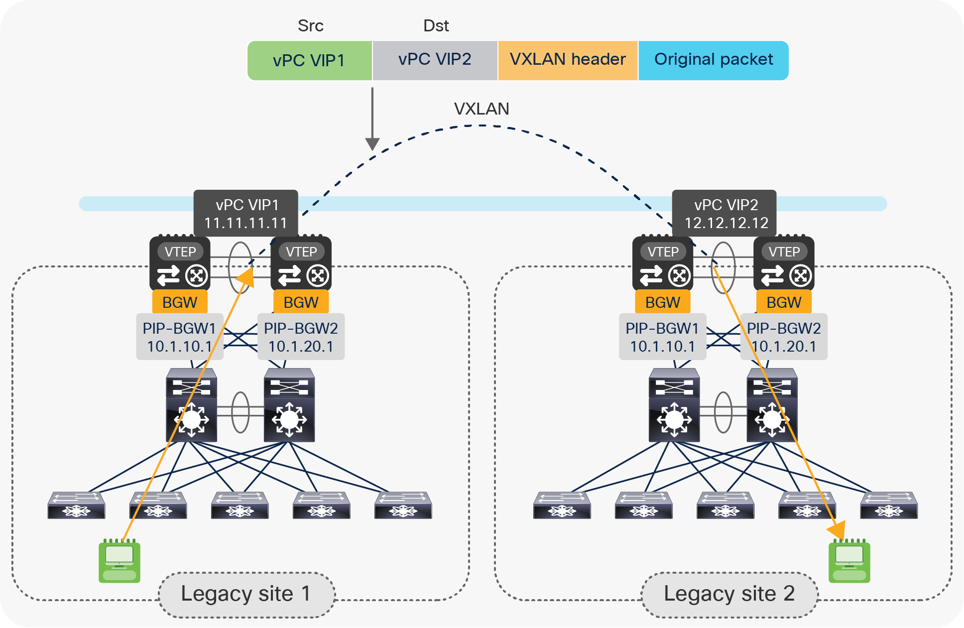
Use of vPC VIP addresses for intersite communication
As shown in Figure 10, the source and destination IP addresses used in the external IP header of the VXLAN traffic represent the vPC VIP addresses defined on each vPC BGW pairs. This may raise some concern about the distribution of traffic across the intersite network in case of the presence of equal-cost paths; the use of the same IP header information may lead to the incorrect belief that the same physical path is used for all intersite communications.
In reality, VXLAN traffic is User Datagram Protocol (UDP) encapsulated, and it is possible to build “entropy” into the packet by modifying the UDP source port information for each different traffic flow. This is achieved by calculating the hashing of the inner headers of the original packet and by using that value as the source UDP port for the VXLAN encapsulated traffic. This implies that different flows (characterized by different original header information) would be encapsulated with different source UDP port information, and this allows load balancing of traffic among different ECMP paths that may be available in the underlay transport IP network.
Loop prevention and STP isolation
With EVPN Multi-Site, it is mandatory to use eBGP EVPN as the control plane between the pairs of BGW nodes deployed across sites in order to exchange endpoints and IP subnet reachability information. The MAC address and IP prefix advertisements are originated from the local vPC BGW nodes with the vPC VIP as the next-hop address. With the BGP built-in as-path attribute, prefixes originating from one legacy site cannot be imported back to the same site; this provides a native loop prevention function at the control plane level.
From a data plane perspective, the vPC designated-forwarder election and split-horizon rules prevent BUM traffic from looping across sites.
Regarding integration with the Spanning Tree Protocol (STP), the vPC BGW nodes participate in the STP only on Classical Ethernet (CE) ports connecting them to the legacy network infrastructure. BPDU packets are not forwarded into the Multi-Site DCI overlay, hence each legacy data center represents a separate STP domain.
To prevent frequent STP port status changes on the vPC BGWs, moving the STP root from the legacy network to the pair of Multi-Site vPC BGWs is recommended. This also proves useful when a Layer 2 backdoor connection between the two legacy sites has been created; STP will allow blocking of the Layer 2 backdoor link to prevent creation of an end-to-end loop. It is worth noticing how the behavior shown in Figure 11, below, requires a couple of specific configurations to be applied on the vPC BGW nodes:
● The STP priority should be configured to be the same on the vPC BGWs deployed in both data center sites.
● The vPC domain number should also be the same, as this would allow assigning the same Bridge-ID to both pairs of vPC BGWs.
As a consequence of the configuration specifics given above, both pairs of vPC BGWs would be seen as the same STP root device when a Layer 2 backdoor between the legacy networks has been created, causing STP to block the link.
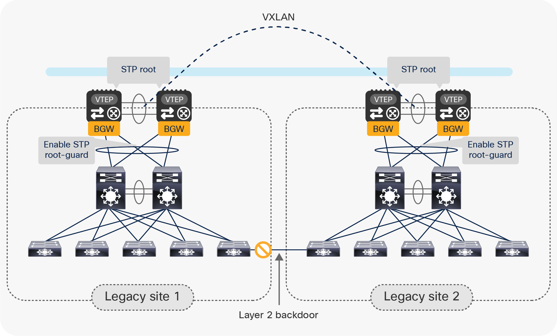
Use of STP to prevent the creation of an end-to-end loop
As shown above, it is also a best-practice recommendation to configure STP Root-Guard on the logical vPC connections between each pair of the BGW nodes and the legacy network, to protect against the erroneous configuration of a switch in the legacy infrastructure claiming the STP root role.
Note: The edge interfaces of the access layer switches in the legacy network should always carry Cisco® best-practice configurations, including the enablement of STP BPDU-Guard. That way, the link will be disabled as a result of the creation of a Layer 2 backdoor even in scenarios where the STP root was not deployed on the vPC BGW devices.
The VXLAN EVPN Multi-Site architecture has been designed to be able to scale. The maximum number of sites supported as of Cisco NX-OS release 7.0(3)I7(1) is 10. Starting with Cisco NX-OS release 9.2(1), this number includes both legacy data centers (leveraging a pair of vPC BGW nodes) or VXLAN EVPN fabric data centers, usually deploying multiple Anycast BGW nodes.
Note: The maximum number of supported sites will continue to increase in future Cisco NX-OS releases. Please be sure to always check the latest scalability information, which is available on Cisco.com.
Migrating legacy data centers to VXLAN EVPN fabrics using vPC BGWs
In the previous sections, we have discussed how the VXLAN EVPN Multi-Site technology is designed with DCI use cases in mind. This section will present in detail the procedures required to migrate legacy data centers to new-generation VXLAN EVPN fabrics with the introduction of vPC BGW nodes. Each step of the migration procedure will be discussed in detail and will offer specific configuration information.
Note: All of the configuration samples are based on Cisco NX-OS 9.2(1).
The assumption is that the legacy sites are already interconnected (Layer 2 and Layer 3), leveraging traditional DCI connections (OTV, vPC, VPLS for Layer 2 and VRF-Lite or MPLS VPN for Layer 3). One of the goals of the migration is to replace those DCI connections with the modern VXLAN EVPN Multi-Site option.
Step 1: Insert a pair of vPC BGWs in each legacy site, using Layer 2 double-sided vPC
The initial assumption is that the legacy network is deployed with a classic aggregation/access layer design with the default gateway deployed on the aggregation switches.
Note: The same considerations for this step of the procedure would apply in a scenario where the first-hop gateway for the endpoints was deployed on a firewall node (usually connected to the aggregation layer switches).
Connect the pair of vPC BGW nodes to the pair of aggregation switches using a Layer 2 double-sided vPC, as shown in Figure 12.
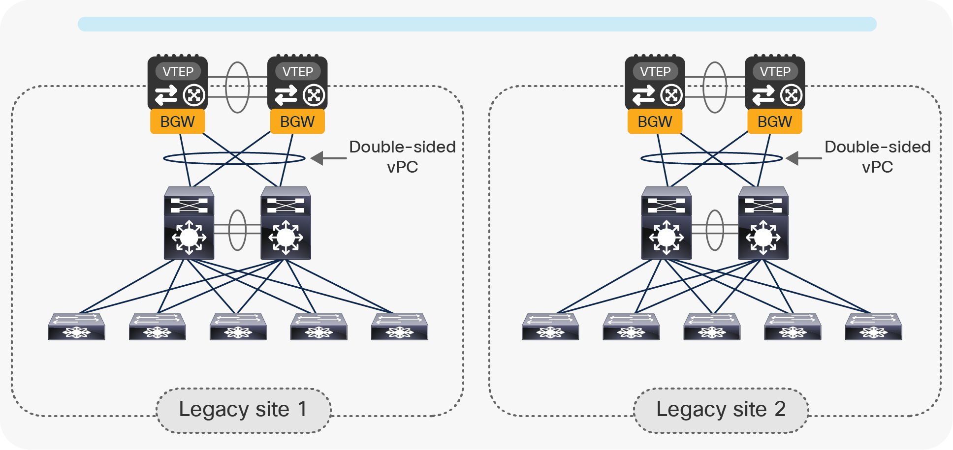
Connecting the vPC BGW nodes to the legacy network using a Layer 2 double-sided vPC
The advantage of using the double-sided vPC connection is that a single Layer 2 logical connection exists between the BGW nodes and the legacy network, so all of the available links actively forward traffic between the two networks without requiring STP to block any path.
When the aggregation switches do not support vPC or MLAG, local port-channels can be created from each aggregation switch and the pair of vPC BGW nodes, as shown in Figure 13.
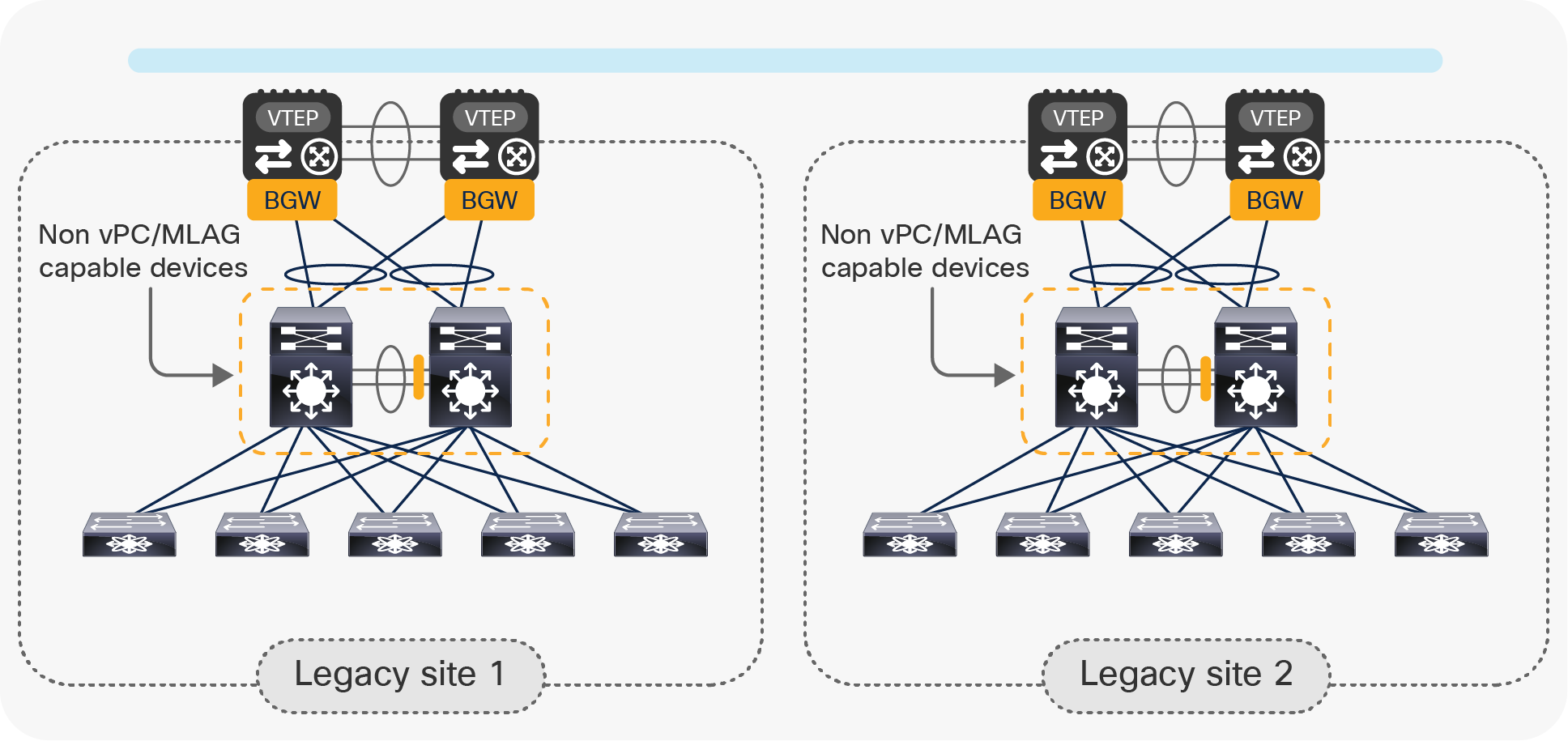
Aggregation switches using local port-channels to connect to the vPC BGW nodes
STP would then need to break the Layer 2 loop created between the aggregation switches and the BGWs, and this would cause one of the two local port-channels to go into an STP blocking state.
The rest of this document will focus on the first recommended option: leveraging the double-sided vPC connection. The BGW nodes must be configured as part of the same vPC domain following the best-practice configuration shown below.
| feature vpc
vpc domain 1 peer-switch peer-keepalive destination 172.19.217.122 \ source 172.19.217.123 delay-restore 150 peer-gateway auto-recovery reload-delay 360 ipv6 nd synchronize ip arp synchronize
interface port-channel10 vpc peer-link |
Define the vPC domain and properly tune the delay-restore and the reload-delay timers to optimize convergence after a vPC peer reload event. |
| vlan 3600
interface Vlan3600 description VPC-Peer-Link SVI no shutdown mtu 9216 no ip redirects ip address 10.1.10.49/30 no ipv6 redirects ip ospf network point-to-point ip router ospf UNDERLAY area 0.0.0.0 ip pim sparse-mode
system nve infra-vlans 3600
router bgp 65501 neighbor 10.1.10.50 remote-as 65501 address-family ipv4 unicast |
Establish an iBGP session in the underlay domain between the vPC peer devices. This should be configured in addition to an already existing IGP peering (OSPF, IS-IS, etc.) to handle traffic recovery in very specific failure scenarios. |
Step 2: Configure vPC BGWs DCI underlay network
The network interconnecting the data center sites (site-external network) is a transport network that provides underlay reachability between the pairs of vPC BGWs deployed at different sites. The vPC BGW nodes must establish a routing peering with the first-hop Layer 3 devices part of the intersite network, as highlighted in Figure 14.
Note: In the specific case where dark fiber connections or Dense Wavelength Division Multiplexing (DWDM) circuits were available between sites, the two pairs of vPC BGW nodes could be connected directly via Layer 3 point-to-point interfaces.
Connecting the vPC BGW nodes to the site-external underlay network
The routing peering with the first-hop router in the site-external underlay network can leverage the routing protocol of choice (for example, OSPF, IS-IS, EIGRP, etc.). However, given that EBGP is required for the overlay peering between sites (as discussed in a following section, below), it is quite common to use eBGP peering as underlay protocol.
Note: Those specific considerations apply to the site-external network and not to the site-internal one, where it is always a best-practice recommendation to deploy an IGP (OSPF, IS-IS, or EIGRP) as underlay protocol and iBGP as overlay protocol.
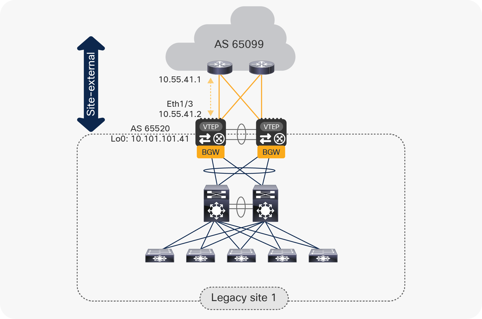
The example below shows the configuration required for establishing EBGP peering between a vPC BGW and the directly connected router in the site-external network. The network diagram in Figure 14 is used as reference.
| interface Ethernet1/3 no switchport mtu 9216 ip address 10.55.41.2/30 tag 54321 evpn multisite dci-tracking |
Define the site-external underlay interface(s) connecting the vPC BGW to the external Layer 3 core. Adjust the MTU setting of the interface(s) to a value that accommodates the specific requirements (the minimum value is 1500 bytes plus the 50 bytes of VXLAN encapsulation). Point-to-point IP addressing is used for site-external underlay routing (point-to-point IP addressing with /30 is shown here). The IP address is configured with an associated tag to allow easy selection for redistribution into the intersite underlay routing protocol. Note: EVPN Multi-Site interface tracking (evpn multisite dci-tracking) is required on the interface(s) connecting to the external Layer 3 core to detect the scenario where a given vPC BGW node gets isolated from the external network. |
| router bgp 65520 router-id 10.101.101.41 log-neighbor-changes address-family ipv4 unicast redistribute direct route-map RMAP-REDIST-DIRECT maximum-paths 4 neighbor 10.55.41.1 remote-as 65099 update-source Ethernet1/3 address-family ipv4 unicast |
Define the BGP routing instance with a site-specific autonomous system. The BGP router ID should match the loopback0 CP IP address. Activate the IPv4 unicast global address family (VRF default) to redistribute into BGP the required loopback prefixes and, if needed, the IP addresses of the physical interfaces. Enable BGP multipathing (maximum-paths command). The eBGP neighbor configuration is performed by specifically selecting the source interface for this single-hop eBGP peering (update-source command). This allows tearing down of the neighborship as soon as the physical link fails. |
| route-map RMAP-REDIST-DIRECT permit 10 match tag 54321 |
The redistribution from the locally defined interfaces (direct) to BGP is achieved through route-map classification. Only IP addresses with a matching tag are redistributed. |
The same configuration must be applied to all the Layer 3 interfaces connecting the BGW nodes to the site-external network. Also, it is assumed that the proper underlay configuration is also done on all the Layer 3 devices that are part of the site-external network.
Step 3: Configure vPC BGWs DCI overlay network
EVPN Multi-Site mandates the use of MP-eBGP EVPN as the overlay control-plane between the BGW nodes deployed in separate sites. This overlay control-plane is used to exchange reachability information for the VRFs (IP subnets and/or host routes) and Layer 2 VNIs (MAC addresses). The example in Figure 15 shows the establishment of the EVPN peering between two BGW nodes part of separate sites. A full mesh of EVPN adjacencies between the two pairs of vPC BGW nodes is the best practice recommendation.
Note: Depending on the number of interconnected sites, it may become advantageous to deploy a pair of “Route-Server” devices in the site-external network to perform the role of route-reflectors and avoid the creation of those full-mesh adjacencies between the BGW nodes. More information about the deployment of the Route-Server nodes can be found in the “VXLAN EVPN Multi-Site Design and Deployment White Paper.”[1]
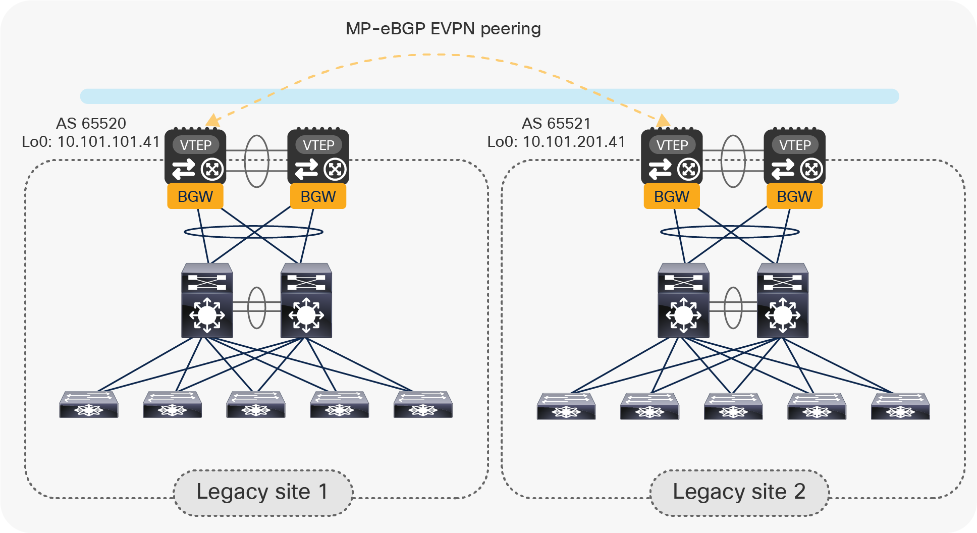
Establishment of MP-eBGP EVPN peering between vPC BGW nodes in separate sites
Below is the specific configuration required for the establishment of the EVPN peering shown in Figure 15:
| router bgp 65520 router-id 10.101.101.41 log-neighbor-changes neighbor 10.101.201.41 remote-as 65521 update-source loopback0 ebgp-multihop 5 peer-type fabric-external address-family l2vpn evpn send-community send-community extended rewrite-evpn-rt-asn |
Configure the remote BGW neighbor(s) with the EVPN address family (L2VPN EVPN) enabled. The IP address specified for the neighbor represents its loopback0 CP IP address. The eBGP neighbor configuration is performed by specifying the source interface as the local loopback0. Since the remote BGW device(s) could potentially be multiple Layer 3 hops away, you must increase the BGP session TTL setting to an appropriate value (ebgp-multihop command). The peer-type fabric-external configuration is required for each remote Multi-Site BGW neighbor to enable the rewriting of next-hop IP and next-hop MAC (RMAC) for all the overlay prefixes advertised to remote site BGW(s). Finally, the rewrite-evpn-rt-asn configuration applied under the EVPN address-family is required to enable the rewriting of Route-Target values for prefixes advertised to remote BGWs (based on BGP Neighbors Remote ASN). |
Note: The same configuration described above must be applied for all the remote BGW nodes, unless Route-Servers are introduced.
Step 4: Configure vPC BGWs for DCI Layer 2 extension across sites
Once the underlay and overlay control-plane configurations are completed, the vPC BGW nodes should be first configured to provide Layer 2 extension services between the legacy sites. This is done by allowing the VLANs requiring extension to the vPC connection (Layer 2 trunk) established between the BGW nodes and the legacy network and by associating each VLAN to a L2 VNI segment on the BGW nodes.
Please note that EVPN Multi-Site replicate overlay BUM traffic uses Ingress Replication (IR) mode in the DCI overlay. The DCI underlay network does not need to have multicast capability. Also, it is possible to configure the aggregate storm-control functionalities to control and limit the propagation of Layer 2 BUM traffic across sites.
For EVPN Multi-Site vPC BGWs, you must configure the commands evpn multisite border-gateway and multisite border-gateway interface on the vPC BGWs.
The example below shows the configuration required for Layer 2 extension on vPC BGW VTEPs.
| evpn multisite border-gateway 1 delay-restore time 300 |
Define the site-id: the pair of vPC BGWs on the same site must use the same site-id value. The “delay-restore time” command is used to administratively keep the Multi-Site VIP shut down when the BGW is reloaded for the number of seconds given; in this case, 300. |
| interface loopback100 description Multi-Site VIP ip address 10.10.12.1/32 tag 54321 ip pim sparse-mode
interface loopback1 ip address 10.10.10.1/24 tag 54321 ip address 10.10.11.1/24 secondary tag 54321 |
Define the loopback interface to be used as Multi-Site virtual IP address (Multi-Site VIP), and the loopback interface to be used as Primary IP address (PIP) and vPC virtual IP address (vPC VIP). |
| vlan 5 vn-segment 30005
vlan 6 vn-segment 30006 |
Map the VLANs to the corresponding Layer 2 VNIs. (Those VLANs must be trunked on the vPC connection established with the legacy network; this configuration is not shown here.) |
Note: If those VLANs are already extended via a traditional DCI solution (OTV, VPLS, etc.), it is critical to avoid the creation of an end-to-end Layer 2 loop between data center sites. This can be achieved in a couple of different ways (on a VLAN-by-VLAN basis):
● Disabling the VLAN extension through the traditional DCI solution and start using Multi-Site to provide Layer 2 connectivity between data centers. This would be the recommended approach, as the end goal should eventually be to replace the legacy DCI solution.
● Keep the VLAN extension function via the traditional DCI solution and avoid trunking the VLAN on one of the two vPC connections between the legacy networks and the vPC BGW nodes. This may be useful in the initial phases of the migration when the default gateway for the endpoints belonging to the VLAN is still offered by the aggregation layer devices in the legacy network, and when some specific functionalities (such as HSRP filtering offered by OTV) are in place to ensure that a local default gateway is offered in each data center site.
| interface nve1 no shutdown host-reachability protocol bgp source-interface loopback1 multisite border-gateway interface loopback100 global ingress-replication protocol bgp member vni 30005 multisite ingress-replication ingress-replication protocol bgp member vni 30006 multisite ingress-replication mcast-group 239.1.1.1 |
Associate the Layer 2 VNIs with the NVE interface (VTEP) for selective advertisement. Only the associated Layer 2 VNIs are extended across the DCI. Configure the replication mode for intersite BUM traffic, which must be ingress-replication. BUM replication for Layer 2 VNI (L2VNI) must always be configured; for example, mcast-group or ingress-replication protocol bgp. A global default can be set per NVE to simplify the configuration (global ingress-replication protocol bgp); per-VNI configuration overrides the global value. |
Step 5: Enable Anycast Gateway on vPC BGWs and keep it in shutdown state
Often the desire is to migrate the first-hop gateway functionalities from the aggregation switches in the legacy network to the vPC BGW nodes. This can be done both for IP subnets that are locally defined in a site and for IP subnets that must be extended across sites (as shown in the configuration step previously discussed).
Legacy networks typically use a First-Hop Redundancy Protocol (FHRP) such as Hot Standby Router Protocol (HSRP), Virtual Router Redundancy Protocol (VRRP), or Gateway Load-Balancing Protocol (GLBP) on the aggregation switches. The vPC BGWs use a Distributed Anycast Gateway (DAG) to provide a consistent first-hop gateway.
Note: For IP subnets that are extended across sites, the use of a DAG also allows the provision of a local and consistent default-gateway function that prevents the creation of traffic hair-pinning across the DCI network.
The coexistence of these different first-hop gateway approaches is not supported. Hence, the first step for the migration of the default gateway functionality on the vPC BGW nodes consists in creating the Anycast gateway SVIs that would initially be kept in a shutdown state, as shown in Figure 16.
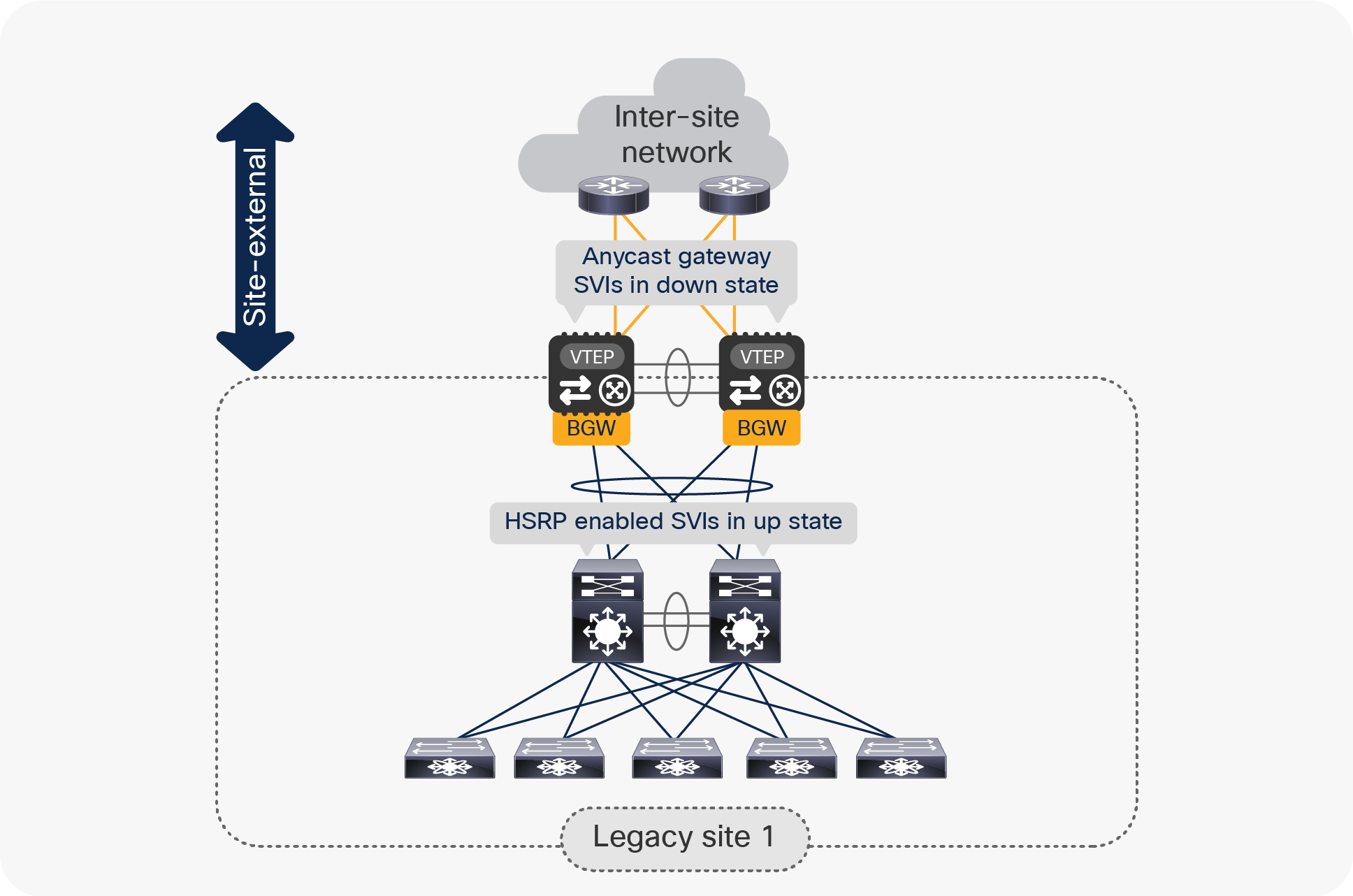
Coexistence of Anycast Gateway SVIs and HSRP Gateway SVIs
The sample below shows the creation of the required Layer 3 configuration on the vPC BGW nodes.
| fabric forwarding anycast-gateway-mac 2020.0000.00AA |
Define the Anycast Gateway MAC address (2020.0000.00AA in this example) for all the defined tenant SVIs. |
| vlan 2001 vn-segment 50001 |
Map one of the reserved VLANs to the L3 VNI to be used for a given VRF (tenant-1). |
| vrf context tenant-1 vni 50001 |
Define the tenant VRF and associate it with the defined L3 VNI. |
| interface nve1 member vni 50001 associate-vrf |
Associate the L3 VNI to the NVE interface. |
| interface Vlan5 shutdown vrf member tenant1 ip address 10.1.5.1/24 tag 12345 fabric forwarding mode anycast-gateway |
Define the SVI to be used as Anycast Gateway and keep it in shutdown mode. Notice the use of a specific tag to facilitate the redistribution of the IP subnet prefix into the intersite overlay control-plane. |
| router bgp 65520 vrf tenant-1 address-family ipv4 unicast redistribute direct route-map FABRIC-RMAP-REDIST-SUBNET maximum-paths ibgp 2 address-family ipv6 unicast redistribute direct route-map FABRIC-RMAP-REDIST-SUBNET maximum-paths ibgp 2 |
Configure the VRF under the BGP process to be able to start exchanging L3 prefixes with the remote BGW nodes. Note: max-path is needed only for a local fabric. |
| route-map FABRIC-RMAP-REDIST-SUBNET permit 10 match tag 12345 |
Define the route-map used to redistribute IP subnet information into the EVPN control plane. |
Step 6: Migrate first-hop FHRP Gateway in the legacy site to the vPC BGW Anycast Gateway
Follow the procedure below to migrate FHRP Gateway in the legacy site to Anycast Gateway on the pair of vPC BGWs. This can be done on a per-IP subnet basis on the aggregation layer switches.
| interface vlan 20 vrf member Tenant-A ip address 192.168.20.201/24 hsrp 10 ip 192.168.20.1 mac-address 2020.0000.00aa |
Align all FHRP Gateway MAC and IP addresses with the Multi-Site vPC BGW distributed IP Anycast Gateway (DAG) configuration. You must use the same virtual MAC address for all of the different IP subnets, because the Anycast Gateway virtual MAC address is a global configuration parameter on VXLAN EVPN VTEPs. |
Note: If the aggregation switches in the legacy network do not support a static MAC configuration for the defined SVIs, it is possible to change the configuration to have all the SVIs using the same HSRP group. That way, the same vMAC will be dynamically created (as it is directly related to the HSRP group number), and it would then be possible to modify the global vMAC value defined on the BGW nodes to match that value.
After adjusting the virtual MAC in the legacy site, implement a state change (switch from standby to active) to force a gratuitous ARP (GARP) process from FHRP. This allows the MAC addresses in the endpoint ARP caches to be updated to match the newly created virtual MAC.
Establish per-VRF routing peering between the aggregation layer switches in the legacy network and the vPC BGWs. This is required when performing the default gateway migration to the vPC BGWs one IP subnet at a time, in order to route traffic between IP subnets that still have the default gateway enabled on the aggregation layer switches and IP subnets that have their default gateways migrated to the vPC BGWs.
Note: This is not needed if all of the subnets are migrated at once.
For establishing this Layer 3 peering, the recommendation is to use a separate pair of dedicated Layer 3 interfaces, as shown in Figure 17. Separate sub-interfaces can be defined in a multitenant (that is, multi-VRF) deployment.
Use of dedicated Layer 3 links between vPC BGW nodes and the legacy network
Below is the configuration required on the aggregation switches; a matching configuration, obviously, is needed on the vPC BGWs. Notice that the use of IPv4 BGP for establishing the per-VRF peering would allow an automatic redistribution with the overlay EBGP EVPN control plane used with remote BGW nodes.
| interface Ethernet1/1.10 description L3 Link to vPC BGW1 (T1) encapsulation dot1q 10 vrf member Tenant-1 ip address 192.168.36.4/31
router bgp 65520 router-id 100.100.100.1 vrf Tenant-A neighbor 192.168.36.5 remote-as 65520 address-family ipv4 unicast |
Create a subinterface per tenant and enable exchange of IPv4 routes with the BGP neighbor. |
Note: The best practice is to create a full mesh of L3 links between the aggregation layer switches and the vPC BGWs to speed up convergence in case of a link or node failure.
At this point, it is possible to disable the FHRP SVIs on the aggregation layer and enable the DAG SVIs on the vPC BGW nodes. This step will move all first-hop gateway operations to the vPC BGWs connected to the aggregation layer. As previously mentioned, this can be done on a per-subnet basis.
It is also recommended to move the Spanning Tree root from the aggregation layer to the vPC BGWs, as previously discussed. The legacy site’s Ethernet network is now southbound of the BGW.
Note: Changes to FHRP, to connections to the BGW, to the STP root, or to routing peering between sites may introduce short-term disruption to existing network operations. You should make these changes during maintenance windows.
At this point, the migration procedure to extend Layer 2 and Layer 3 connectivity between the legacy data-center sites is completed. The high-level steps described below are optional and needed only when the desire is to introduce VXLAN EVPN for intrasite communication in one (or all) legacy data centers.
Step 7: Transition legacy data centers to new Cisco Nexus 9000 Series Switches and new fabric technology
Once the legacy data centers are interconnected through the Multi-Site extension provided by the vPC BGW nodes, it is then possible to slowly phase out the legacy networks and replace them with new fabric technologies, for example, a VXLAN BGP EVPN fabric or a Cisco ACI™ fabric. The procedure discussed below focuses on the former scenario.
Note: The same procedure applies in cases where only one (or a subset) of the interconnected legacy sites needs to be migrated to a full VXLAN EVPN fabric.
● Introduce VXLAN EVPN spines and additional VTEPs in each legacy site and start building a new VXLAN EVPN fabric.
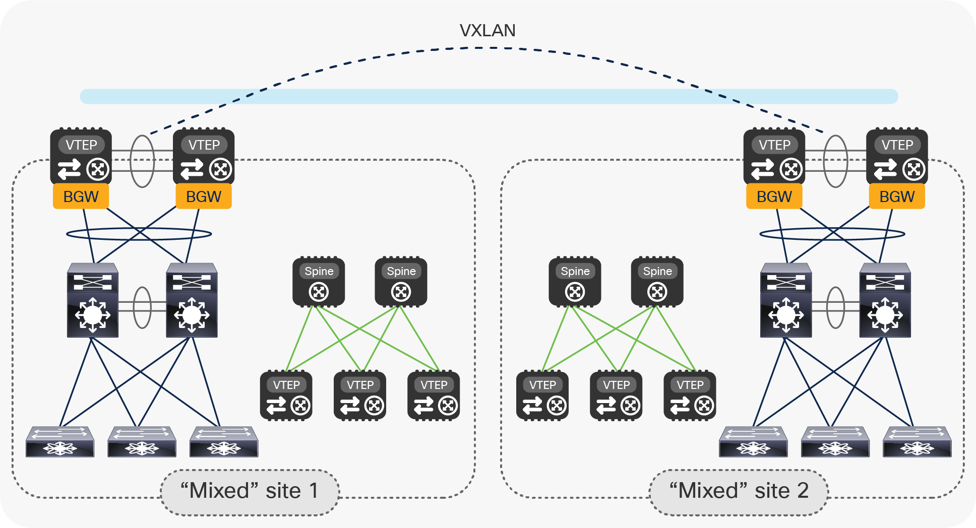
Start building a new VXLAN EVPN fabric in each date center location
● Connect the new fabric spines to the pair of vPC BGWs with point-to-point Layer 3 links. Modify the configuration on the vPC BGWs to integrate with the new VXLAN EVPN fabric. Those changes do not affect the existing connectivity between the legacy networks.
Initial step of the legacy data center migration to VXLAN EVPN fabrics with vPC BGW nodes
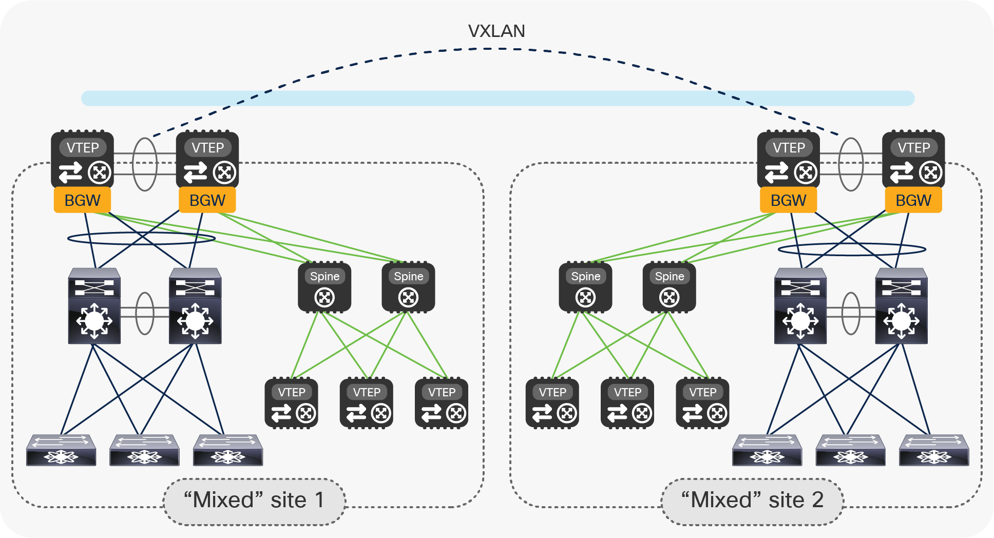
● Once the legacy network is locally connected to the newly created VXLAN EVPN fabric, it is possible to start migrating applications and services between the two. Figure 20 highlights the end state of the migration procedure, where all the applications and services have been relocated into the new VXLAN EVPN fabrics and the old legacy network devices have been decommissioned.
End state of the legacy data center migration to VXLAN EVPN fabrics with vPC BGW nodes
Notice that at this point the vPC BGW nodes perform the full BGW duties as they allow extending connectivity between endpoints connected to local and remote VTEP devices. This is in contrast with the scenario shown in Figure 6, where there was no presence of VTEP nodes inside the local sites.
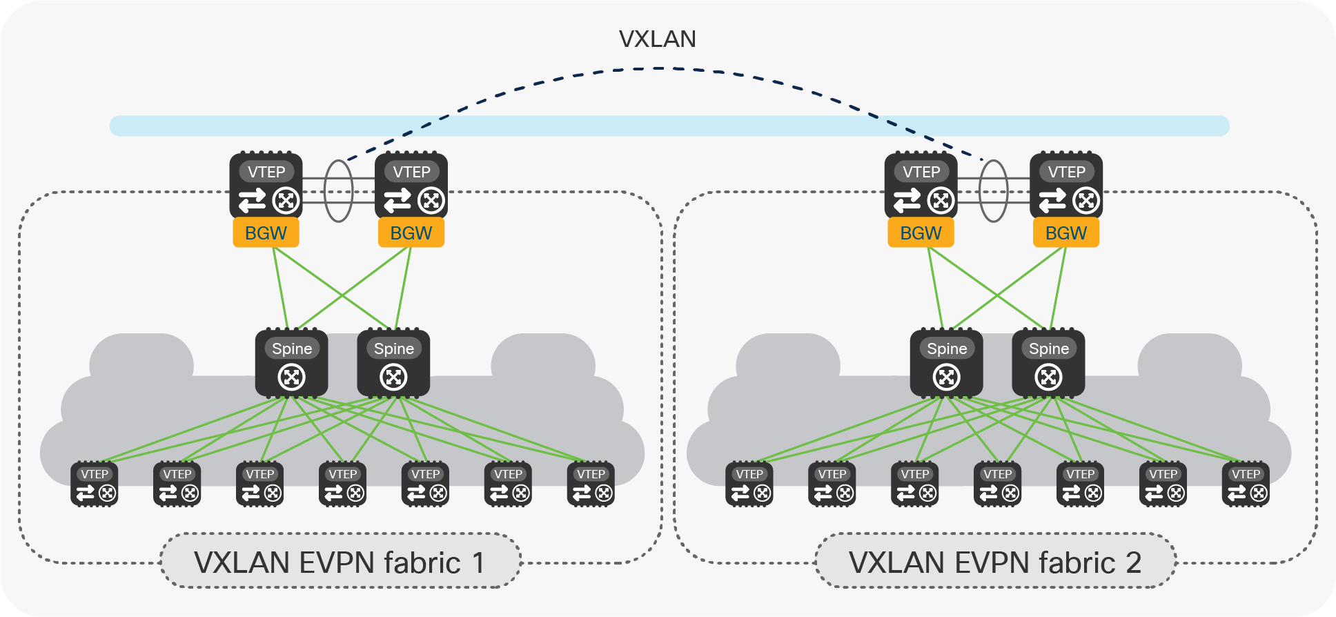
● The last optional step consists in removing the vPC configuration on the BGW nodes, to convert them to Anycast BGWs. (See Figure 21.)
Converting vPC BGWs to Anycast BGWs
● This is the recommended deployment model for interconnecting VXLAN EVPN fabrics, but it is only possible if there are no endpoints connected to the original vPC BGWs that are using them as their default gateway.
● Note: The conversion to Anycast mode can be performed one BGW at the time, in order not to disrupt the Layer 2 and L3 connectivity between sites.
Data center deployments are rapidly transitioning to Cisco Nexus 9000 Series Switches–based infrastructures with higher speeds, greater port density, and feature richness. The Cisco VXLAN EVPN Multi-Site solution on Cisco Nexus 9000 Series Switches is designed from ground up to address the many use cases of fabric scaling, compartmentalization, and Data Center Interconnect (DCI).
This document introduced the specific Multi-Site deployment option leveraging vPC Border Gateways (BGWs) to address various scenarios where their use is beneficial, with specific focus on the provision of a modern solution to interconnect separate data enter sites (the DCI use case).
While the use of Anycast BGW is still the recommended approach for interconnecting VXLAN EVPN fabrics, the introduction of vPC BGWs offers advantages in the specific cases where Layer 2 and Layer 3 connectivity must be extended between VXLAN EVPN fabrics and legacy data center sites built with traditional technologies (such as STP, vPC, or Cisco FabricPath, to name a few options).
At the same time, the vPC BGWs may also be used to replace such traditional DCI technologies for interconnecting legacy data center networks (that is, even before introducing the VXLAN EVPN technology inside the data center network), in virtue of the functionalities they introduce related to network control, VTEP masking, and BUM traffic enforcement that help making EVPN Multi-Site architecture a powerfully efficient DCI technology.
[1] VXLAN EVPN Multi-Site Design and Deployment White Paper
[2] vPC Best Practices Configuration Guide
[3] Migrating Cisco Classic Ethernet or FabricPath Environments to VXLAN BGP EVPN White Paper
From FabricPath: https://www.cisco.com/c/en/us/td/docs/dcn/whitepapers/migrating-fabricpath-environment-vxlan-bgp-evpn.html
From Classic Ethernet: https://www.cisco.com/c/en/us/td/docs/dcn/whitepapers/migrating-classic-ethernet-to-vxlan-bgp-evpn-white-paper.html
Appendix: VXLAN EVPN Multi-Site with vPC BGW design and deployment considerations
The introduction of the vPC Border Gateway functionality provides an alternative model to interconnect data center sites, in addition to the previously available deployment of Anycast Border Gateways (Figure 22). The different variations of BGW can be mixed in an EVPN Multi-Site deployment in which some sites have Anycast BGW and others have vPC BGW.
Anycast BGWs and vPC BGWs
The following are some of the specific characteristics of a vPC BGW deployment:
● The vPC BGW model mandates deployment of the two Cisco Nexus 9000 devices as part of the same vPC domain. The usual vPC best-practice configurations apply, including the need to interconnect the two BGWs with a vPC peer-link (and to define a peer-keepalive link). The best-practice vPC configuration required for deploying a pair of vPC BGW nodes is described in more detail as part of the “Migrating legacy data centers to VXLAN EVPN fabrics using vPC BGWs” section in the main text.
● Attachment of local endpoints (and service nodes) in Layer 2 mode is supported on the vPC BGWs, which can serve as the first-hop gateway for those locally connected entities. The endpoints could be dual- or single-attached.
● Only a pair of vPC BGWs is supported in each site.
● In addition to providing the BGW functionality and supporting local endpoint attachment, the vPC BGWs can also function as border leaf nodes to interconnect the site to the external Layer 3 network domain (that is, north-south connectivity).
● Table 1 captures the hardware and software dependencies to support the vPC BGW functionality on Cisco Nexus 9000 platforms.
Table 1. Minimum software and hardware requirements for an EVPN vPC border gateway
| Item |
Requirement |
| Cisco Nexus hardware |
● Cisco Nexus 9300 EX platform
● Cisco Nexus 9300 FX platform
● Cisco Nexus 9332C platform
● Cisco Nexus 9364C platform
● Cisco Nexus 9500 platform with X9700-EX line card
● Cisco Nexus 9500 platform with X9700-FX line card
|
| Cisco NX-OS software |
Cisco NX-OS Software Release 9.2(1) or later |
Note: The BGW functionality is not supported on Cisco Nexus 9348GC-FXP switches.
Other deployment considerations, such as, for example, the use of ingress replication for BUM traffic forwarding across sites or how to establish underlay and overlay peering on each BGW node, are common to the Anycast BGW deployment model. More information can be found in the “VXLAN EVPN Multi-Site Design and Deployment White Paper”.
Different logical interfaces (for example, loopback interfaces) must be defined on the vPC BGW devices to perform their duties, as shown in Figure 23.
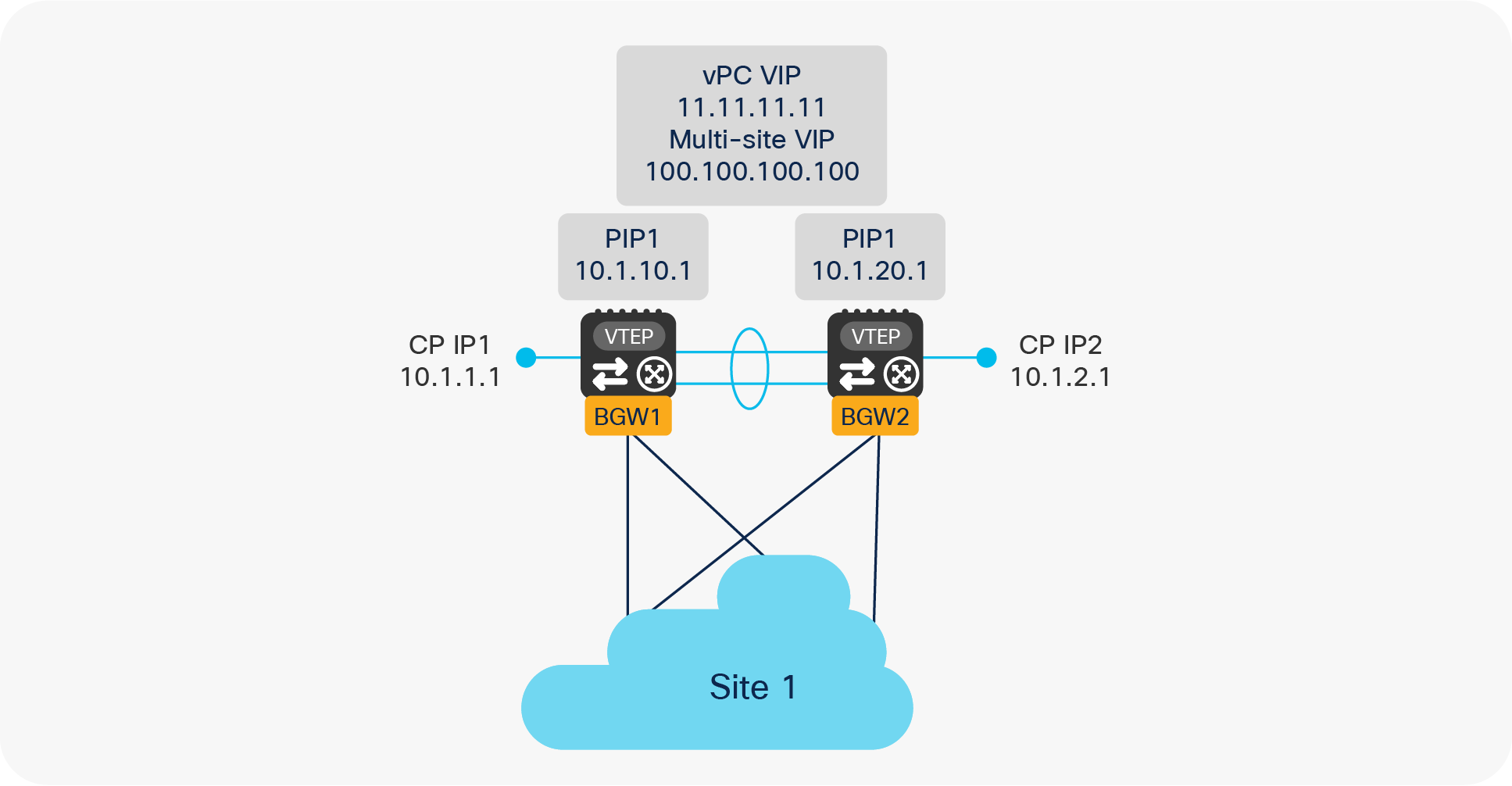
vPC BGW logical interfaces
● Control Plane IP address (CP IP): This is a unique IP address defined on each BGW node and used to establish control plane adjacencies for the MP-BGP EVPN overlay with the remote BGW devices. This IP address is not used for sending or receiving VXLAN encapsulated traffic and acts as Router ID (RID) for the underlay routing protocol.
● Primary IP address (PIP): This is a unique IP address defined on each BGW node and used to source traffic originated by devices that are connected to the BGW via Layer 3 connections and to receive traffic originated from remote sites and destined to those same entities. This would be the case, for example, when the BGW nodes also perform a border leaf role to provide north-south connectivity with the external Layer 3 domain. Use of the Primary IP address has to be activated by configuring “advertise-pip.”
● vPC Virtual IP address (vPC VIP): This is the secondary IP address commonly defined on both BGW nodes part of the same vPC domain and used for two purposes:
1. Sourcing BUM traffic for Layer 2 networks stretched to remote site(s).
2. Sourcing/receiving traffic for single- or dual-attached endpoints locally connected at Layer 2 to the BGWs (Figure 24).
Use of vPC VIP address to source and receive traffic on a vPC BGW node
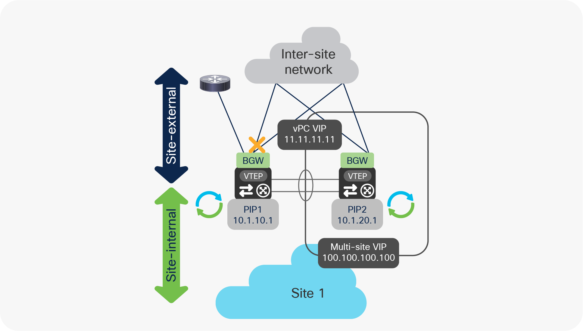
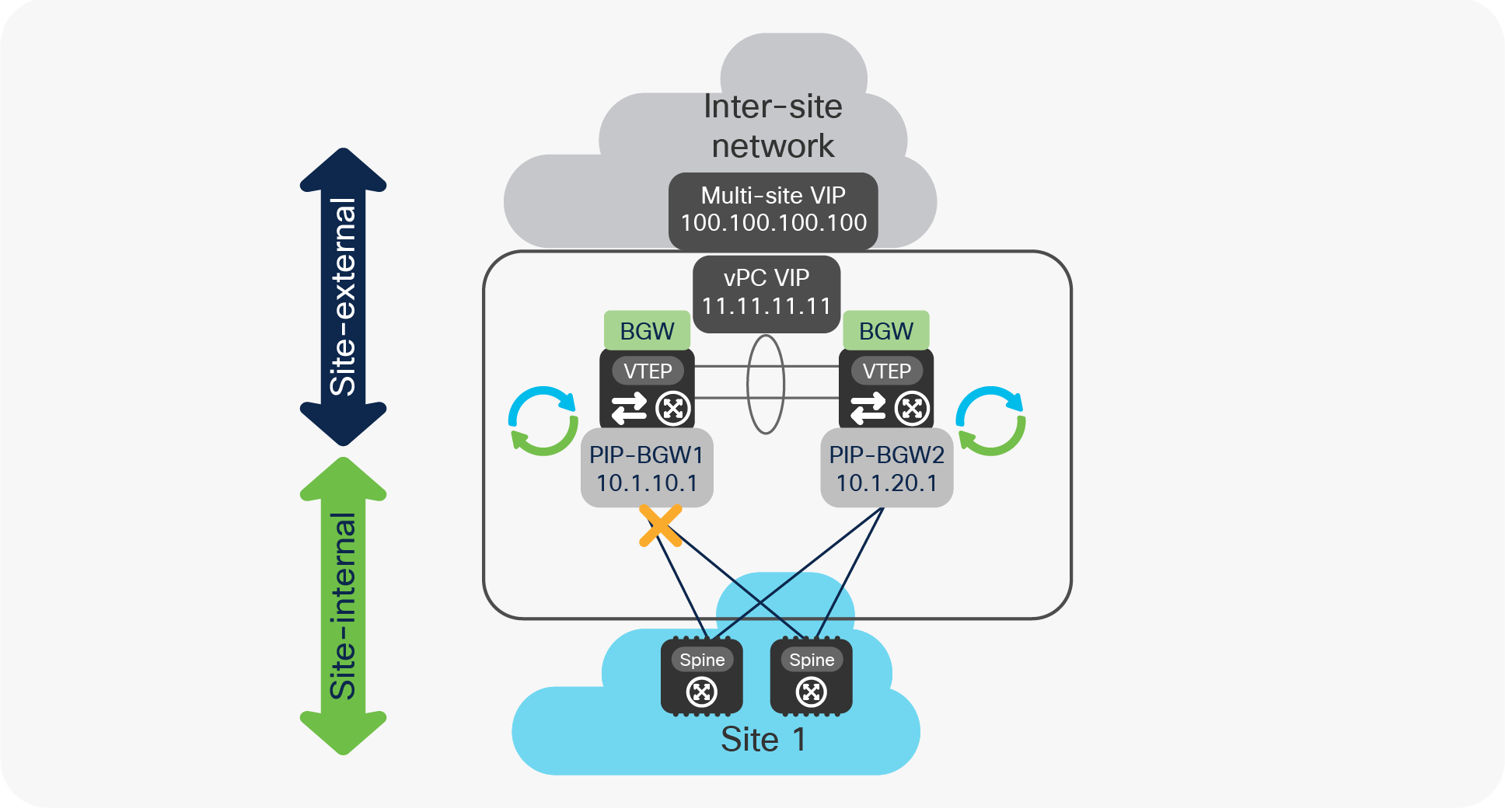
● Multi-Site Virtual IP address (Multi-Site VIP): This is an IP address on a dedicated loopback commonly defined on both BGW nodes that are part of the same vPC domain. This IP address is used to source traffic destined to remote sites and originated from endpoints connected behind a leaf node in the local site. The same IP address is also used to receive traffic originating from remote sites and destined to endpoints connected behind a leaf node in the local site (Figure 25).
Use of Multi-Site VIP address to source and receive traffic on a vPC BGW node
The sample below shows the configuration of those loopback addresses required on a VPC BGW node.
| interface loopback0 description CP IP or RID ip address 10.1.1.1/32 tag 54321 ! interface loopback1 description PIP1 ip address 10.1.10.1/32 tag 54321 ip address 11.11.11.11/32 secondary tag 54321 ! interface loopback100 description Multi-Site VIP1 ip address 100.100.100.100/32 tag 54321 ! interface nve1 host-reachability protocol bgp source-interface loopback1 multisite border-gateway interface loopback100 |
As noticed above, the defined loopback interfaces used to assign the PIP, vPC VIP, and Multi-Site VIP must be specified under the configuration of the logical NVE interface, as an indication that those IP addresses should be used for VXLAN data-plane traffic in the different scenarios previously described.
Note: The use of the “tag 54321” command facilitates the redistribution of the loopback prefixes into the underlay control plane protocol used between sites, as it was discussed in greater detail in the “Migrating legacy data centers to VXLAN EVPN fabrics using vPC BGWs” section in the main text.
EVPN Multi-Site vPC BGW failure scenarios
Since the vPC BGWs represent the interface of a data center network toward the other interconnected sites, it is quite important to understand how failure scenarios are treated by the vPC BGW.
For this purpose, we should distinguish between failures in the transport network that provides reachability between the vPC BGWs at different sites (referred to as the site-external network) and failures in the network internal to the site that provides connectivity to the local VTEP nodes (referred to as site-internal network).
Interface tracking is the mechanism implemented on each BGW node to detect a potential loss of connectivity toward the site-internal or site-external network, and thus be able to properly react to those events and, when necessary, remove the isolated node from the traffic data-path to avoid potential traffic black-holing.
The sample below shows the required configuration to enable the monitoring of the vPC BGW interfaces.
| interface Ethernet1/1 description L3 Link to Site-External Network ip address 10.111.111.1/30 evpn multisite dci-tracking ! interface Ethernet1/2 description L3 Link to Site-Internal Network ip address 10.0.1.5/30 evpn multisite fabric-tracking |
Note: There is no need to track the status of the vPC peer-link connection established between the two BGW nodes part of the same vPC domain.
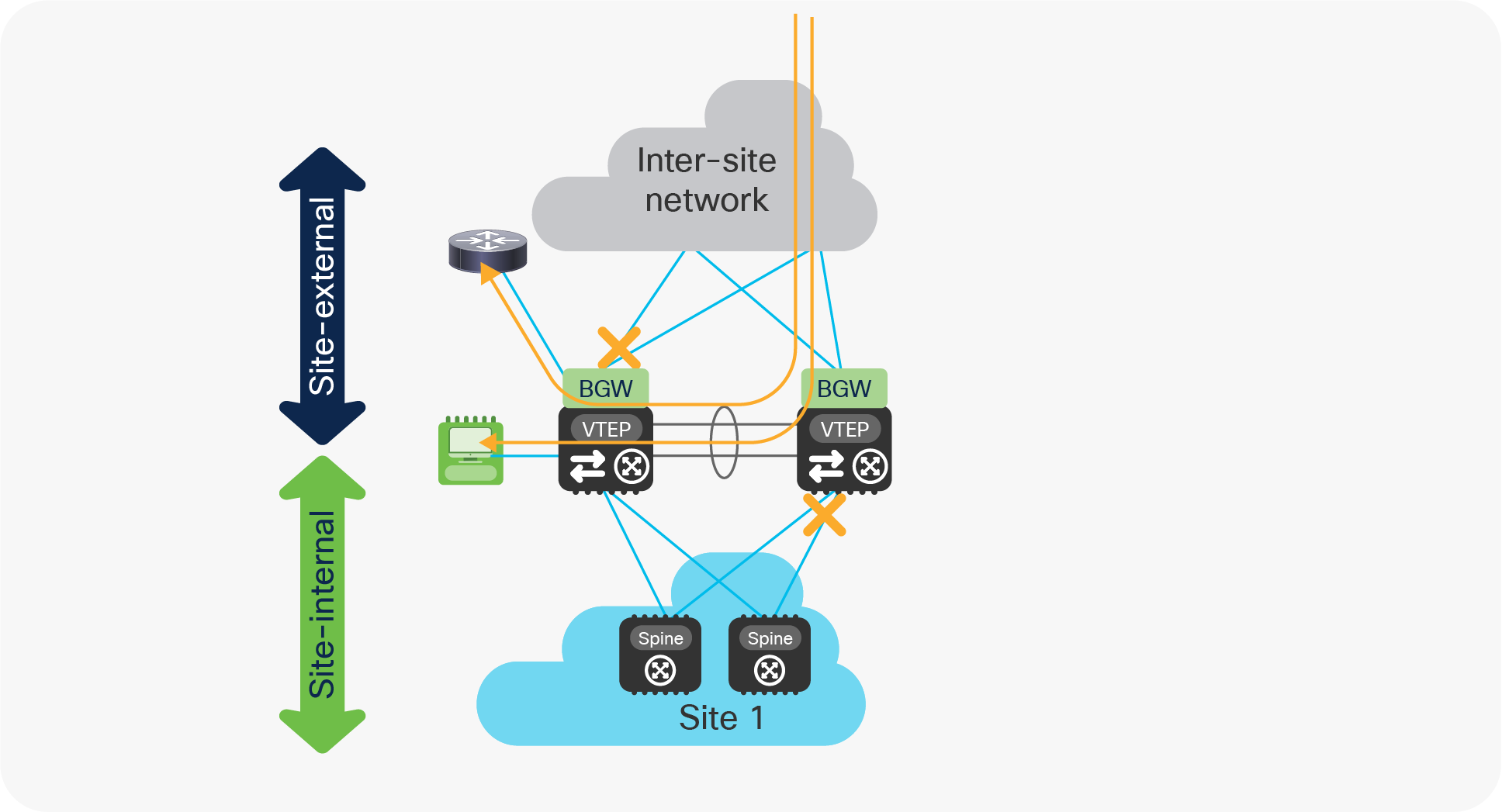
vPC BGW isolation from the site-external network
Figure 26 highlights the specific failure scenario where a vPC BGW node loses all the physical connections toward the site-external network.
vPC BGW isolation from the site-external network
Under those circumstances, the following sequence of events will happen on the vPC BGW node isolated from the site-external network:
● The PIP1 and vPC VIP addresses continue to be advertised toward the site-internal network and to the peer BGW via the Layer 3 adjacency established on the vPC peer-link. This is required to allow connectivity to the external network and to local endpoints (only reachable via the isolated BGW node) both from endpoints connected to the local site and in remote sites.
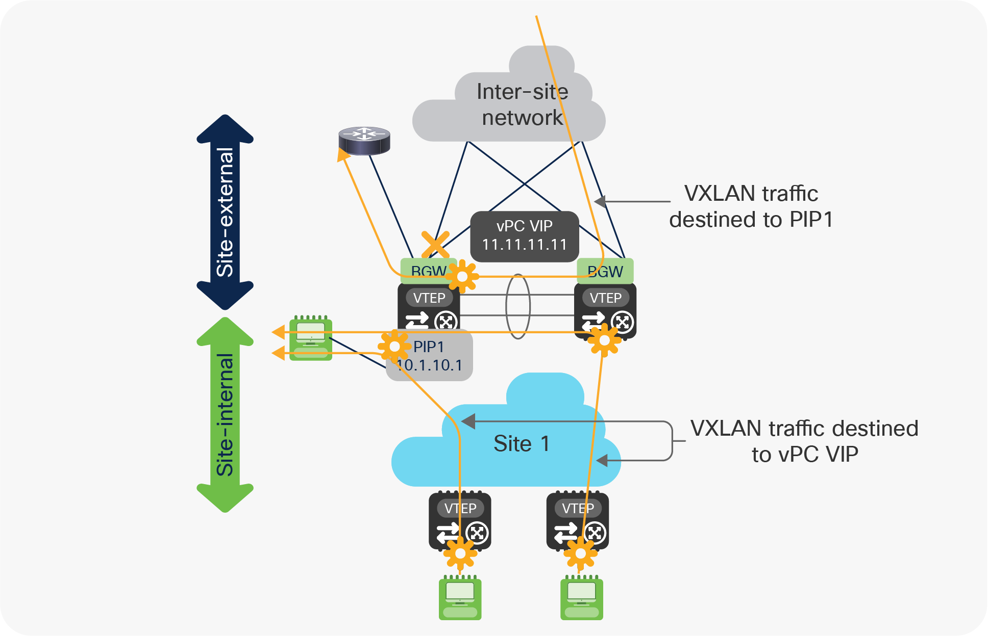
Use of PIP and vPC VIP addresses on the isolated BGW node
As highlighted in Figure 27, a significant amount of traffic may start using the vPC peer-link when a vPC BGW node gets isolated from the site-external network. It is therefore important to properly dimension the bandwidth available on the peer-link to be able to support this additional traffic.
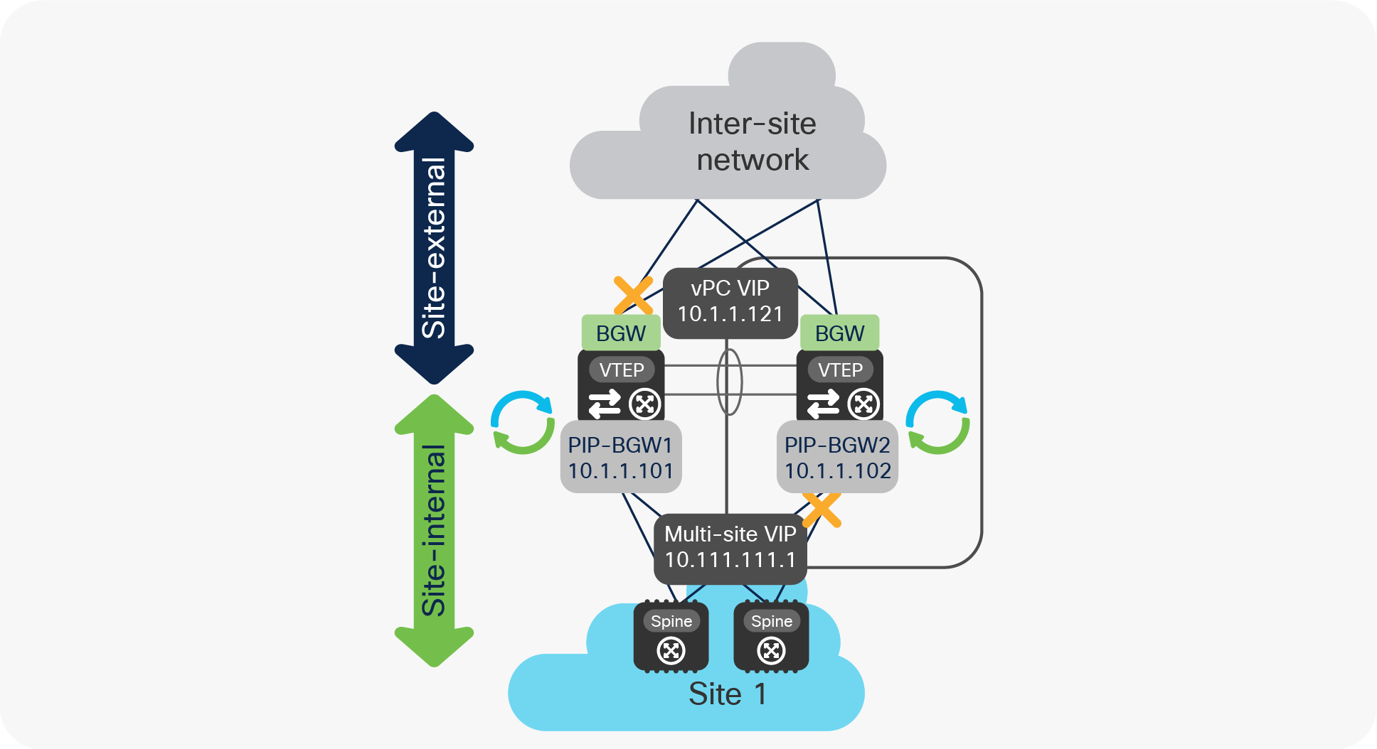
● The Multi-Site VIP address stops being advertised toward the site-internal network. This ensures that traffic originating from endpoints connected to local leaf nodes and destined to remote sites (and vice versa) can be steered directly to the vPC BGW node still connected to the site-external network (there is no need to use the vPC peer-link connection in this case).
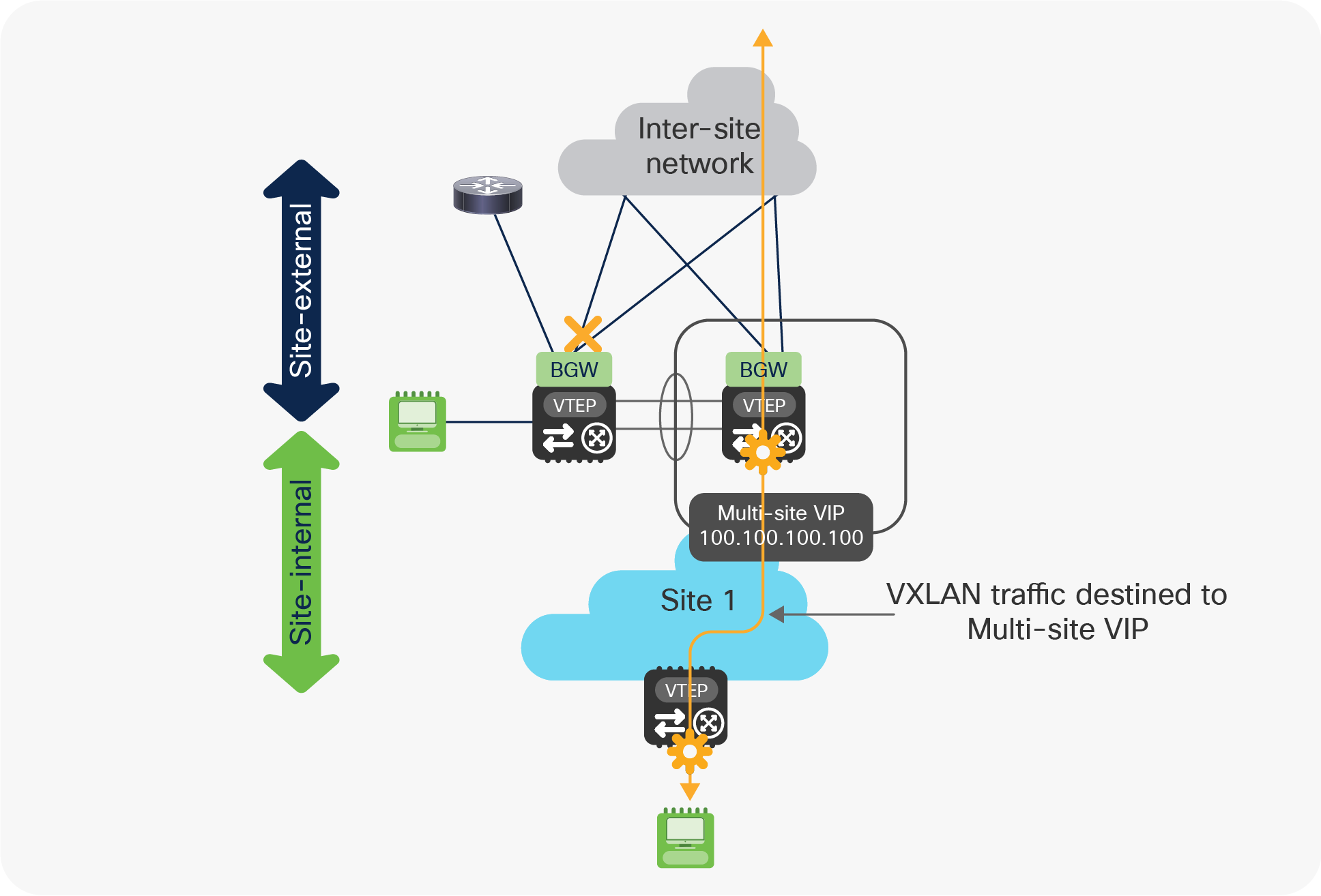
Use of Multi-Site VIP only on the vPC BGW still connected to the site-external network
It is worth noticing that the Multi-Site VIP stops being advertised as the associated loopback interface gets dynamically administratively shut down on the BGW node once the isolation condition from the site-external network is detected.
● Once at least one of the connections toward the site-external network is recovered, the BGW node can start re-establishing the direct underlay peering with the site-external network. The Multi-Site VIP loopback interface will remain in a down state for a configurable time (the default value is 300 seconds).
vPC BGW isolation from the site-internal network
Figure 29 highlights the specific failure scenario where a vPC BGW node loses all the physical connections toward the site-internal network.
vPC BGW isolation from the site-internal network
Under those circumstances, all the logical interfaces on the isolated BGW (PIP, vPC VIP, and Multi-Site VIP) remain active and their addresses are still advertised toward the site-external network (and to the peer BGW via the Layer 3 adjacency established on the vPC peer-link).
This implies that 50 percent of the traffic flows incoming from remote sites will need to be forwarded via the vPC peer-link, together with the totality of flows originated from endpoints or networks directly connected to the isolated BGW node (Figure 30).
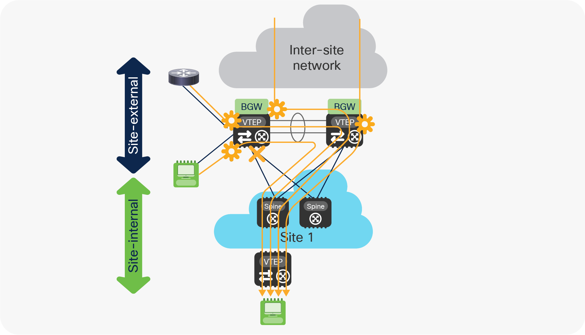
Use of PIP, vPC VIP, and Multi-Site VIP on the isolated BGW node
As previously mentioned, it becomes critical to properly size the bandwidth available on the vPC peer-link connection to account for those additional traffic flows.
Once the first link to the site-internal network recovers, the BGW node re-establishes underlay connectivity with the spines and starts sending and receiving traffic in a more optimized way without use anymore of the peer-link.
The behaviors described in the previous two sections also allow handling of the very specific “zig-zag” isolation scenario shown in Figure 31, where the vPC BGW nodes experience simultaneous failures that cause isolation from the site-internal and site-external networks.
“Zig-zag” isolation scenario
The fact that the Multi-Site VIP interface remains active on the BGW node isolated from the site-internal network still allows incoming traffic originated from the remote sites to be forwarded to the local site via the peer-link connection (and vice versa), as highlighted in Figure 32.
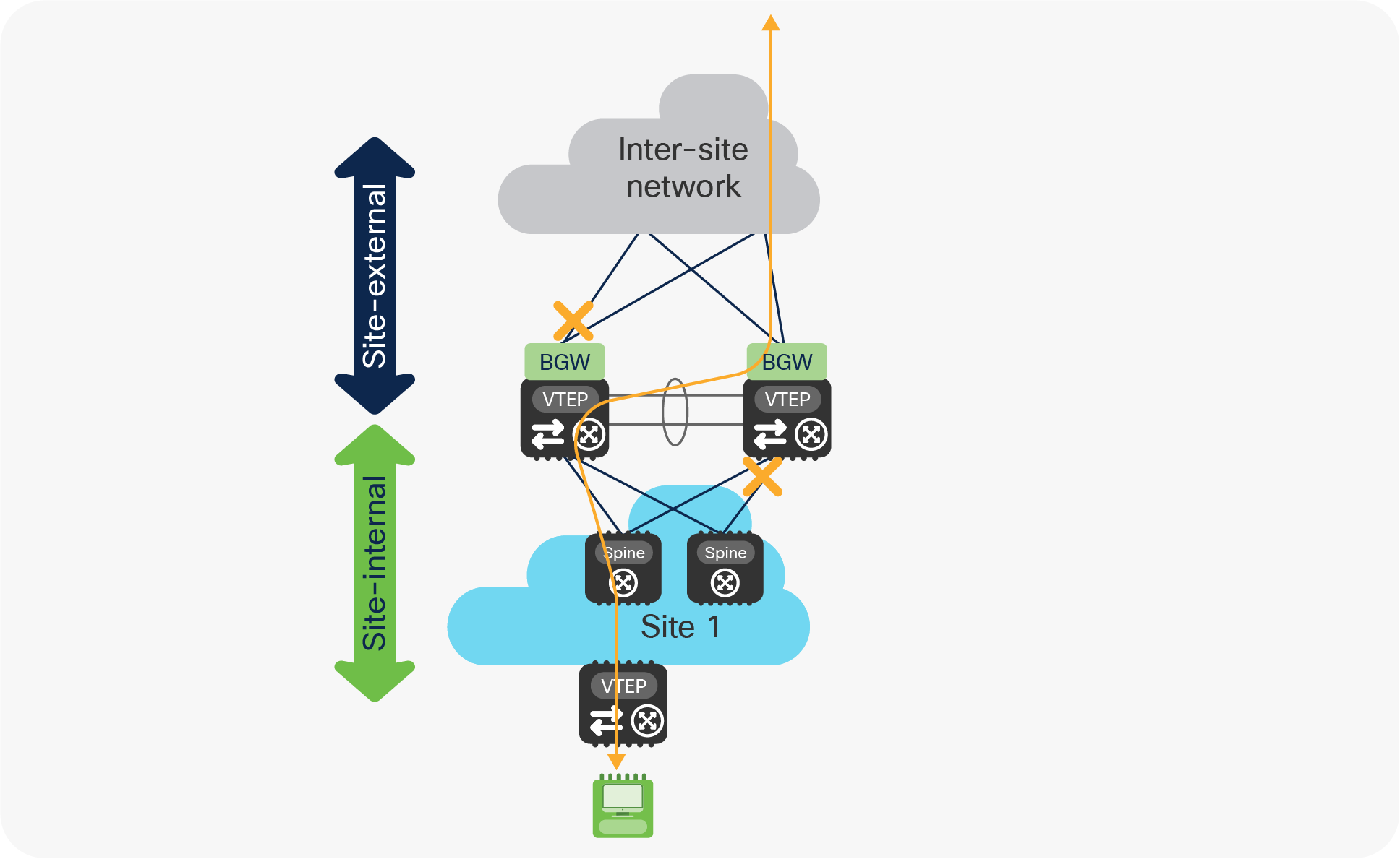
“Zig-zag” traffic behavior
The vPC peer-link can also be utilized to forward incoming traffic originating from remote sites and destined to endpoints and networks locally connected to the BGW node on the left in the figure above (isolated from the site-external network), which leads to the usual considerations about the need to properly dimension it.
Incoming traffic destined to entities locally connected to the BGW node