Migrating Cisco FabricPath Environments to VXLAN BGP EVPN White Paper
Available Languages
Bias-Free Language
The documentation set for this product strives to use bias-free language. For the purposes of this documentation set, bias-free is defined as language that does not imply discrimination based on age, disability, gender, racial identity, ethnic identity, sexual orientation, socioeconomic status, and intersectionality. Exceptions may be present in the documentation due to language that is hardcoded in the user interfaces of the product software, language used based on RFP documentation, or language that is used by a referenced third-party product. Learn more about how Cisco is using Inclusive Language.
- US/Canada 800-553-2447
- Worldwide Support Phone Numbers
- All Tools
 Feedback
 Feedback
This document describes how to achieve migration from a Cisco FabricPath ”brownfield” environment to a ”greenfield” virtual extensible LAN (VXLAN) Border Gateway Protocol (BGP) Ethernet Virtual Private Network (EVPN) fabric. The main focus here is how the Cisco FabricPath network can be extended to a VXLAN BGP EVPN fabric, including migration of the first-hop gateway, which in turn facilitates moving workloads from the old network to a new one. The migration use case includes the connectivity to an external Layer 3 network.
The scope of this document is to specifically cover the concepts for interconnecting a Cisco FabricPath brownfield environment with a new VXLAN BGP EVPN fabric.
Limited background information is included on other related components whose understanding is required for the migration. (See the “For more information” section at the end of this document for where to find background information on VXLAN BGP EVPN and Cisco FabricPath.)
Note: The documentation set for this product strives to use bias-free language. For the purposes of this documentation set, bias-free is defined as language that does not imply discrimination based on age, disability, gender, racial identity, ethnic identity, sexual orientation, socioeconomic status, and intersectionality. Exceptions may be present in the documentation due to language that is hardcoded in the user interfaces of the product software, language used based on RFP documentation, or language that is used by a referenced third-party product.
Migrating a Brownfield Network
The specific migration process described in this document is usually referred to as “Virtual Port Channel (VPC) back-to-back” and consists of interconnecting an existing brownfield network (based on Spanning Tree Protocol, VPC, or FabricPath technologies) to a newly developed VXLAN BGP EVPN fabric, with the end goal of migrating applications or workloads between those environments.
Figure 1 shows the migration methodology, which highlights the major steps required for performing the migration of applications.
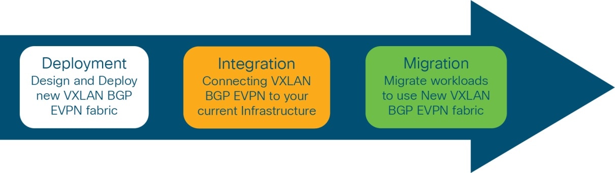
Migration steps
The steps of the migration methodology are as follows:
1. First is the design and deployment of the new VXLAN BGP EVPN environment (greenfield network). It is likely that such a deployment will initially be small, with plans to grow over time as the number of workloads go up. A typical VXLAN BGP EVPN fabric consists traditionally of a leaf-and-spine topology.
2. Second is the integration between the existing data center network infrastructure (usually called the brownfield network) and the new VXLAN BGP EVPN fabric. Layer 2 and Layer 3 connectivity between the two networks is required for successful application and workload migration across the two network infrastructures.
3. The final step consists of migrating workloads between the brownfield and the greenfield network. It is likely that this application migration process will take several months to complete, depending on the number and complexity of the applications being migrated. The communication between the greenfield and brownfield networks, across the Layer 2 and Layer 3 connections established in step 2, are used during this phase.
Through the migration steps, the placement of the first-hop gateway needs to be carefully considered. For newly deployed Virtual LANs (VLANs) and associated IP subnets, the greenfield network is the desired place for hosting the first-hop gateway function.
For VLANs and associated IP subnets that are migrated from the brownfield to the greenfield network, the timing of the first-hop gateway migration can be chosen based on the following criteria:
● When the majority of the workloads are migrated to the greenfield network
● Premigration of the first workload
● Postmigration of the last workload
The correct timing depends on many factors, with the most critical being when a disruption to the network can be accommodated.
Interconnecting the brownfield network with the greenfield network via Layer 2 is crucial to facilitate seamless workload migration.
Note: In cases where seamless workload migration is not required, a Layer 2 interconnect between brownfield and greenfield is not necessary. In these cases, a per-VLAN or per-IP subnet approach can be chosen for the migration. This approach does not provide a seamless migration, but it is viable if it is otherwise deemed beneficial.
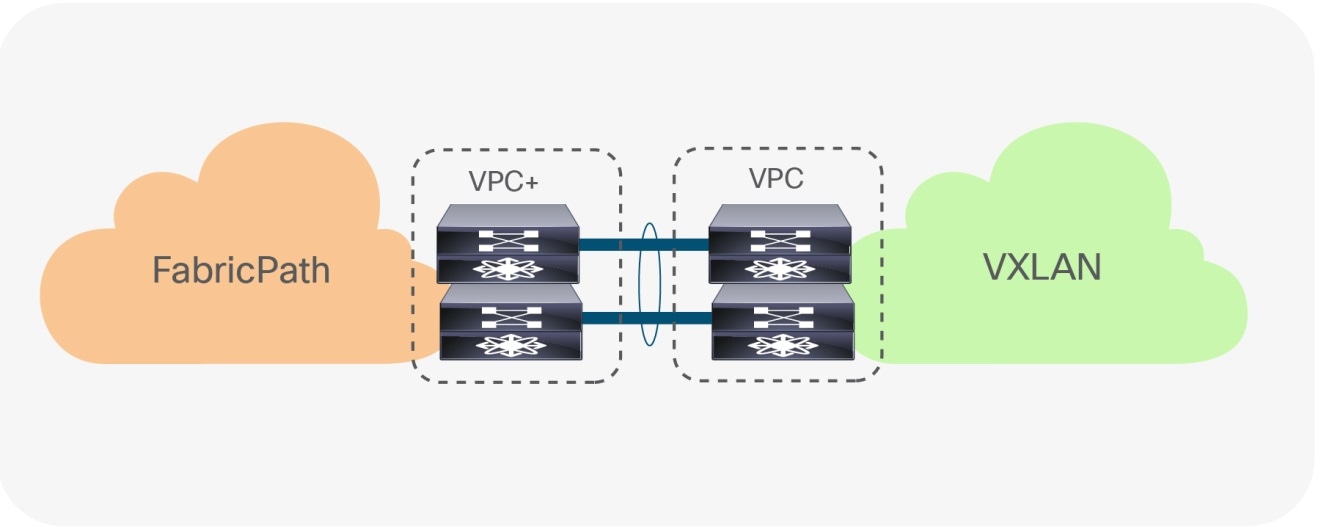
Figure 2 shows the brownfield-greenfield interconnection, which highlights the major components of the migration approach.
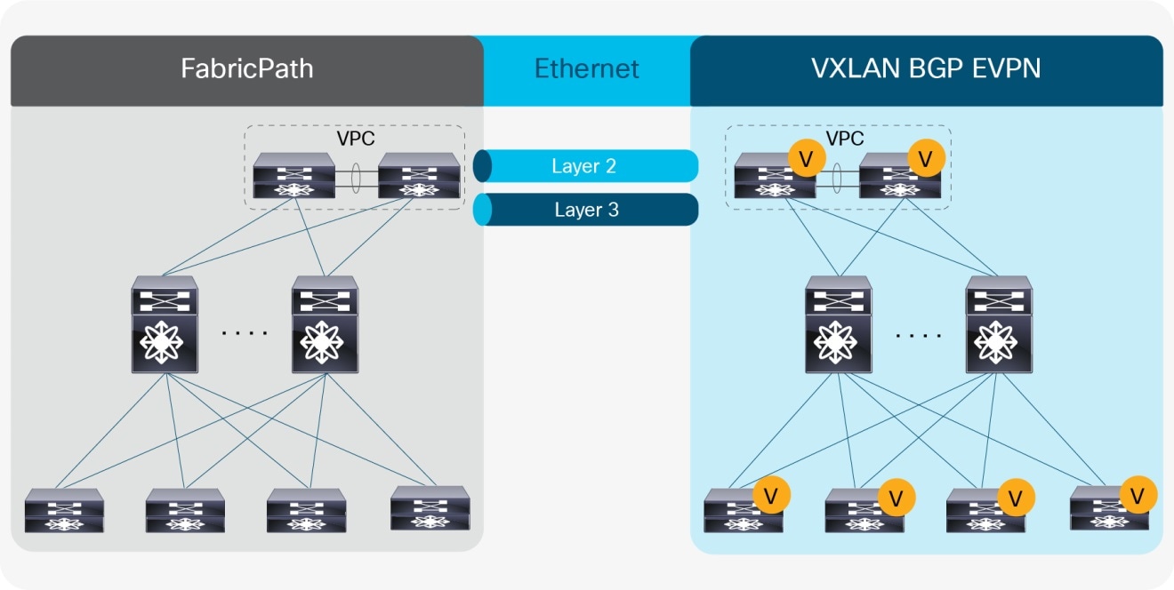
Overview: Brownfield-Greenfield Interconnection
For the Layer 2 interconnection, we establish a double-sided VPC+ (Virtual Port-Channel for FabricPath) between a pair of nodes in the greenfield (VXLAN) and brownfield (FabricPath) networks. As the focus of the migration is from a Cisco FabricPath network, we interconnect the VPC+ domain with the VPC domain in the VXLAN BGP EVPN fabric. The double-sided VPC+ connection between the two network infrastructures allows a Layer 2 extension without risking any Layer 2 loop by maintaining all VPC links for actively forwarding traffic.
The nodes chosen in the greenfield network can represent a border node or any other switch that provides the VXLAN BGP EVPN tunnel endpoint functionality. In the brownfield network, the nodes for the interconnection should represent the Layer 2–Layer 3 demarcation. In the case of Cisco FabricPath, the Layer 2–Layer 3 demarcation is found at various locations, depending on the topology and first-hop gateway mode that is chosen. The commonly found Cisco FabricPath deployments are as follows:
● Access-aggregation with first-hop gateway at aggregation using VPC and traditional First Hop Routing Protocol (FHRP), that is, Hot Standby Router Protocol (HSRP)
● Leaf-and-spine with first-hop gateway at leaf using VPC and traditional FHRP (HSRP)
● Leaf-and-spine with first-hop gateway at spine (anycast HSRP)
Figures 3–5 depict these topologies and associated gateway placement options for the brownfield network.
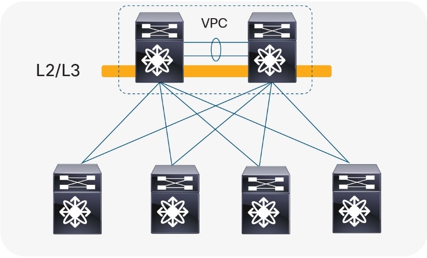
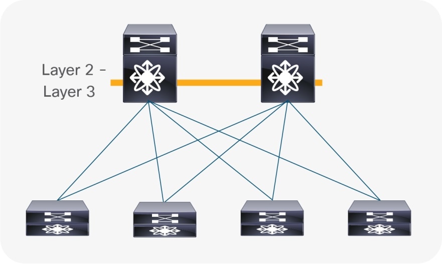
Access-Aggregation with First-Hop Gateway at Aggregation
The access-aggregation topology with Cisco FabricPath shown in Figure 3, would look identical to a brownfield network that was built with Spanning Tree Protocol or VPC technology. The difference is solely in the use of the FabricPath encapsulation, which also enables an Equal-Cost Multipathing (ECMP) Layer 2 network without the need for Spanning Tree Protocol or VPC. The reason for leveraging VPC+ between the aggregation nodes is to achieve active-active forwarding for the first-hop gateway function. VPC+ paired with HSRP or VRRP allows active-active forwarding while HSRP or Virtual Router Redundancy Protocol (VRRP) alone would allow only a single-active node.
The Layer 2–Layer 3 interconnection between the brownfield and the greenfield network would be placed at the aggregation nodes.
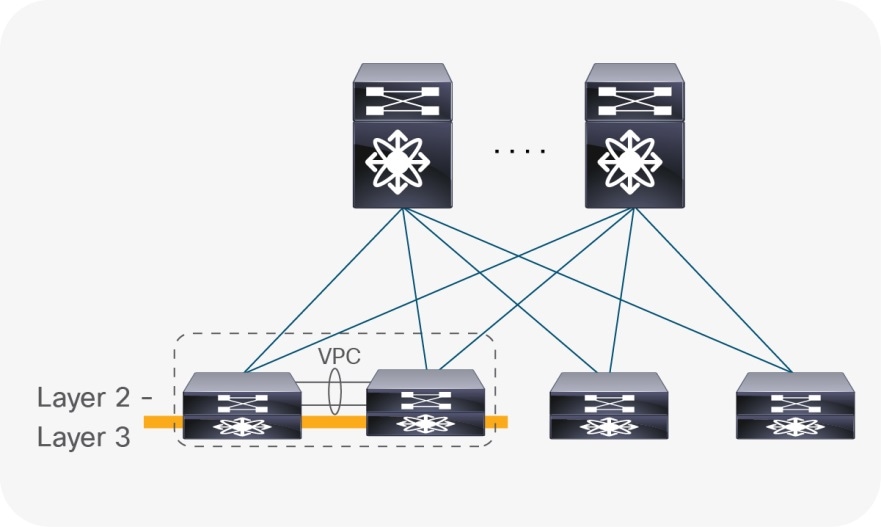
Leaf-and-Spine with First-Hop Gateway at Leaf
Similar to the access-aggregation topology, the protocol and encapsulation used between the leaf and spine layer is FabricPath, for the topology shown in Figure 4. In this specific topology, no endpoints or external connectivity are present at the spine, the number of FabricPath nodes at the spine location is not limited through VPC+ or FHRP, and the topology can be scaled out. The first-hop gateway function is placed at the leaf layer, which we recommend be a dedicated pair of FabricPath nodes for the first-hop gateway and external connectivity (hence also called border nodes). As before, VPC+, coupled with HSRP or VRRP, provides active-active forwarding for the first-hop gateway function. The use of a dedicated node pair for the first-hop gateway is recommended but not required. In some deployments, different leaf pairs may host first-hop gateways for different Virtual LANs (VLANs) and associated IP subnets with an appropriate routing protocol advertising the subnet prefixes between these gateway hosting nodes, thereby allowing any-to-any connectivity. One of these leaf pairs can be chosen to serve as border nodes.
The Layer 2–Layer 3 interconnect between the brownfield and the greenfield network would be placed at the border nodes.
Leaf-and-Spine with First-Hop Gateway at Spine (Anycast HSRP)
With anycast HSRP deployments (see Figure 5), again the leaf-and-spine topology is deployed with FabricPath. The number of FabricPath nodes at the spine is limited only by the choice of the first-hop gateway approach in this deployment. With FabricPath, a four-way all-active first-hop gateway approach exists with the usage of anycast HSRP. The first-hop gateway is not required to be placed at the spine, but this is likely to be the most common deployment with anycast HSRP. In the scenario where no VPC+ is present at the spine, the Layer 2–Layer 3 interconnection between the brownfield network and the greenfield network will be achieved at different nodes. While the Layer 3 connectivity must be at the spine nodes co-located with the first-hop gateway, the Layer 2 interconnection can be anywhere at a VPC+ domain.
Note: With anycast HSRP at the spine layer, VPC+ is not required to achieve active-active first-hop gateway forwarding. Consequently, for these kinds of deployments, VPC+ cannot be assumed to be present at the spine layer.
VPC Considerations
VPC is typically used in the access or aggregation layer of a network. At the access layer, it is used for active-active connectivity from endpoints (server, switch, NAS storage device, etc.) to the VPC domain. At the aggregation layer, VPC is used for providing both active-active connectivity from access layer to the aggregation VPC domain, and active-active connectivity to the first-hop gateway in conjunction with HSRP or VRRP, for the Layer 2–Layer 3 demarcation.
However, because VPC provides capabilities to build a loop-free topology, it is also commonly used to interconnect two separate networks at Layer 2, allowing extension of the Layer 2 domain. For the scope of this document, VPC (or more specifically VPC+) is used to interconnect the brownfield Cisco FabricPath network with the greenfield VXLAN BGP EVPN network.
Double-sided VPC (Loop-Free Topology)
Note: Using VPC and VPC+ for Layer 2 interconnection between the brownfield and greenfield networks makes all existing VPC best practices applicable.
VPC Configuration
The configuration examples provided in this section highlight key concepts for interconnecting the brownfield and greenfield networks.
FabricPath VPC+
The configuration example below shows a Cisco FabricPath VPC+ domain in a brownfield network. The individual FabricPath switch-IDs are 21 and 22, for nodes 1 and 2, respectively, and the emulated switch-ID is 200, shared across the two FabricPath switches. Port-Channel 1 comprising member ports Ethernet 1/47 and 1/48, represents the VPC+ peer-link, which is required to be a FabricPath core port (switchport mode fabricpath). In addition, a Port-Channel 20 with VPC ID 20 is configured to provide Layer 2 interconnection to the VXLAN BGP EVPN greenfield network. The Virtual Port-Channel 20 has Ethernet interface 1/1 as a member port for the IEEE 802.1Q trunk and uses Link Aggregation Control Protocol (LACP).
Note: With LACP, the VPC domain ID should be different in the brownfield and greenfield networks.
FabricPath Node 1
fabricpath switch-id 21
!
vpc domain 20
fabricpath switch-id 200
!
interface port-channel 1
description VPC+ peer-link
switchport mode fabricpath
vpc peer-link
!
interface port-channel 20
description virtual port-channel to greenfield
switchport mode trunk
vpc 20
!
interface Ethernet 1/1
description member port of port-channel/VPC 20
switchport mode trunk
channel-group 20 mode active
!
interface ethernet 1/47
description member port VPC+ peer-link
switchport mode fabricpath
channel-group 1
!
interface ethernet 1/48
description member port VPC+ peer-link
switchport mode fabricpath
channel-group 1
FabricPath Node 2
fabricpath switch-id 22
!
vpc domain 20
fabricpath switch-id 200
!
interface port-channel 1
description VPC+ peer-link
switchport mode fabricpath
vpc peer-link
!
interface port-channel 20
description virtual port-channel to greenfield
switchport mode trunk
vpc 20
!
interface Ethernet 1/1
description member port of port-channel/VPC 10
switchport mode trunk
channel-group 10 mode active
!
interface ethernet 1/47
description member port VPC+ peer-link
switchport mode fabricpath
channel-group 1
!
interface ethernet 1/48
description Member port VPC+ peer-link
switchport mode fabricpath
channel-group 1
VXLAN BGP EVPN VPC
The configuration example below shows a Cisco VXLAN BGP EVPN VPC domain in the greenfield network. The individual VXLAN tunnel endpoint (VTEP) IP addresses are 10.10.10.11 and 10.10.10.12, for nodes 1 and 2, respectively, and the anycast VTEP IP address is 10.10.10.100, shared across both nodes. Port-channel 1 represents the VPC peer-link, which is a traditional IEEE 802.1Q trunk (switchport mode trunk) with participating interfaces Ethernet 1/47 and 1/48. In addition, a port-channel with VPC ID 10 is configured to provide the Layer 2 interconnection to the brownfield FabricPath network. The virtual port-channel 10 has interface Ethernet 1/1 as a member port for the IEEE 802.1Q trunk and uses LACP.
Note: With LACP, the VPC domain ID should be different in the brownfield and greenfield network.
VXLAN BGP EVPN Node 1
vpc domain 10
peer-switch
peer-gateway
ipv6 nd synchronize
ip arp synchronize
!
interface loopback1
description loopback for VTEP (NVE)
ip address 10.10.10.11/32
ip address 10.10.10.100/32 secondary
!
interface port-channel 1
description VPC peer-link
switchport mode trunk
vpc peer-link
!
interface port-channel 10
description virtual port-channel to brownfield
switchport mode trunk
vpc 10
!
interface Ethernet 1/1
description member port of port-channel/VPC 10
switchport mode trunk
channel-group 10 mode active
!
interface ethernet 1/47
description member port VPC peer-link
switchport mode trunk
channel-group 1
!
interface ethernet 1/48
description member port VPC peer-link
switchport mode trunk
channel-group 1
VXLAN BGP EVPN node 2
vpc domain 10
peer-switch
peer-gateway
ipv6 nd synchronize
ip arp synchronize
!
interface loopback1
description loopback for VTEP (NVE)
ip address 10.10.10.12/32
ip address 10.10.10.100/32 secondary
!
interface port-channel 1
description VPC peer-link
switchport mode trunk
vpc peer-link
!
interface port-channel 10
description virtual port-channel to brownfield
switchport mode trunk
vpc 10
!
interface Ethernet 1/1
description member port of port-channel/VPC 10
switchport mode trunk
channel-group 10 mode active
!
interface ethernet 1/47
description member port VPC peer-link
switchport mode trunk
channel-group 1
!
interface ethernet 1/48
description member port VPC peer-link
switchport mode trunk
channel-group 1
Spanning-Tree Considerations
Cisco FabricPath supports not only endpoint connections but also connection of Ethernet networks running Spanning Tree Protocol. Each Cisco FabricPath enabled node must be configured as the Spanning Tree root for all FabricPath VLANs. When an Ethernet switch running Spanning Tree is connected to a Cisco FabricPath network, the entire Cisco FabricPath network will be perceived as a single Spanning Tree node.
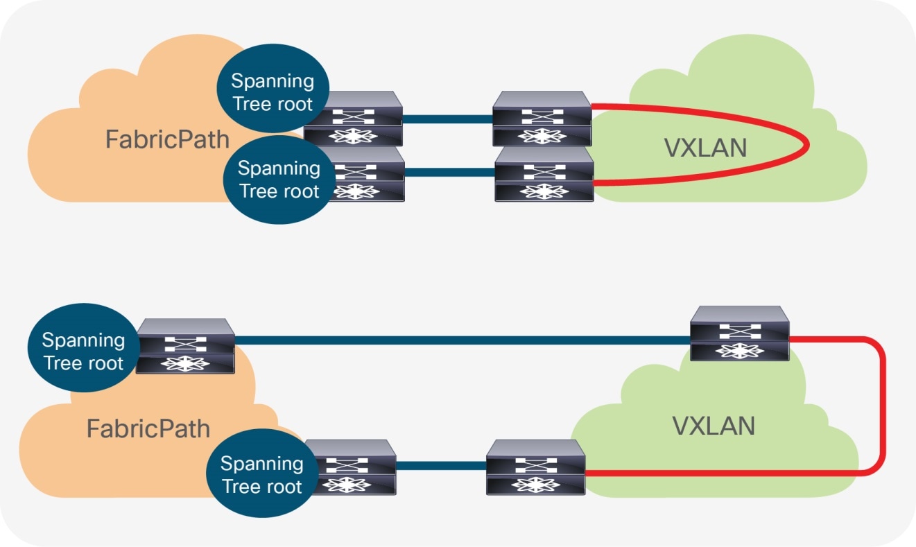
Layer 2 Interconnect with Loop
As opposed to a Cisco FabricPath network, a VXLAN BGP EVPN network has no specific requirement in relation to Spanning Tree. Even as the best practice dictates that every VTEP should be performing as the Spanning Tree root, much as in FabricPath, the VXLAN overlay itself is not aware of Bridge Protocol Data Units (BPDUs) or Spanning Tree–related forwarding state, nor will it forward them. With the Cisco FabricPath network becoming the Spanning Tree root, the connected VTEPs should have the Spanning Tree root port toward the FabricPath network. As a result, it is crucial that only a single, logical or physical, active Layer 2 connection between the brownfield and greenfield network be active. Otherwise, a Layer 2 loop will be present, as shown in Figure 7. The single active connection can be achieved using a double-sided VPC+ connection or by manual VLAN distribution (see Figure 8).
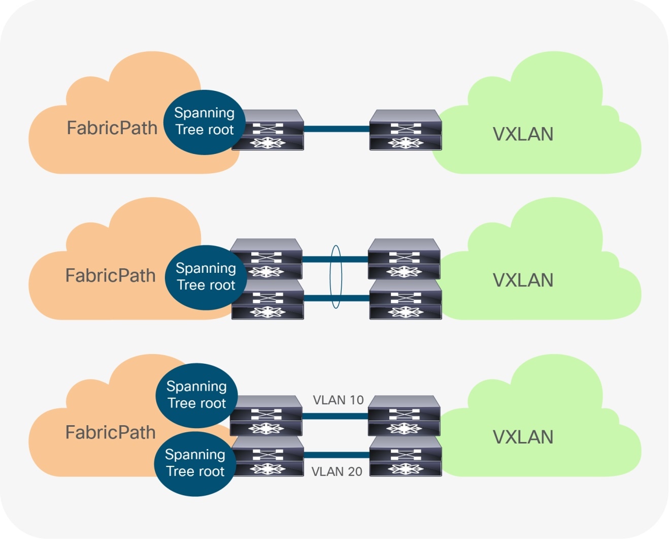
Loop-free Layer 2 interconnect (options)
Note: Spanning Tree BPDUs from the Cisco FabricPath network will be sent towards the VTEPs, but the VXLAN overlay will not forward the BPDUs, nor will it perform any blocking action on the VXLAN tunnel. As a result, a Layer 2 Loop can occur, so proper design of the Layer 2 interconnect is critical.
Spanning Tree Configuration
The examples in this section highlight the key concepts for interconnecting the brownfield and greenfield network as well as the Spanning Tree caveats. All best practices for Spanning Tree with FabricPath VPC+ and VXLAN BGP EVPN VPC are applicable, whether or not they are shown in these examples.
FabricPath Spanning Tree and VPC+
The first example below shows the Spanning Tree and VPC+ configuration of the brownfield network. The individual FabricPath switch-IDs are 21 and 22 for nodes 1 and 2, respectively, and the emulated switch-ID is 200, shared across both FabricPath nodes. The VPC domain ID is 20. The Spanning Tree domain of 20 is chosen to allow Spanning Tree Topology Change Notification (TCN) forwarding between all FabricPath nodes with the same Spanning Tree domain ID. The Spanning Tree pseudo information, as well as the Spanning Tree priority, is set on both nodes to be the same and the lowest value, so that the FabricPath nodes become the Spanning Tree root.
Note: All Cisco FabricPath nodes must have set the same Spanning Tree priority so that they become the root. This allows the complete FabricPath network to represent as a single Spanning Tree bridge-ID, which must be the root. Cisco FabricPath has an implicit root guard configured on all Ethernet interfaces. If a connected Spanning Tree talking node with a superior (lower value) priority is seen, these interfaces will go into blocking state:
2018 Jan 10 19:33:03 FP-SW-21 %STP-2-L2GW_BACKBONE_BLOCK: L2 Gateway Backbone port inconsistency blocking port Ethernet1/1 on VLAN0100.
FabricPath Node 1
fabricpath switch-id 21
!
vpc domain 20
fabricpath switch-id 200
!
spanning-tree domain 20
spanning-tree vlan 1-4094 priority 4096
spanning-tree pseudo-information
vlan 1-4094 root priority 4096
FabricPath Node 2
fabricpath switch-id 22
!
vpc domain 20
fabricpath switch-id 200
!
spanning-tree domain 20
spanning-tree vlan 1-4094 priority 4096
spanning-tree pseudo-information
vlan 1-4094 root priority 4096
VXLAN BGP EVPN Spanning Tree and VPC
The next example shows a Cisco VXLAN BGP EVPN VPC domain in the greenfield network. The individual VTEP IP addresses are 10.10.10.11 and 10.10.10.12, for nodes 1 and 2, respectively, and the anycast VTEP IP address is 10.10.10.100, shared across both VXLAN nodes. The Spanning Tree priority is set on both nodes to be the same and of an inferior value to the FabricPath nodes, so that the FabricPath nodes remain the Spanning Tree root.
Note: The VXLAN Overlay does not forward BPDUs, hence no Spanning Tree blocking ports exist, specifically for the overlay. Best practice dictates setting the lowest Spanning Tree priority (root) on all the VXLAN BGP EVPN nodes, but as the Cisco FabricPath network needs to be root, this practice has to be changed for the migration.
VXLAN BGP EVPN Node 1
vpc domain 10
peer-switch
peer-gateway
ipv6 nd synchronize
ip arp synchronize
!
interface loopback1
description loopback for VTEP (NVE)
ip address 10.10.10.11/32
ip address 10.10.10.100/32 secondary
!
spanning-tree vlan 1-4094 priority 32768
VXLAN BGP EVPN Node 2
vpc domain 10
peer-switch
peer-gateway
ipv6 nd synchronize
ip arp synchronize
!
interface loopback1
description loopback for VTEP (NVE)
ip address 10.10.10.12/32
ip address 10.10.10.100/32 secondary
!
spanning-tree vlan 1-4094 priority 32768
Note: Spanning Tree root is specific to the Cisco Nexus 7000 Series Switches implementation. As this is a mismatch to the requirement for interconnecting with a Cisco FabricPath network, a BPDU filter must be used on the Layer 2 interconnecting interfaces. Alternate methods are valid as long as the requirement for Spanning Tree root on the FabricPath and VXLAN side is met.
VLAN Mapping
In Cisco FabricPath, with or without VPC+, all VLANs must be set in fabricpath mode to allow the respective Layer 2 traffic to be forwarded from one FabricPath enabled node to another. Primarily, Cisco FabricPath uses the traditional 12-bit VLAN namespace (Figure 9), which allows for approximately 4000 VLANs.
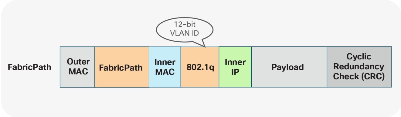
FabricPath Namespace
Regardless of the VLAN mode, as soon as traffic exits an Ethernet port, traditional Ethernet and VLAN semantics are used (Figure 10). Multiple FabricPath enabled VLANs can be transported over a single IEEE 802.1Q trunk toward an endpoint or Ethernet switch.
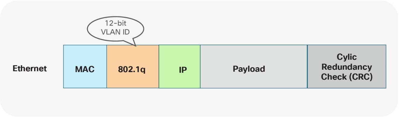
Ethernet Namespace
With VXLAN, with or without VPC, VLANs do not exist between the VTEPs themselves. Instead of using the VLAN namespace within a VXLAN enabled fabric, mapping is done on the nodes performing the VTEP function. At the VTEP, the Ethernet VLAN identifier is mapped to a VXLAN Network Identifier (VNI) through configuration. As a result, the VLAN itself becomes locally significant to the VTEP, whereas when communication is transported between VTEPs, a different namespace is used. VXLAN provides a more extensive namespace by allowing approximately 16 million unique identifiers in its 24-bit namespace (Figure 11).
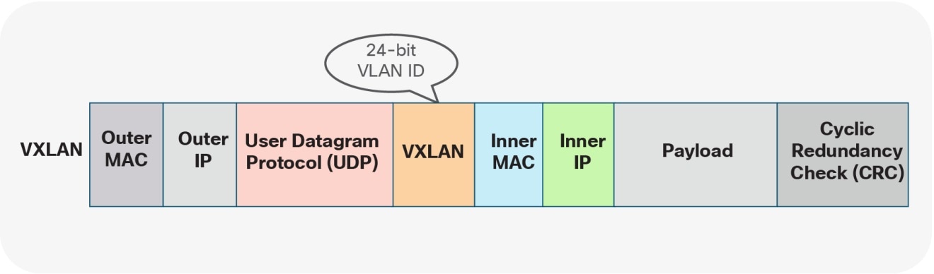
VXLAN Namespace
Given these different approaches taken by the Cisco FabricPath and the VXLAN BGP EVPN fabrics, the VLAN mapping is not required to be consistent across all the network nodes in either the brownfield or greenfield network.
The following two scenarios show the different VLAN-mapping approaches available for the Cisco FabricPath to VXLAN BGP EVPN migration.
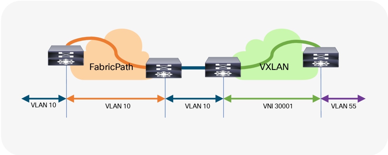
Scenario 1: 1:1 Mapping Between VLANs
The first scenario follows a consistent mapping where all the VLANs on every Ethernet-enabled node are consistent. This means that from the very first FabricPath node (ingress), the VLAN will stay consistent until it reaches the first VTEP (ingress). At this point, the VLAN will be mapped to a VNI and transported across the overlay. At the destination VTEP (egress), the VNI is mapped to the same originally used VLAN. This scenario is referred to as 1:1 mapping or consistent VLAN usage (Figure 12).
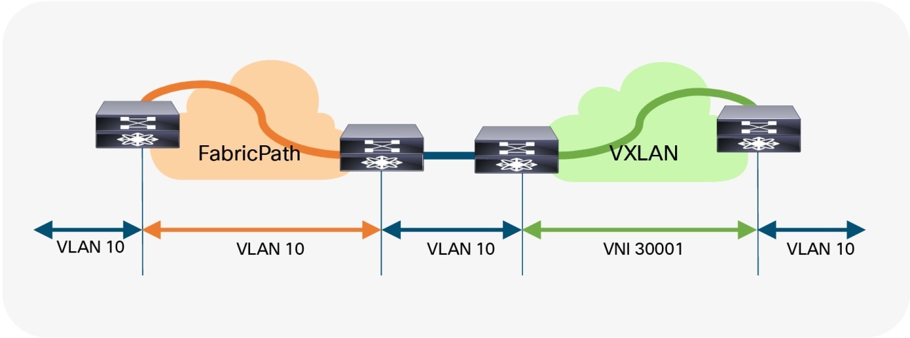
Consistent VLAN Mapping
As shown in the example below, the drawback of using the same VLAN mapping across all nodes is that even though VXLAN can support a significantly larger namespace, the number of Layer 2 identifiers possible across both networks stays at the available VLAN namespace.
VLAN Mapping—Ingress FabricPath Node
vlan 10
mode fabricpath
VLAN Mapping—Egress FabricPath Node
vlan 10
mode fabricpath
VLAN Mapping—Ingress VXLAN Node
vlan 10
vn-segment 30001
VLAN Mapping—Egress VXLAN Node
vlan 10
vn-segment 30001
Scenario 2: Mapping between Different VLANs
The second scenario provides a flexible mapping option for the VLANs. From the first FabricPath node (ingress), the VLAN stays consistent until it reaches the first VTEP (ingress). At this point, the VLAN is mapped to a VNI and transported across the overlay. At the destination VTEP (egress), the VNI is mapped to a different VLAN (Figure 13).
Flexible VLAN Mapping
In addition to the flexible VLAN Mapping, the port-VLAN translation approach in VXLAN can provide additional flexibility. This approach allows translation of the incoming VLAN from the brownfield (FabricPath) so that the VXLAN environment will never learn of the originally used FabricPath VLAN (Figure 14).
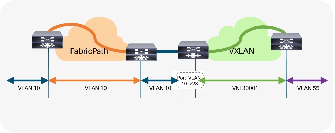
Flexible VLAN Mapping with Port-VLAN Translation
The drawback to this scenario resides in the fact that VLANs change at various stages. While this method allows use VXLAN’s larger namespace, the translations and mapping at various stages can introduce operational complexity.
VLAN Mapping—Ingress FabricPath Node
vlan 10
mode fabricpath
VLAN Mapping—Egress FabricPath Node
vlan 10
mode fabricpath
VLAN Mapping—Ingress VXLAN Node (Without port-VLAN)
vlan 10
vn-segment 30001
VLAN Mapping—Ingress VXLAN Node (With port-VLAN)
vlan 23
vn-segment 30001
interface port-channel 10
switchport vlan mapping enable
switchport vlan mapping 10 23
switchport trunk allowed vlan 23
VLAN Mapping—Egress VXLAN Node
vlan 55
vn-segment 30001
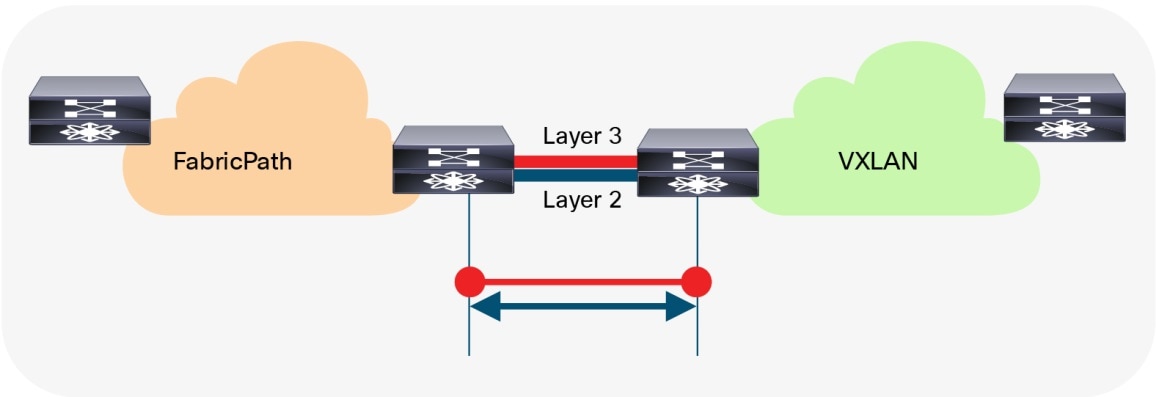
Interconnecting the brownfield network with the greenfield network via Layer 3 is crucial to allow communication between the endpoints in different IP subnets at various stages of the migration (Figures 15–16). The idea is to allow endpoints the ability to communicate with other endpoints in the same subnet or different subnets before, during, and after migration.
Note: Even when seamless workload migration is not required, a Layer 3 interconnect between brownfield and greenfield is still necessary. However, the requirement for a direct interconnection can be relaxed, and external connectivity of the individual environments can be used for a per-subnet migration.
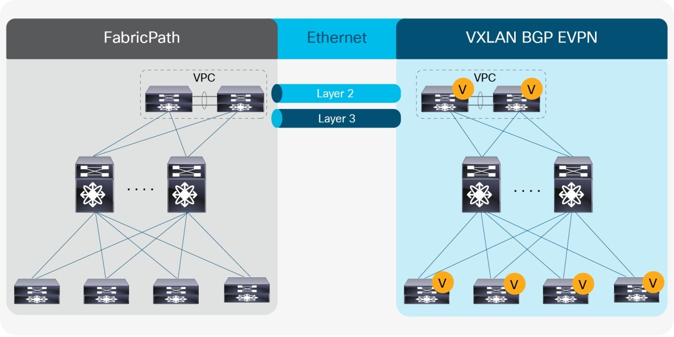
Overview: Brownfield-Greenfield Interconnection (Direct)
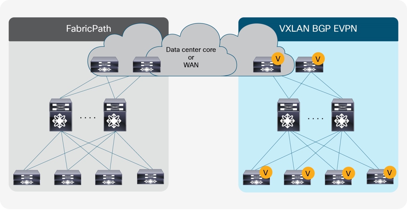
Overview: Brownfield-Greenfield Interconnection (Data Center Core or WAN)
For the Layer 3 interconnection, we establish a route peering session between a pair of nodes in the greenfield (VXLAN) and brownfield (FabricPath) network respectively. As we are focusing on the migration from a Cisco FabricPath network to a VXLAN BGP EVPN network, we interconnect the networks with a Virtual Route Forwarding (VRF)-aware approach, thereby using the multitenancy capability present in the greenfield VXLAN BGP EVPN network.
Note: Workloads or endpoints in the VXLAN BGP EVPN network are always present in a VRF instance other than VRF default or management.
As mentioned earlier, the nodes chosen in the greenfield network can represent a border node or any other switch that provides the VXLAN BGP EVPN tunnel endpoint functionality. In the brownfield network, the nodes for the interconnection should represent the Layer 2–Layer 3 demarcation. In the case of Cisco FabricPath, that demarcation is found at various locations, depending on the topology or first-hop gateway mode (or both) that is chosen. The topologies introduced when describing the Layer 2 interconnection options are equally applicable here:
● Access/aggregation with first-hop gateway at aggregation using VPC and traditional FHRP (HSRP)
● Leaf-and-spine with the first-hop gateway at leaf using VPC and traditional FHRP (HSRP)
● Leaf-and-spine with the first-hop gateway at spine (anycast HSRP)
Note: This guide considers the Layer 2–Layer 3 interconnect to be separate connections, hence separate physical interfaces are being used. In certain scenarios, the same physical connection can be employed for carrying Layer 2 and Layer 3 traffic with the use of the dynamic-routing-over-VPC feature. However, for this scenario, this feature must be supported on both the FabricPath VPC+ as well as in the VXLAN BGP EVPN VPC environment.
Routing Protocol Choice
Many considerations must be taken into account when choosing routing protocols. Many or all may be viable for providing Layer 3 routing exchange between network nodes, but in the case of migration from a fabric network to a VXLAN BGP EVPN network, the following considerations are important in the context of this guide:
● Greenfield network with VXLAN BGP EVPN
● Clean routing domain separation
● Extensive routing policy capability
● VRF awareness
Given that BGP provides these capabilities and meets the requirements, we will focus on the Layer 3 interconnection with external BGP (eBGP) as the routing protocol of choice.
Note: Other routing protocols can equally accommodate the requirement for the Layer 3 interconnect, but they might require additional redistribution configuration.
Note: By using VXLAN BGP EVPN in the greenfield network and eBGP for the Layer 3 interconnect, all host routes (/32 and /128) by default are advertised to the eBGP peers in the brownfield network. For the migration, it might be beneficial to filter out these host routes so as to not overwhelm the available scale in the brownfield environment. Recall that in the brownfield environment, only non-host (/32 and /128) routing prefixes are advertised for reachability.
VRF Mapping
Note: By using VRF-lite for the Layer 3 interconnect between the brownfield and greenfield network, all existing best practices for VXLAN BGP EVPN and VRF-lite are applicable, even though some configurations may have been omitted here for the sake of brevity.
Scenario 1: 1:1 Mapping Between VRFs
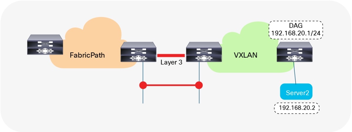
The first scenario follows a consistent mapping where all the VRFs from the FabricPath network are mapped to a matching VRF in the VXLAN BGP EVPN network. To accommodate this mapping, we will employ a VRF-lite approach by using subinterfaces and Layer 3 ECMP at the interconnect. The result is per-VRF eBGP peering at the Layer 2–Layer 3 demarcation node in the brownfield FabricPath network and at the VXLAN BGP EVPN border node in the greenfield network. A point-to-point IP subnet per-VRF is employed, and the routing table between the two environments is exchanged. For the IP subnets in the FabricPath network, we have to ensure that the associated network prefixes are advertised into BGP. In the example in Figure 17, Switched Virtual Interface (SVI) 10 is instantiated on the VXLAN BGP EVPN network with distributed IP anycast gateway 192.168.10.1. The first-hop gateway for IP subnet 192.168.20.0/24 is instantiated on the brownfield FabricPath network with HSRP. Routed traffic between these two subnets traverses the Layer 3 interconnect between the two networks.
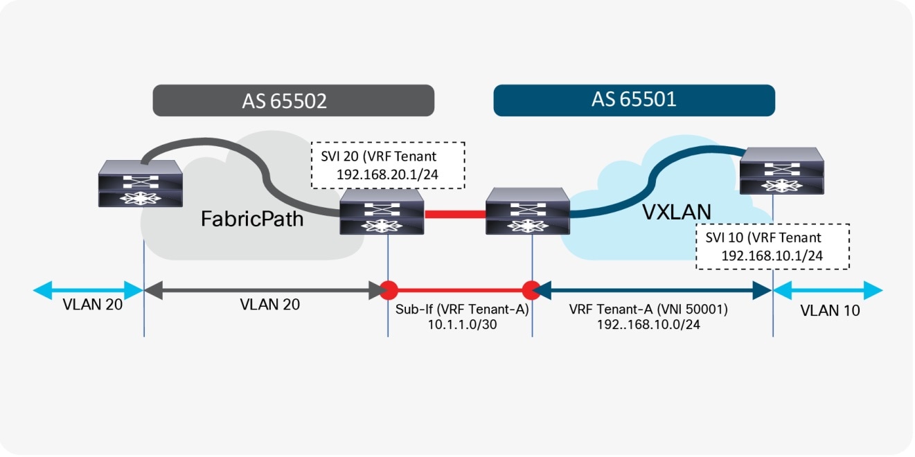
Consistent Per-VRF Mapping
Layer 3 Configuration—FabricPath Border Node (Named-to-Named)
vlan 20
mode fabricpath
!
vrf context Tenant-A
!
interface vlan 20
vrf member Tenant-A
ip address 192.168.20.201/24
hsrp 10
ip 192.168.20.1
!
interface ethernet 1/10
no switchport
!
interface ethernet 1/10.20
encapsulation dot1q 20
vrf member Tenant-A
ip address 10.1.1.2/30
!
router bgp 65502
vrf Tenant-A
address-family ipv4 unicast
network 192.168.20.0/24
neighbor 10.1.1.1
remote-as 65501
update-source Ethernet1/10.20
address-family ipv4 unicast
Layer 3 Configuration—VXLAN BGP EVPN Border Node (Named-to-Named)
vlan 2001
vn-segment 50001
!
interface vlan 2001
vrf member Tenant-A
ip forward
no ip redirects
no shutdown
!
vrf context Tenant-A
vni 50001
rd auto
address-family ipv4 unicast
route-target both auto
route-target both auto evpn
!
interface nve 1
member vni 50001 associate-vrf
!
interface ethernet 1/10
no switchport
!
interface ethernet 1/10.20
encapsulation dot1q 20
vrf member Tenant-A
ip address 10.1.1.1/30
!
router bgp 65501
vrf Tenant-A
address-family ipv4 unicast
advertise l2vpn evpn
neighbor 10.1.1.2
remote-as 65502
update-source Ethernet1/10.20
address-family ipv4 unicast
Scenario 2: Mapping from Default VRF
The second scenario follows a many-to-one mapping where the VRF “default” in the FabricPath network is mapped to a named VRF in the VXLAN BGP EVPN network (Figure 18). To accommodate this mapping, we employ a VRF-lite approach using the physical interface in the brownfield network and the greenfield network. For redundancy and load sharing, Layer 3 ECMP is used at the interconnect. As a result, there is one eBGP peering in the VRF default (global routing table/underlay) at the Layer 2–Layer 3 demarcation node in the brownfield FabricPath network, and a named VRF eBGP peering at the VXLAN BGP EVPN border node in the greenfield network. As before, a point-to-point IP subnet is used for peering, and the routing table between the two environments is exchanged. For each IP subnet in the FabricPath network, we must ensure the associated network prefixes are respectively advertised into BGP.
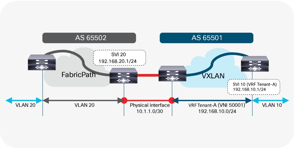
VRF Default to VRF Tenant-A
Layer 3 Configuration—FabricPath Border Node (Default-to-Named)
vlan 20
mode fabricpath
!
interface vlan 20
ip address 192.168.20.201/24
hsrp 10
ip 192.168.20.1
!
interface ethernet 1/10
ip address 10.1.1.2/30
!
router bgp 65502
address-family ipv4 unicast
network 192.168.20.0/24
neighbor 10.1.1.1
remote-as 65501
update-source Ethernet1/10
address-family ipv4 unicast
Layer 3 Configuration—VXLAN BGP EVPN Border Node (Default-to-Named)
vlan 2001
vn-segment 50001
!
interface vlan 2001
vrf member Tenant-A
ip forward
no ip redirects
no shutdown
!
vrf context Tenant-A
vni 50001
rd auto
address-family ipv4 unicast
route-target both auto
route-target both auto evpn
!
interface nve 1
member vni 50001 associate-vrf
!
interface ethernet 1/10
no switchport
vrf member Tenant-A
ip address 10.1.1.1/30
!
router bgp 65501
vrf Tenant-A
address-family ipv4 unicast
advertise l2vpn evpn
neighbor 10.1.1.2
remote-as 65502
update-source Ethernet1/10
address-family ipv4 unicast
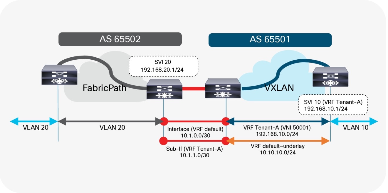
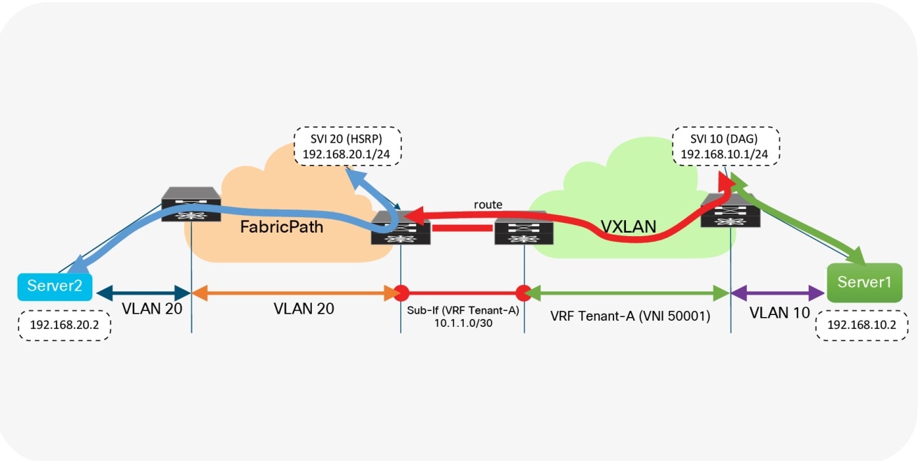
If it is necessary to allow the VXLAN BGP EVPN underlay to be reachable from the FabricPath network, an additional eBGP peering session can be established from the brownfield VRF default to the greenfield VRF default (Figure 19). Since we require a routing session from the VXLAN BGP EVPN network in both the VRF default and VRF Tenant-A into the VRF default on the FabricPath side, we either require two physical interfaces or we must use subinterfaces.
The example below shows how this can be achieved using subinterfaces. Note that while, as before, SVI 20 (HSRP) and SVI 20 (DAG) have been instantiated on the brownfield and greenfield networks, respectively, in this example, 10.10.10.0/24 is the underlay subnet on the greenfield VXLAN network that must be advertised over to the brownfield FabricPath network.
VRF default to VRF default and Tenant-A
Layer 3 Configuration—FabricPath Border Node (Default-to-Default/Named)
vlan 20
mode fabricpath
!
interface vlan 20
ip address 192.168.20.201/24
hsrp 10
ip 192.168.20.1
!
interface ethernet 1/10
no switchport
ip address 10.1.0.2/30
!
interface ethernet 1/10.20
encapsulation dot1q 20
ip address 10.1.1.2/30
!
router bgp 65502
address-family ipv4 unicast
network 192.168.20.0/24
neighbor 10.1.0.1
remote-as 65501
update-source Ethernet1/10
address-family ipv4 unicast
neighbor 10.1.1.1
remote-as 65501
update-source Ethernet1/10.20
address-family ipv4 unicast
Layer 3 Configuration—VXLAN BGP EVPN Border Node (Default-to-Default/Named)
vlan 2001
vn-segment 50001
!
interface vlan 2001
vrf member Tenant-A
ip forward
no ip redirects
no shutdown
!
vrf context Tenant-A
vni 50001
rd auto
address-family ipv4 unicast
route-target both auto
route-target both auto evpn
!
interface nve 1
member vni 50001 associate-vrf
!
interface ethernet 1/10
no switchport
ip address 10.1.0.1/30
!
interface ethernet 1/10.20
encapsulation dot1q 20
vrf member Tenant-A
ip address 10.1.1.1/30
!
router bgp 65501
address-family ipv4 unicast
network 10.10.10.0/24
neighbor 10.1.0.2
remote-as 65502
update-source Ethernet1/10
address-family ipv4 unicast
vrf Tenant-A
address-family ipv4 unicast
advertise l2vpn evpn
neighbor 10.1.1.2
remote-as 65502
update-source Ethernet1/10.20
address-family ipv4 unicast
Default Gateway Migration Considerations
While interconnecting the brownfield network with the greenfield network is an important task, the placement of the first-hop gateway is equally important. During migration from a Cisco FabricPath network to a VXLAN BGP EVPN network, the first-hop gateway cannot simultaneously be active in both the brownfield and greenfield network, because the two first-hop gateways operate in different modes. While the brownfield operates in a traditional FHRP or anycast HSRP mode, the VXLAN BGP EVPN greenfield uses the distributed IP anycast gateway (DAG). These two different first-hop gateway modes are not compatible and so cannot be active at the same time.
Note: To disable the Fabricpath First Hop Gateway as part of the migration, delete the SVI configuration completely. Do not shut down the Fabricpath Gateway SVI as this can lead to loops.
Scenario 1: Centralized First-Hop Gateway
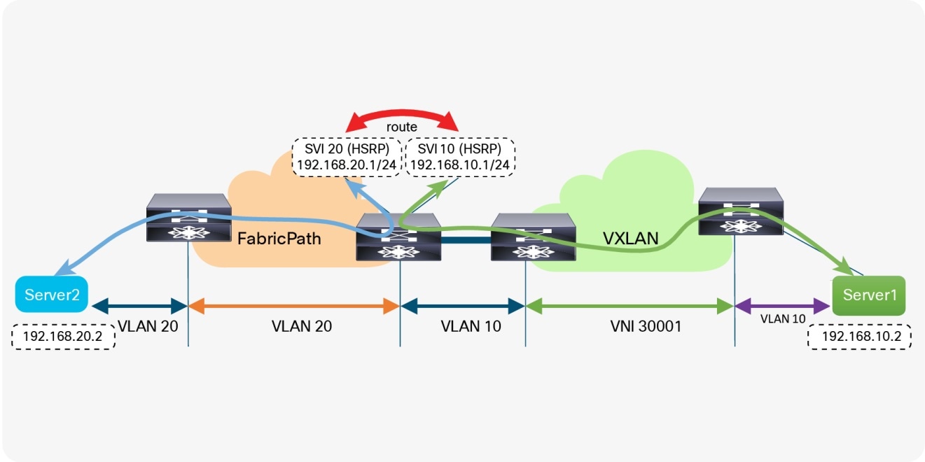
Since the migration starts from the brownfield network, the first-hop gateway used to establish communication between IP subnets is initially maintained there. This placement implies that the VXLAN BGP EVPN fabric initially provides only Layer 2 services, and the endpoints already migrated to the VXLAN BGP EVPN fabric send traffic to the brownfield network across the Layer 2 interconnect. Intersubnet or routed traffic from and to endpoints in the greenfield network, trombones over the Layer 2 interconnect to reach the first-hop gateway on the brownfield side, as shown in Figure 20.
First-Hop Gateway in Brownfield Network
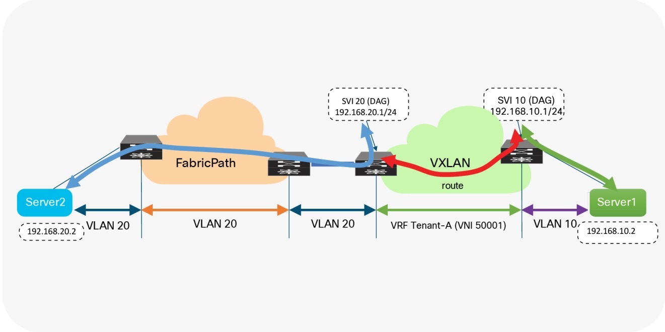
Once all the workloads belonging to a given IP subnet (VLAN) are migrated into the VXLAN BGP EVPN fabric, it is possible to also migrate the first-hop gateway into the VXLAN BGP EVPN domain. This migration is done by turning on DAG routing in the VLAN or VNI associated with the corresponding IP subnet and deconfiguring the first-hop gateway function on the brownfield network devices (Figure 21). In this way, the border nodes never need to have the distributed IP anycast gateway, assuming they have no directly attached workloads.
First-Hop Gateway in Brownfield and Greenfield Networks
First-hop configuration—FabricPath Node
vlan 20
mode fabricpath
!
vrf context Tenant-A
!
interface vlan 20
vrf member Tenant-A
ip address 192.168.20.201/24
hsrp 10
ip 192.168.20.1
!
First-Hop Configuration—VXLAN BGP EVPN Leaf Node
fabric forwarding anycast-gateway-mac 2020.0000.00aa
!
vlan 10
vn-segment 30001
!
vrf context Tenant-A
vni 50001
rd auto
address-family ipv4 unicast
route-target both auto
route-target both auto evpn
!
interface vlan 10
vrf member Tenant-A
ip address 192.168.10.1/24
fabric forwarding mode anycast-gateway
Scenario 2: Anycast First-Hop Gateway
In the second scenario, the first-hop gateway is immediately migrated from the brownfield network to the greenfield network before the workload migration begins (Figure 22). In this approach, no change to the migration infrastructure is required once migration begins. In contrast to the first scenario, where we have a centralized first-hop gateway and later move the function to a DAG once all endpoints in that associated subnet are migrated, in this scenario, we move to the DAG first and maintain that state during the lifecycle of the network. Note that in this scenario, the DAG is also instantiated at the border nodes. This serves as the first-hop gateway for the workloads in the brownfield environment. As workloads move over to the VXLAN BGP EVPN network, their directly attached leaf takes over the first-hop gateway functionality.
First-Hop Gateway Greenfield Network Only
First-Hop Configuration—VXLAN BGP EVPN Nodes
fabric forwarding anycast-gateway-mac 2020.0000.00aa
!
vlan 10
vn-segment 30001
!
vlan 20
vn-segment 30002
!
vrf context Tenant-A
vni 50001
rd auto
address-family ipv4 unicast
route-target both auto
route-target both auto evpn
!
interface vlan 10
vrf member Tenant-A
ip address 192.168.10.1/24
fabric forwarding mode anycast-gateway
!
interface vlan 20
vrf member Tenant-A
ip address 192.168.20.1/24
fabric forwarding mode anycast-gateway
Although neither first-hop gateway migration approach is preferred, each approach has its advantages and disadvantages. The second scenario has in its favor the fact that the DAG is used early, thereby providing experience in using it before migrating the major workloads. On the other hand, scenario 2 also has the disadvantage that, until the workload migration begins, traffic will always trombone over the Layer 2 interconnect.
Regardless of the chosen scenario, the preparatory steps required before the migration begins are similar.
Cisco Dynamic Fabric Automation
For Cisco FabricPath environments that are enhanced with Cisco Dynamic Fabric Automation software, an intermediate step is required for the brownfield network. Before migrating from Dynamic Fabric Automation to VXLAN BGP EVPN, the DAG in Dynamic Fabric Automation must first be moved to a centralized first-hop gateway approach. This move can be achieved by making the Dynamic Fabric Automation fabric a Layer 2–only fabric by disabling the DAG. The VXLAN BGP EVPN fabric must provide the first-hop gateway functionality on the border nodes for all the endpoints that are part of the Dynamic Fabric Automation fabric (Layer 2 interconnect). This approach is similar to that presented in the previous section, with a slight variation.
Premigration Preparation—First-Hop Gateway
For the first-hop gateway migration we want to make sure that the change is as seamless as possible for the endpoints. The endpoints are typically configured with a default gateway IP to reach any destination outside their local IP subnet. The default gateway IP-to-MAC binding at the endpoint is resolved via the Address Resolution Protocol (ARP). Although it is easy to align the IP addresses from FHRP to the DAG, the alignment of the virtual MAC address to the anycast gateway MAC requires additional considerations.
With HSRP, the virtual MAC address for the first-hop gateway is derived from the HSRP version (1 or 2) and the configured HSRP group. It is commonly seen that HSRP groups change on a per-VLAN or per-SVI basis. The DAG used in VXLAN BGP EVPN follows a different approach from the per-group virtual MAC employed by HSRP. For the DAG, a global anycast gateway MAC is defined. This means that the virtual MAC—or more accurately the anycast gateway MAC—is the same for all first-hop gateways on the given node. In fact, the same anycast gateway MAC is shared by all the nodes in a given fabric.
Clearly, with these different approaches for virtual MAC assignments, some mechanism is needed to align the virtual MACs to allow a migration from the HSRP MAC to the anycast gateway MAC.
Since the endpoints are part of the brownfield network, they will store the default gateway IP–to–HSRP virtual MAC binding in their ARP cache. Eventually, when the DAG is enabled, the ARP cache of the endpoints should be updated to have the gateway IP mapped to the anycast gateway MAC. Clearly, manually updating the ARP cache of every single endpoint is tedious and impractical. Hence, in the brownfield network, even before starting the migration, the HSRP virtual MAC address for each VLAN or subnet should be updated to be the same as the anycast gateway MAC, via a configuration update, as shown here:
HSRP virtual MAC configuration—FabricPath nodes
interface vlan 20
vrf member Tenant-A
ip address 192.168.20.201/24
hsrp 10
ip 192.168.20.1
mac-address 2020.0000.00aa
Anycast gateway MAC configuration—VXLAN BGP EVPN nodes
fabric forwarding anycast-gateway-mac 2020.0000.00aa
After the change from the HSRP group-based virtual MAC address on the brownfield network side (FabricPath) to the anycast gateway MAC, we also must ensure that all endpoints learn about that change. Changing the state of FHRP from active to standby enables the first-hop gateway instance to send out a gratuitous ARP (GARP) message to inform all endpoints about the updated IP-to-MAC binding. As a result of this state change and GARP, the endpoints either update their ARP cache or invalidate their ARP cache and trigger an ARP request for the first-hop gateway’s MAC address. As a result, the new virtual MAC address (anycast gateway MAC) for the first-hop gateway is learned at the endpoints.
Note: The practice of changing the FHRP virtual MAC followed by a state change (active-standby) results in the highest probability that connected endpoints will relearn the first-hop gateway’s new virtual MAC address. Nonetheless, a possibility remains that some endpoints will not honor the signalization through GARP or have a static MAC entry for the first-hop gateway. These endpoints require manual intervention to flush their ARP cache and hence, we recommend performing this action during a Maintenance Window.
Once the premigration steps for the first-hop gateway are completed, the migration of workloads can be seamlessly performed. At the time when the old first-hop gateway (HSRP) must be disabled and the new first-hop gateway (DAG) enabled, a small traffic disruption may be observed. Hence, we recommend performing such first-hop gateway changes during a maintenance window. We reiterate that, for a given IP subnet or VLAN, FHRP in the brownfield network and the DAG in the greenfield network should never be enabled at the same time. Otherwise, unexpected forwarding behavior, ARP table mis-programming, and traffic forwarding failure can result.
The preceding sections gave a detailed account of different aspects of migrating a brownfield Cisco FabricPath network to a greenfield VXLAN BGP EVPN network. Although the individual steps have been explained, we have not yet described the migration process in chronological order. This section summarizes the main steps of the migration.
Locating the Interconnection Nodes in the Brownfield and Greenfield Network
It is important to define the location of where the Layer 2 to Layer 3 demarcation exists in the brownfield network (Figure 23). In the greenfield network, the interconnection point can be at any border node or similar node that can serve the routing and bridging requirements.
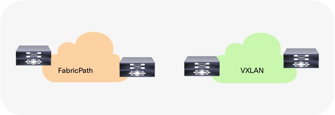
Interconnection Location
Building a Layer 3 interconnect
The Layer 3 interconnect or Layer 3 external connectivity has to exist in the brownfield and greenfield network (Figure 24). Ensure that the IP subnet and associated prefix local to each of the respective environments are advertised and learned in the adjacent network.
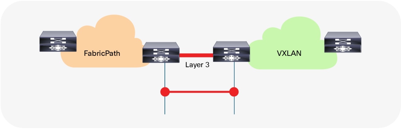
Layer 3 interconnect
Building a Layer 2 Interconnect
The Layer 2 Interconnect is necessary if only seamless workload mobility and first-hop gateway sharing are required (Figure 25). If the brownfield and greenfield network needs to share the same IP subnet, the Layer 2 interconnect is necessary (Figure 25).
Layer 2 Interconnect
Defining the First-Hop Gateway Approach
The choice of first-hop gateway approach should be made depending on whether the brownfield network provides the first-hop gateway during the migration (Scenario 1) or the greenfield network will take over this function as soon as possible (Scenario 2). Two different first-hop gateway modes (HSRP and DAG) cannot be simultaneously enabled for the same IP subnet. Only one first-hop gateway mode at a time must be enabled, with the goal being to migrate to the DAG at the end of the migration. See Figure 26.
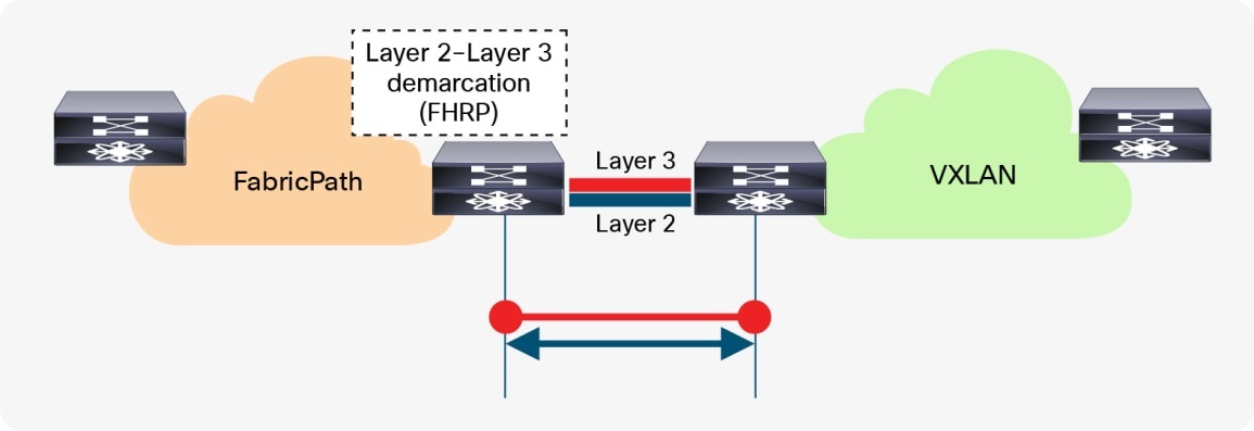
Layer 2–Layer 3 Demarcation (FHRP) as First-Hop Gateway
Aligning the First-Hop Gateway Information (Virtual MAC and Virtual IP)
To facilitate seamless migration of the first-hop gateway, the virtual MAC and first-hop gateway IP address must be aligned first. To ensure that all endpoints learn the new virtual MAC (specifically the anycast gateway MAC) for the first-hop gateway, a state change has to be performed on the FHRP-based first-hop gateway in the brownfield network.
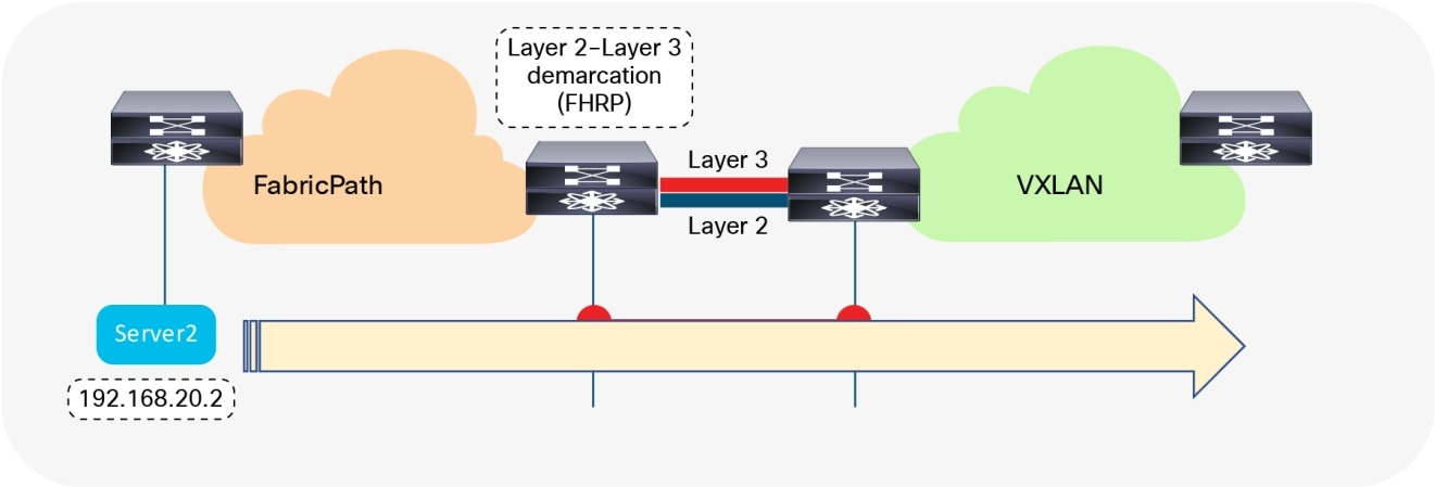
Performing the workload migration
Once the interconnection at Layer 2 and Layer 3 is ready and the first-hop gateway has been respectively aligned, workloads can be migrated between the brownfield and the greenfield network (Figure 27). This can be performed by using virtual machine mobility (cold or hot move) or by physically recabling workloads to the greenfield network.
Workload Migration
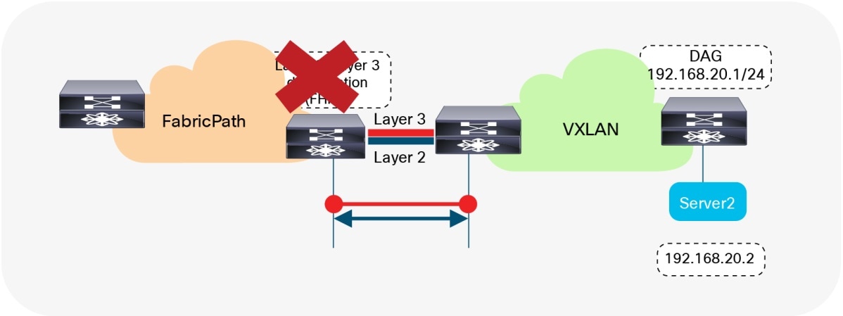
Migrate and Decommission Unnecessary First-Hop Gateway
Once the workloads have been migrated, the brownfield first-hop gateway can be decommissioned (Figure 28) and the greenfield first-hop gateway activated (Scenario 1). The decommission is not necessary with Scenario 2, where the DAG is enabled on the greenfield network before the workload migration begins.
Decommission First-Hop Gateway
Decommission the Layer 2 Interconnect
Although the Layer 3 external connectivity or interconnect might remain necessary for the lifecycle of the remaining resources in the brownfield network, the Layer 2 interconnect for the first-hop gateway can be decommissioned once the workload migration is complete. It is a good practice not to have any Layer 2 interconnects if they are not required, to avoid the possibility of Layer 2 loops (Figure 29).
Decommission Layer 2 Interconnect
Cisco Data Center Network Manager
Using DCNM for Migration
Among the many capabilities of Cisco Data Center Network Manager (DCNM), and perhaps its most appealing, is its ability to manage multiple network deployments across the Cisco family of switches. The same DCNM instance can manage legacy access-aggregation deployments, FabricPath deployments, and VXLAN BGP EVPN deployments. With the Fabric Builder introduced in DCNM version 11, there is an “easy fabric” option to manage both brownfield and greenfield VXLAN EVPN deployments (see Figure 30). Day 0/1/2 operations associated with a fabric are all integrated together into the fabric builder with a closed-loop configuration compliance feature for tracking configuration drifts from the user specified intent. Overlay networks/vrfs can be provisioned on the switches via a top-down push mechanism along with other configuration options for network provisioning for supporting L4-7 services and external connectivity from the border devices with VRF Lite and other hand-offs (e.g. VXLAN to SR/MPLS). In addition, the same DCNM instance can be employed to interconnect multiple fabrics for Layer-2/Layer-3 DCI using VXLAN EVPN Multi-Site technology using a Multi-Site Domain fabric construct and an associated workflow for setting up the DCI underlay and overlay peering between different member fabrics. For more information about the DCNM 11 capabilities, refer to Cisco DCNM LAN Fabric Configuration Guide.
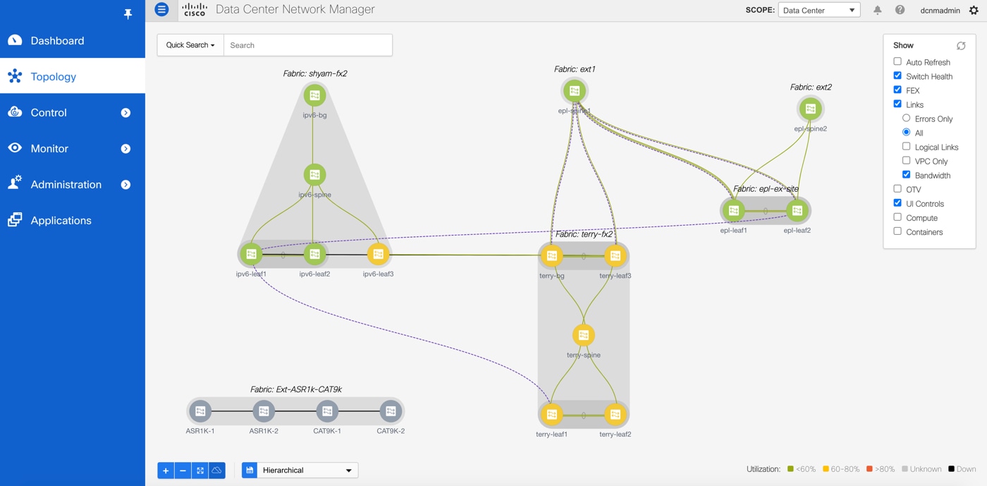
Cisco Data Center Network Manager Managing Brownfield and Greenfield Deployments
DCNM can simultaneously manage VXLAN EVPN fabrics using the Easy Fabric option and other deployments such as classic 3-tier access-agg-core, FabricPath, etc. using External/Classic LAN fabrics. The External fabrics may have a mix of NX-OS and non-NXOS devices (e.g. Cisco IOS-XE, IOS-XR, or 3rd party). When migrating a brownfield Cisco FabricPath network to a greenfield VXLAN BGP EVPN network, the Cisco DCNM can help in the following ways:
● Set up the greenfield VXLAN BGP EVPN network using the Easy Fabric Template (using the Easy_Fabric_11_1 fabric template)
● Import the existing FabricPath network into the External or Classic LAN fabric (using the External_11_1 or Classic_LAN fabric template)
● Set up the Layer 3 Interconnect from the greenfield VXLAN BGP EVPN network to the brownfield FabricPath network
● Set up the VPC+ connection between the brownfield FabricPath network and the greenfield VXLAN BGP EVPN network (Layer 2 interconnect)
● Help in migrating the first-hop gateway from the brownfield network to the greenfield network
Performing Migration using DCNM
The VXLAN EVPN fabric can be easily provisioned using the DCNM fabric builder by bringing up the switches using the 2-phase POAP or bootstrap function. A new fabric must be created in the DCNM, using the Easy_Fabric_11_1 template, and the bootstrap option must be enabled as indicated in Figure 31.
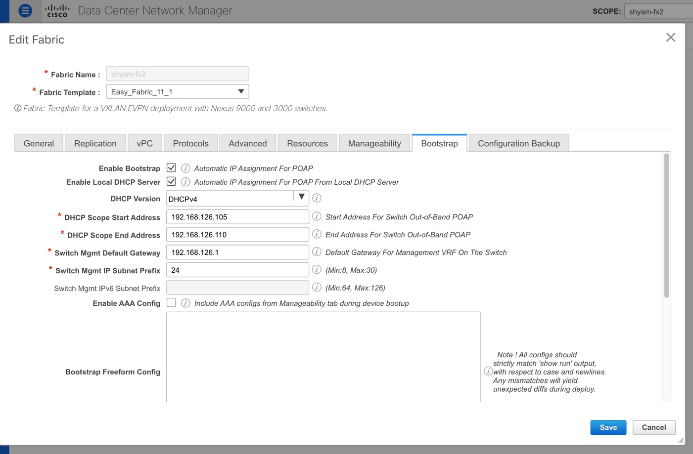
Cisco DCNM Fabric Template Bootstrap Settings for Greenfield Deployments
Subsequently, once switches have been wired and they are powered on, they will go through the Power-On-Auto-Provisioning (POAP) process and be discovered by the DCNM. The switches can be imported into the DCNM with minimal inputs such as the management IP address, host name, and admin password. Post import, the DCNM will discover the connectivity between the various switches and display it in the Fabric Builder topology view. Users just need to set the appropriate switch role, typically spine, border etc., setup the one-click vPC pairing as applicable, and then click the Save-n-deploy button. The entire configuration of all the switches will be generated by the DCNM based on the best practice recommendations from Cisco. In this way, the greenfield VXLAN EVPN fabric can be rapidly provisioned with the DCNM.
Next, a new External or Classic LAN fabric can be created by the user. The switches in the existing FabricPath network can be imported into this fabric by just providing an appropriate seed IP and an appropriate hop count. DCNM will discover all the switches within the specified diameter, and the selected switches can be imported into the fabric in a non-disruptive manner. In other words, a brownfield switch import is performed without making any changes to the existing configuration on the switches.
Now that both the fabrics are prepared, for Layer-2 interconnect between the two fabrics, users can use the interface deployment option for configuring back-to-back vPCs between the aggregation devices on the FabricPath network and the appropriate border devices on the VXLAN EVPN network. Similarly, for Layer-3 interconnect, users can employ some of the built-in templates in DCNM for setting up the route peering between the two fabrics. Alternatively, users can also create their own custom templates for either of these interconnectivity options and use it to push custom configurations of choice to the respective switches. Note that for Layer-3 interconnect, typically on the border devices on the VXLAN EVPN network, appropriate VRF(s) must be provisioned. Layer-3 interconnect comes into play once the first gateway is moved over from the FabricPath side to the VXLAN EVPN side where it is realized as a distributed IP Anycast Gateway. Provisioning of overlay networks and VRFs from the DCNM is described next.
At least one VRF is required on the VXLAN EVPN fabric. The VRF can be defined using the Control->VRFs workflow as depicted in Figure 32.
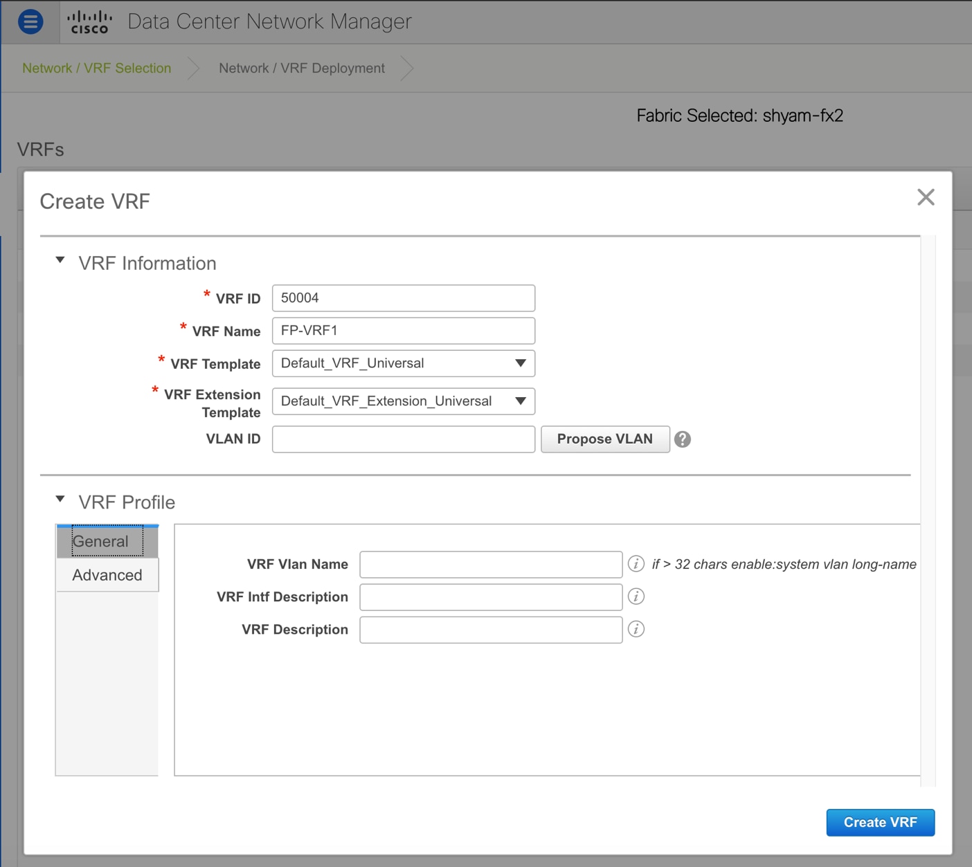
Creating a New VRF with the Cisco DCNM Overlay Management Workflow
The VRF can be provisioned on the border devices as part of the preparation step for migration. In the VXLAN EVPN fabric, overlay networks must be defined on the DCNM, for each VLAN that needs to be migrated from the FabricPath network to the VXLAN EVPN network. For this purpose, the Control->Networks workflow can be employed as depicted in Figure 33. The Layer-2 VNI is auto allocated from a previously configured user-defined pool. The VLAN for the network must be set to be the same one that is used on the existing FabricPath deployment. During the network creation, the Layer-2 Only knob should be checked. This ensures that no VRF is needed for that network.
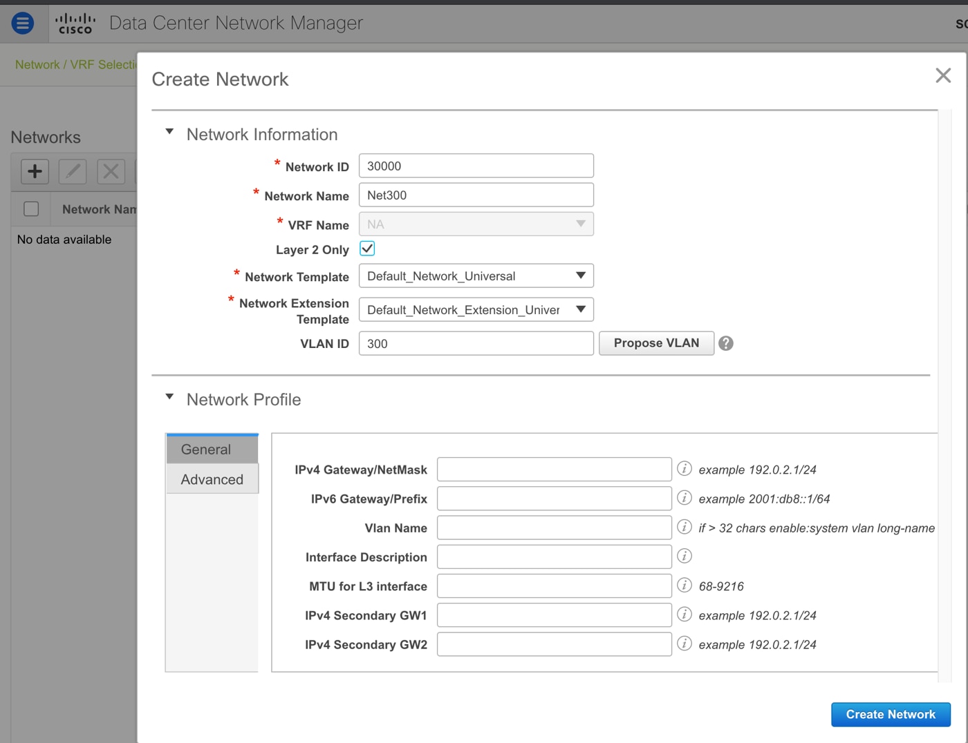
Creating a New Layer-2 VXLAN Overlay Network with Layer-2 Only Flag Enabled
Once this network is deployed on the appropriate leafs and borders on the VXLAN EVPN fabric, the network on the FabricPath side can be seamlessly extended over to the VXLAN EVPN side. As shown in Figure 34, only Layer-2 VXLAN EVPN configuration is pushed to the selected devices. Specifically, workloads in that VLAN can now be moved over from the FabricPath network to the leafs in the VXLAN EVPN fabric. All intra-vlan or intra-network communication between the workloads in the VXLAN EVPN fabric is locally forwarded within the fabric using the advertised EVPN reachability information. All inter-vlan or inter-network communication goes via the border devices and still utilizes the centralized gateway configured on the FabricPath aggregation device.
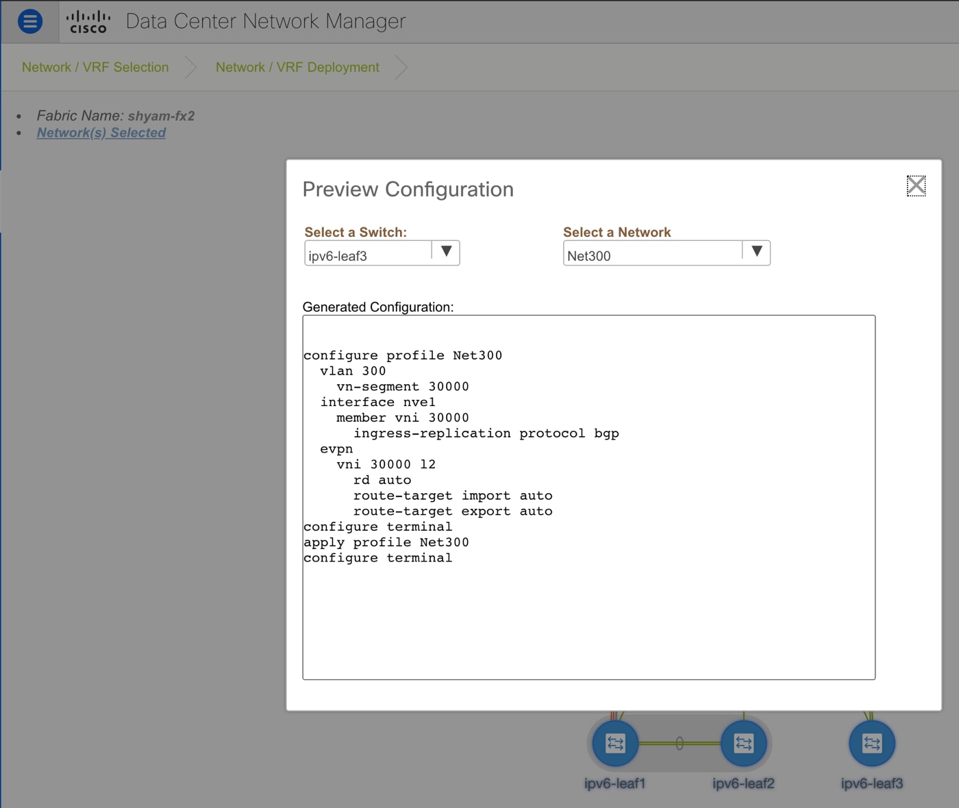
Configuration Preview of the Set of Commands that will be Deployed to the Leafs for the Selected Overlay Network
When users want to migrate the Layer-3 gateway for a given VLAN from the FabricPath side to the VXLAN EVPN side, they can prepare the VXLAN EVPN fabric by selecting that network, editing it, unchecking the Layer-2 Only flag and then specifying the appropriate VRF and gateway IP information for that network (see Figure 35).
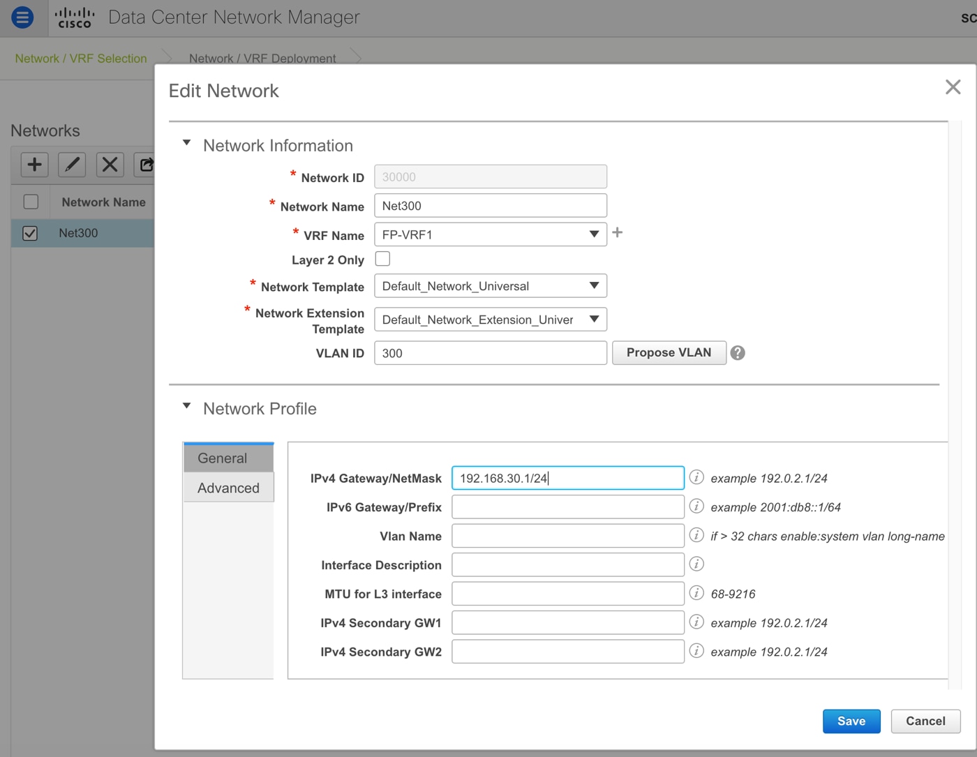
Converting an Overlay Network from Layer-2 to Layer-3 by Specifying the Gateway and Associated VRF
Once these changes are saved, the DCNM automatically moves the network into PENDING state indicated by the Blue color on the devices. Essentially, the DCNM has a state of where the network was already deployed with Layer-2 related EVPN configuration and now generates an update for that configuration by adding the Layer-3 information typically constituting the SVI or IRB interface and the associated VRF (see Figure 36).
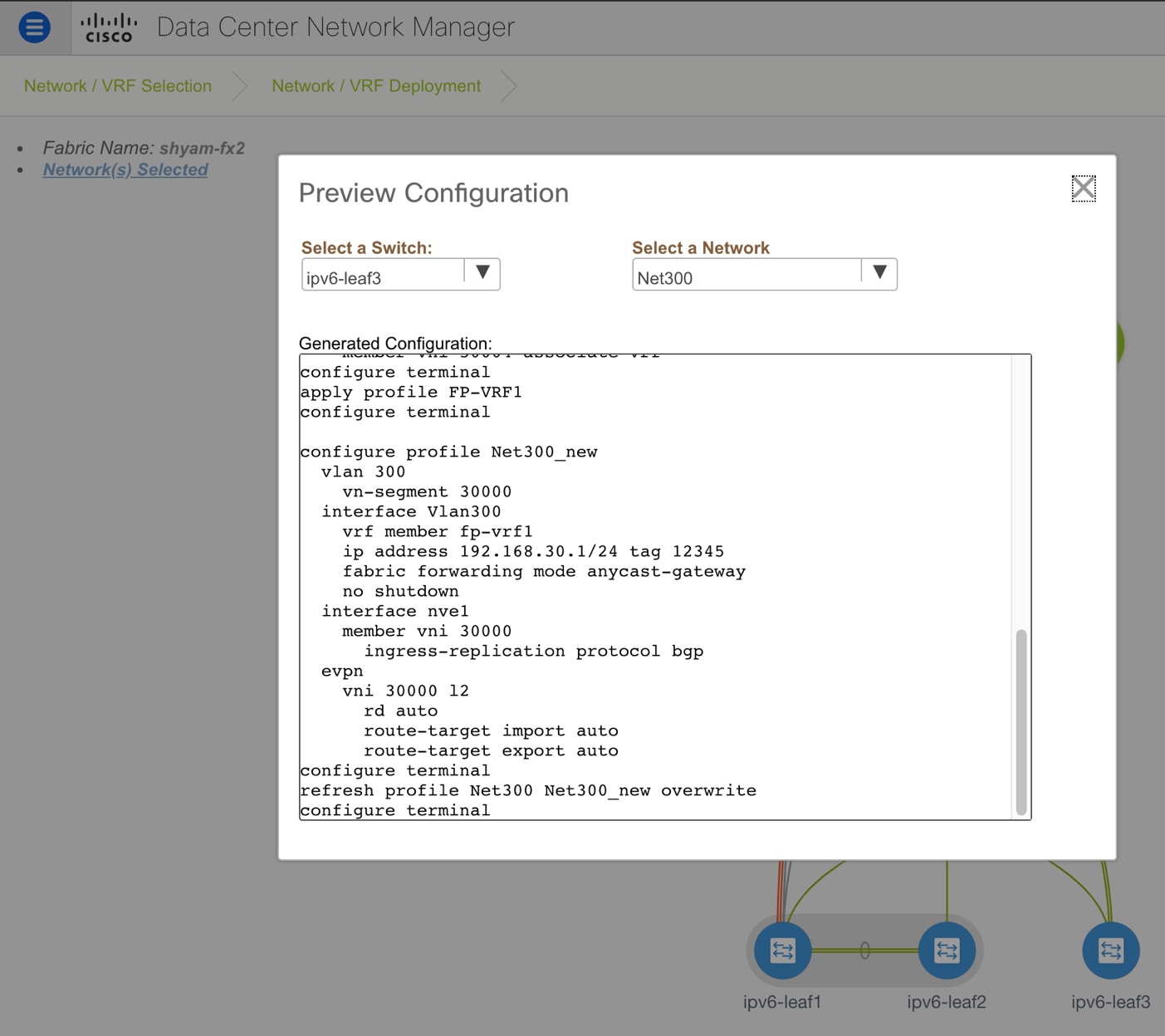
Configuration Preview of the Updated Commands that will be Deployed to the Leafs when the Network is Converted from Layer-2 to Layer-3
If the SVI/IRB interface for that network also needs to be enabled on the border devices, then in the Advanced tab, the “Enable Layer-3 on Border” option must also be selected (see Figure 37).
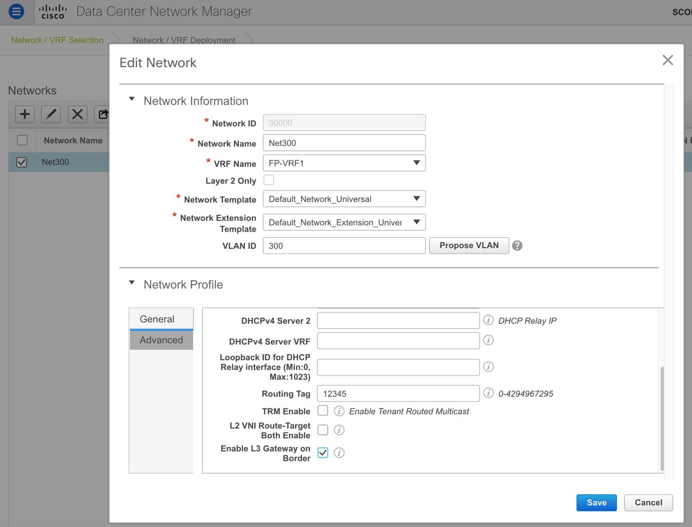
Edit the Overlay Network to Enable the Layer-3 Gateway on the Border Devices
Now the user can shutdown the SVI or Layer-3 gateway on the Fabricpath side and then deploy the pending Layer-3 configuration changes for that network to the respective switches on the VXLAN EVPN fabric with a single click.
For troubleshooting purposes, if the Layer-3 gateway for that network needs to be temporarily moved back to the FabricPath side, the users can perform a few optional actions:
Option 1] From the Control->Interfaces option, the user can select the SVI/IRB interface associated with that network on all switches in that fabric and shut it down by clicking the down arrow button.
Option 2] Alternatively, the user can select the network, edit it, and empty the gateway IP field. Again, the network will go into the pending state and the SVI/IRB interface will be updated with no IP address. This can then be deployed to all the switches at one go.
Subsequently, the user can un-shut the SVI on the FabricPath side to revert back to the old configuration. When the user is ready to migrate the network again, the steps listed above can be undone. In other words, for option 1, the SVIs can be selected and the UP arrow can be clicked to bring them up. For option 2, the user can edit the network and update it with the gateway IP. Again, as before, the network will go into a PENDING state and deploy will pushing the SVI with the updated anycast gateway IP address to all the relevant switches.
Learn more about VXLAN BGP EVPN
Learn more about Cisco FabricPath