Cisco Aironet Access Point Software Configuration Guide for VxWorks
Special Configurations

Table Of Contents

Special Configurations

Setting Up a Repeater Access Point

Using Hot Standby Mode


Special Configurations


This chapter describes how to set up the access point in network roles other than as a root unit on a wired LAN. You can set up an access point as a repeater to extend the range of a wireless network, and you can use Hot Standby mode to use an access point as a backup unit in areas where you need extra reliability. Both configurations require two access points that support and rely upon each other.

This chapter contains the following sections:

Setting Up a Repeater Access Point

Using Hot Standby Mode

Setting Up a Repeater Access Point

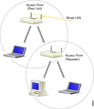
A repeater access point is not connected to the wired LAN; it is placed within radio range of an access point connected to the wired LAN to extend the range of your infrastructure or to overcome an obstacle that blocks radio communication.

The repeater forwards traffic between wireless users and the wired LAN by sending packets to either another repeater or to an access point connected to the wired LAN. The data is sent through the route that provides the greatest performance for the client. When you configure an access point as a repeater, the access point's Ethernet port does not forward traffic. Figure 12-1 shows an access point acting as a repeater.


Note Non-Cisco client devices might have difficulty communicating with repeater access points.


Figure 12-1 Access Point as Repeater

You can set up a chain of several repeater access points, but throughput for client devices at the end of the repeater chain will be quite low. Because each repeater must receive and then re-transmit each packet on the same channel, throughput is cut in half for each repeater you add to the chain.

Omni-directional antennas, like the ones that ship with your access point, are best suited for repeater access points.

If you use EAP authentication on your wireless network, you can set up the repeater access point to authenticate using LEAP. See the "Setting Up a Repeater Access Point as a LEAP Client" section for instructions on enabling LEAP on a repeater.

Follow these steps to set up a repeater access point:


Step 1 Use the Quick Start Guide: Cisco Aironet Access Points and the information in this manual to set up an access point as a root unit on the wired LAN.

Step 2 Write down the root-unit access point's MAC address. The MAC address appears on the label on the bottom of the access point.

Step 3 The repeater access point will need to duplicate some of the root access point's settings. If the root access point has been completely configured, browse to the root access point and write down the following settings so you can refer to them when you set up the repeater access point:

SSID (found on the Express Setup page)

Default IP Subnet Mask (also on the Express Setup page)


Note You can also rely on the DHCP server to assign a default IP subnet mask.


Default Gateway (also on the Express Setup page)


Note You can also rely on the DHCP server to assign a default gateway.


Data rates (found on the AP Radio Hardware page)

WEP settings (found on the AP Radio Data Encryption page)

Authentication Types (found on the AP Radio Data Encryption page)

If the root access point settings have not been changed from the factory defaults, you don't need to write them down. If you reconfigure the root access point, however, you must enter the same settings on the repeater access point.

Step 4 Place the repeater access point within radio range of the root access point.

Step 5 For a 340 series access point, plug one end of the power cord into the access point's power connector. Plug the other end into an electrical outlet.

Step 6 For a 350 series access point, plug an Ethernet cable into the access point's Ethernet port. Plug the other end of the Ethernet cable into the side of the power injector labelled To AP.


Note The repeater access point will not be connected to the wired LAN, so do not run Ethernet cable from the power injector to a switch.


Step 7 Plug the power injector's power cable into an electrical outlet.


Note Step 8, Step 9, and Step 10 describe opening the access point management system using a terminal emulator, but you can use a crossover cable instead. Use a crossover cable to connect the access point's Ethernet port to the Ethernet connection on a computer and browse to the access point's IP address. If you use a crossover cable to open the management system, skip to Step 11.


Step 8 Attach a nine-pin, male-to-female, straight-through serial cable to the access point's serial port. Plug the other end of the serial cable into the COM 1 or COM 2 port on a computer.

Step 9 Use a terminal emulator to open the access point's management system. Assign these port settings to the terminal emulator: 9600 baud, 8 data bits, No parity, 1 stop bit, and Xon/Xoff flow control.

Step 10 When the terminal emulator connects with the access point, press = to display the access point's Summary Status page. If the repeater access point has never been configured before, the Express Setup page will appear instead of the Summary Status page.

Step 11 On the Express Setup page, enter the same SSID that is set on the root access point.


Note Step 12 and Step 13 describe assigning a static IP address, subnet mask, and gateway to the repeater. However, you can rely on your DHCP server to assign these settings if you do not need them to remain fixed. If the repeater will use the DHCP server, skip to Step 14.


Step 12 On the Express Setup page, enter a fixed IP address for the repeater access point in the Default IP address field.

Step 13 Also on the Express Setup page, enter the same settings in the Default IP Subnet Mask and Default Gateway fields that are on the root access point.

Step 14 On the Boot Server Setup page, select none for the Configuration Server Protocol. This setting will maintain a fixed IP address for the repeater access point.

If the root access point configuration has not been changed from the factory defaults, skip to Step 18.

Step 15 On the AP Radio Hardware page, enter the same settings for Data Rates that are on the root access point.

Step 16 On the AP Radio Data Encryption page, enter the same WEP key settings that are on the root access point.

Step 17 Also on the AP Radio Data Encryption page, select the same Authentication Types that are on the root access point.

Step 18 On the AP Radio Advanced page, enter the root access point's MAC address in the Specified access point 1 entry field.

Step 19 On the Express Setup page, select Repeater Access Point as the Role in Radio Network. The access point reboots when you apply this setting.

Step 20 The status LED on the root access point should be steady green, indicating that at least one client device is associated with it. The status LED on the repeater access point is steady green when it is associated with the root access point and has client devices associated with it. The repeater's status LED is steady for 7/8 of a second and off for 1/8 of a second when it is associated with the root access point but has no client devices associated with it. The repeater access point should also appear as associated with the root access point in the root access point's Association Table.


Using Hot Standby Mode

Hot Standby mode designates an access point as a backup for a root access point. The standby access point is placed near the access point it monitors, and it is configured exactly the same as the monitored access point. The standby access point associates to the monitored access point as a client and queries the monitored access point regularly through both the Ethernet and the radio. If the monitored access point fails to respond, the standby access point takes the monitored access point's place in the network.

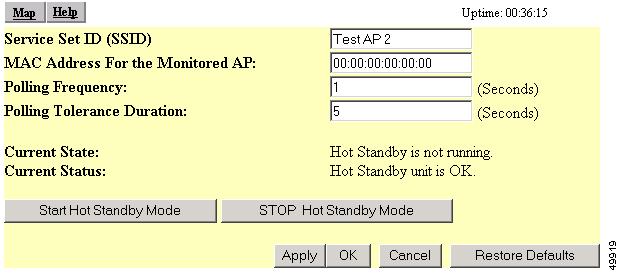
The standby access point's settings should be identical to the settings on the monitored access point. The standby access point must also be able to associate to the root access point as a client. You use the Hot Standby page to set up the standby access point. Figure 12-2 shows the Hot Standby page.

Figure 12-2 Hot Standby Page


Note The Current State field varies depending on the hot standby status. It can display Hot Standby is not running, Hot Standby is initializing, or Hot Standby is monitoring and protecting. The change appears after you refresh the screen.


Follow this link path to reach the Hot Standby page:

On the Summary Status page, click Setup.

On the Setup page, click Cisco Services under Services.

On the Cisco Services Setup page, click Hot Standby Management.


Note Wireless client devices associated to the standby access point lose their connections to the hot standby access point when hot standby is started.


Note If you set up two standby systems on the same subnet or if the default IP address is 10.0.0.2, you must manually set the default radio IP addresses to avoid an IP address conflict. When a hot standby unit takes over, it uses its default IP address (10.0.0.2), which is the default for all access points. Therefore, if two hot standby access points are on line at the same time (for example, as the result of a power failure), a duplicate IP address exists and a conflict occurs.


Follow these steps to enable Hot Standby mode:


Step 1 On the standby access point, duplicate the settings on the monitored access point. Critical settings include:

SSID (on the Express Setup page)

Default IP Subnet Mask (also on the Express Setup page)

Default Gateway (also on the Express Setup page)

Data rates (on the AP Radio Hardware page)

WEP settings (on the AP Radio Data Encryption page)

Authentication Types (on the AP Radio Data Encryption page)

Step 2 On the standby access point, browse to the AP Radio Identification page:

a. On the Summary Status page, click Setup.

b. On the Setup page, click Identification in the AP Radio row under Network Ports.

Step 3 Select no for the Adopt Primary Port Identity option and click Apply. The access point reboots.

After the access point reboots, the radio has its own identity: the radio IP and MAC addresses are different from the Ethernet addresses. The default IP address for the radio is 10.0.0.2.

In three situations, you might need to change the radio IP address from its default setting:

You must change the radio IP address if you need to use 10.0.0.2 for the Ethernet IP address. The Ethernet and radio ports on the standby access point must have different IP addresses.

You must change the radio IP address if you need to browse to the standby access point through its radio port. If you need to browse to the access point through the radio port, passing the port an IP address on the same subnet as the Ethernet IP address.

You must change the radio IP addresses on each standby access point if you are setting up more than one standby access point on the same subnet.

Step 4 After the access point reboots, browse to the Hot Standby page.

Step 5 Enter the monitored access point's SSID in the Service Set ID entry field.

Step 6 Enter the monitored access point's MAC address in the MAC Address For the Monitored AP entry field.

Step 7 Enter the number of seconds between each query the standby access point sends to the monitored access point.

Step 8 Enter the number of seconds the standby access point should wait for a response from the monitored access point before it assumes that the monitored access point has malfunctioned.

Step 9 Click Start Hot Standby Mode. The standby access point becomes a client device associated to the monitored access point.

Step 10 Click the browser's refresh button to verify that the Current State line on the Hot Standby Setup page states that Hot Standby is initialized.


Note After the monitored access point malfunctions and the standby access point takes the root access point's place, the hot standby access point's hot standby mode must be manually set when the monitored access point is repaired or replaced. The standby access point does not revert to standby mode automatically.


Note If you need to browse to the standby access point from a workstaion that is on a different subnet than the standby access point, set the IP address on the standby radio interface to a subnet that is compatible with the workstation's IP address. Use the AP Radio ID page to enter a new IP address for the standby radio.