-
Cisco Aironet Access Point Software Configuration Guide for VxWorks
-
Preface
-
Overview
-
Using the Management Interfaces
-
Configuring the Radio and Basic Settings
-
Configuring VLANs
-
Configuring Filters and Quality of Service
-
Configuring Proxy Mobile IP
-
Configuring Other Settings
-
Security Setup
-
Network Management
-
Managing Firmware and Configurations
-
Management System Setup
-
Special Configurations
-
Diagnostics and Troubleshooting
-
Appendix A - Protocol Filter Lists
-
Appendix B - Channels, Power Levels, and Antenna Gains
-
Appendix C - Event Log Messages
-
Index
-
 Feedback
Table Of Contents
Performing Pings and Link Tests
Clearing and Updating Statistics
Deauthenticating and Disassociating Client Devices
Using Cisco Discovery Protocol
Settings on the CDP Setup Page
Settings on the Port Assignments Page
Enabling Wireless Network Accounting
Settings on the Accounting Setup Page
Network Management
This section describes how to browse to other devices on your network, how to use Cisco Discovery Protocol with your wireless networking equipment, how to assign a specific network port to a MAC address, and how to enable wireless network accounting.
This chapter contains the following sections:
•
Using Cisco Discovery Protocol
•
Using the Association Table
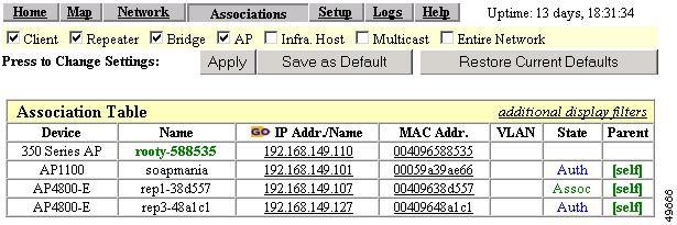
The management system's Association Table page lists all the devices, both wireless and wired to the root LAN, of which the access point is aware. Figure 9-1 shows an example of the Association Table page.
Figure 9-1 Association Table Page
Click the Association link at the top of any main management system page to go to the Association Table.
Note
Browsing to Network Devices
To browse to a device's browser-based interface, click the device's IP address in the IP Addr. column. The home page of the device's management system appears. Cisco Aironet access points, bridges, and workgroup bridges have browser-based interfaces, and many servers and printers have them, also.
If the device does not have a browser-based interface, click the device's MAC address in the MAC Addr. column. A Station page appears for the device, displaying the information the access point knows about the device, including the device's identity and statistics on traffic to and from the device. Some devices, such as PC card client adapters, do not have browser-based interfaces.
Setting the Display Options
You use the display options to select the device types to be listed in the table. The default selections list only the access point and any devices with which it is associated. To change the selections, click a display option and then click Apply.
To modify the table further, click additional display filters, which is a link to the Association Table Filters page. You use the Association Table Filters page to select the columns of information that appear in the Association Table and the order in which devices are listed.
For more information on customizing the Association Table display, read the "Association Table Display Setup" section.
Using Station Pages
Click a device's MAC address in the Association Table's MAC Addr. column to display a Station page for the device.
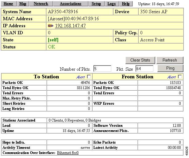
Station pages provide an overview of a network device's status and data traffic history. The information on a Station page depends on the device type; a Station page for an access point, for example, contains different information than the Station page for a PC card client adapter.
You can also use the Station page to perform pings and link tests for network devices. Figure 9-2 shows a sample Station page for a PC card client adapter.
Figure 9-2 Station Page
Information on Station Pages
Station Identification and Status
The yellow table at the top of the Station page lists the following information:
•
•
•
•
When you click the IP address link, the browser attempts to display the device's home page. Cisco Aironet access points, bridges, and workgroup bridges have browser-based interfaces, and many servers and printers have them also.
•
Policy Grp.—A group of filters specifically designed to allow or deny certain types of traffic to or from the access point.
•
–
–
–
–
•
–
–
–
–
–
–
•
–
–
–
–
–
–
–
–
To Station Information
Fields in the To Station column in the second table on the Station page contain the following information:
•
•
•
•
•
•
•
From Station Information
Fields in the To Station column contain the following information:
•
•
•
•
•
Rate, Signal, and Status Information
The table under the To and From Station table lists rate, signal, and status information for the device.
Data rate and signal quality information appears on Station pages for client devices. On Station pages for access points, this area shows network information such as system uptime.
•
•
•
•
•
•
The following four fields appear only on the Station page for an access point:
•
•
•
•
Hops and Timing Information
The table at the bottom of the Station page lists information on the chain of devices, if any, between the device and the wired LAN, on the monitoring timeout for the device, and on the time of the most recent system activity.
•
•
•
•
•
Performing Pings and Link Tests
Use the ping and link test buttons to perform pings and link tests on the device. If the device is associated to the access point through which you reached the Station page, the link test button and packet fields appear. If the device is not associated with the access point, only the ping button and packet fields appear.
Performing a Ping
Follow these steps to ping the device described on the Station page:
Step 1
Step 2
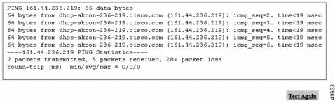
The ping runs using the values in the Number of Pkts. and Pkt. Size fields, and a ping window appears listing the test results. To run the ping again, click Test Again. Figure 9-3 shows a ping window.
Figure 9-3 Ping Window
Performing a Link Test
Follow these steps to perform a link test between the access point and the device described on the Station page:
Step 1
Step 2
The link test runs using the values in the Number of Pkts. and Pkt. Size fields.
Note
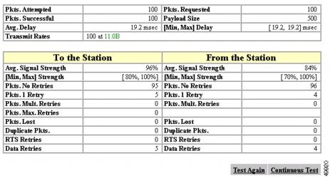
A results window appears listing the test results. To run the test again, click Test Again. To run a continuous link test, click Continuous Test. Figure 9-4 shows a link test results window.
Figure 9-4 Link Test Results Window
Clearing and Updating Statistics
Use the Clear Stats and Refresh buttons to clear and update the Station page statistics.
•
•
Deauthenticating and Disassociating Client Devices
Use the Deauthenticate and Disassociate buttons to deauthenticate and disassociate the client device from the access point. These buttons appear only on Station pages for devices that are associated with the access point, and only users with administrator capability can operate them.
•
•
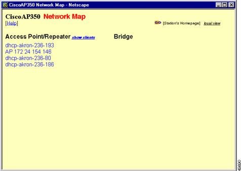
Using the Network Map Window
To open the Network Map window, click Map at the top of any management system page. (See the "Using the Network Map Window" section for information about the Map page.) When the Map window appears, click Network Map.
You use the Network Map window to open a new browser window displaying information for any device on your wireless network. Unlike the Association Table, the Network Map window does not list wired devices on your LAN. Figure 9-5 shows the Network Map window.
Note
Figure 9-5 Network Map Window
Click the name of a wireless device to open a new browser window displaying a Station page displaying the access point's local information for that device. Click Go beside the device name to open a new browser window displaying that device's home page, if available. Some devices, such as PC card clients, do not have browser-based interfaces.
Click show clients to display all the wireless client devices on your network. The client names appear under the access point or bridge with which they are associated. If clients are displayed, click hide clients to display only non-client devices.
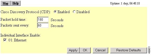
Using Cisco Discovery Protocol
Cisco Discovery Protocol (CDP) is a device-discovery protocol that runs on all Cisco network equipment. Each device sends identifying messages to a multicast address, and each device monitors the messages sent by other devices. Information in CDP packets is used in network management software such as CiscoWorks2000.
Use the CDP Setup page to adjust the access point's CDP settings. CDP is enabled by default. Figure 9-6 shows the CDP Setup page.
Figure 9-6 CDP Setup Page
Follow this link path to reach the CDP Setup page:
1.
2.
3.
Settings on the CDP Setup Page
The CDP Setup page contains the following settings:
•
•
•
•
MIB for CDP
A MIB file is available for use with CDP. The filename is CISCO-CDP-MIB.my, and you can download the MIB at the following URL:
http://www.cisco.com/public/mibs
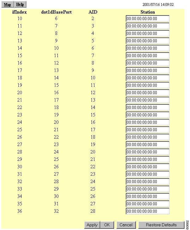
Assigning Network Ports
Use the Port Assignments page to assign a specific network port to a repeater access point or to a non-root bridge. When you assign specific ports, your network topology remains constant even when devices reboot. Figure 9-7 shows the Port Assignments page.
Figure 9-7 Port Assignments Page
Follow this link path to reach the Port Assignments page:
1.
2.
Settings on the Port Assignments Page
The Port Assignments page displays the following information:
•
•
•
•
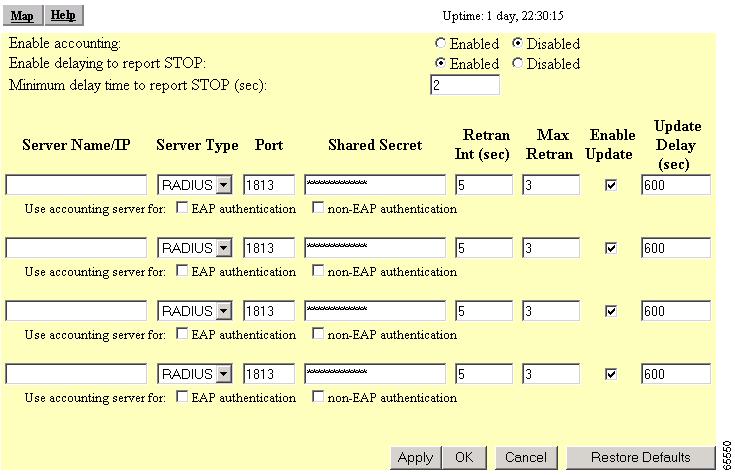
Enabling Wireless Network Accounting
You can enable accounting on the access point to send network accounting information about wireless client devices to a RADIUS server on your network. Cisco Secure ACS writes accounting records to a log file or to a database daily. Consult the Cisco Secure ACS 2.6 for Windows 2000/NT Servers User Guide for instructions on viewing and downloading the log or database:
http://www.cisco.com/univercd/cc/td/doc/product/access/acs_soft/csacs4nt/csnt26/index.htm
If you have a UNIX server, use this URL to browse to the CiscoSecure ACS 2.3 for UNIX User Guide:
http://www.cisco.com/univercd/cc/td/doc/product/access/acs_soft/cs_unx/csu23ug/index.htm
Use the Accounting Setup page to enable and set up accounting on the access point. Figure 9-8 shows the Accounting Setup page.
Figure 9-8 Accounting Setup Page
Follow this link path to reach the Accounting Setup page:
1.
2.
Settings on the Accounting Setup Page
The Accounting Setup page contains these settings:
•
•
•
•
•
•
•
•
•
•
•
•
Accounting Attributes
Table 9-1 lists the accounting attributes the access point sends to the accounting server.