-
Cisco Aironet Access Point Software Configuration Guide for VxWorks
-
Preface
-
Overview
-
Using the Management Interfaces
-
Configuring the Radio and Basic Settings
-
Configuring VLANs
-
Configuring Filters and Quality of Service
-
Configuring Proxy Mobile IP
-
Configuring Other Settings
-
Security Setup
-
Network Management
-
Managing Firmware and Configurations
-
Management System Setup
-
Special Configurations
-
Diagnostics and Troubleshooting
-
Appendix A - Protocol Filter Lists
-
Appendix B - Channels, Power Levels, and Antenna Gains
-
Appendix C - Event Log Messages
-
Index
-
 Feedback
Table Of Contents
Settings on the VLAN Setup page
Maximum Number of Enabled VLAN IDs
Single VLAN ID which allows Unencrypted packets
Optionally allow Encrypted packets on the unencrypted VLAN
RADIUS-Based VLAN Access Control
Criteria for Deploying Wireless VLANs
A Wireless VLAN Deployment Example
Using the Configuration Screens
Obtaining and Recording VLAN ID and Setup Information
Creating and Configuring VLANs on the Access Point
Creating the Full- and Part-Time VLANs
Creating and Configuring the SSIDs
Enabling VLAN (802.1Q) Tagging and Identifying the Native VLAN
Creating an SSID for Infrastructure Devices
Guidelines for Wireless VLAN Deployment
Configuring VLANs
This chapter describes VLANs and provides information about configuring them on an access point. The chapter guides you through the process for configuring a typical example VLAN deployment.
This chapter contains the following sections:
•
RADIUS-Based VLAN Access Control
•
•
•
Entering VLAN Information
To access the VLAN setup page (see Figure 4-1). click VLAN in the Associations section of the Setup page. You can also access the page from the AP Radio Advanced page in the Network Ports section of the Setup page.
Figure 4-1 VLAN Setup Page
Follow this link path to reach the VLAN Setup page:
1.
2.
Settings on the VLAN Setup page
The VLAN setup page contains the following settings:
•
•
•
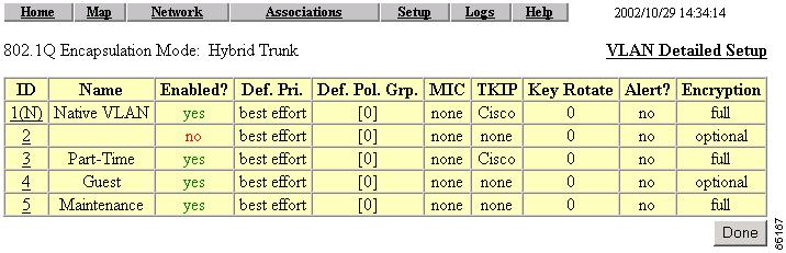
VLAN Summary Status Link
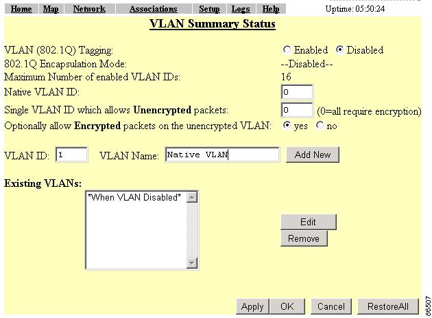
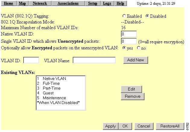
Clicking this link takes you to a page containing a listing of existing VLANs on the access point. The list provides you with configuration information for each VLAN. Figure 4-2 shows a typical VLAN Summary Status page.
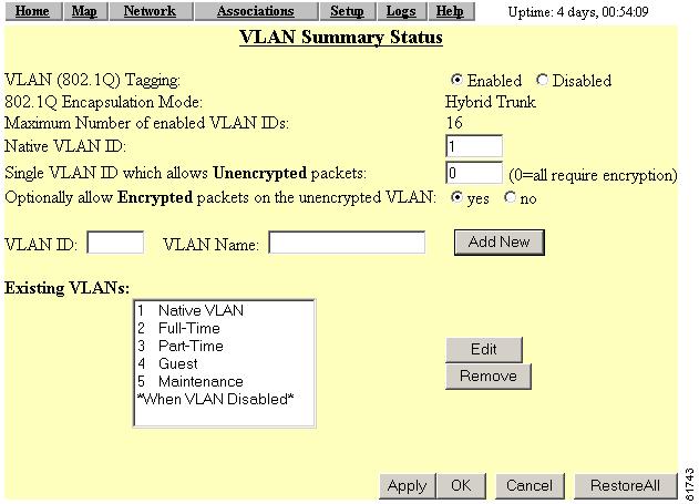
Figure 4-2 VLAN Summary Status Page
VLAN (802.1Q) Tagging
Determines whether the IEEE 802.1Q protocol is used to tag VLAN packets. IEEE 802.1Q protocol is used to connect multiple switches and routers and for defining VLAN topologies. This setting is user configurable.
Early 340 series access points are incompatible with VLAN tagging. Early versions of the 340 series access point can set up VLANs, but clients on non-native VLANs cannot transmit and receive large packets because early 340 series access points were limited to a packet data length of 1500 bytes.
You can identify an affected access point by browsing to the Ethernet Identification page and checking the Maximum Packet Data Length parameter. If it is 1500, the failure will occur.
If you have an early 340 series access point on your network, you can eliminate the problem by setting the Maximum Packet Data Length parameter for all other devices to 1400 bytes.
802.1Q Encapsulation Mode
A status setting that indicates whether or not IEEE 802.1Q tagging is in use. This field always displays disabled unless the following conditions are met:
•
•
Maximum Number of Enabled VLAN IDs
A status setting that provides the maximum number of VLANs that can reside on the access point. This setting is for information only and is not configurable.
Native VLAN ID
Specifies the identification number of the access point's native VLAN. This configurable setting must agree with the native VLAN ID setting on the switch.
Single VLAN ID which allows Unencrypted packets
Identifies the number of the VLAN on which unencrypted packets can pass between the access point and the switch. This setting is configurable.
Optionally allow Encrypted packets on the unencrypted VLAN
Determines whether the access point passes encrypted packets on an unencrypted VLAN. This setting permits a client device to associate to the access point allowing both WEP and non-WEP associations.
VLAN ID
A unique number that identifies a VLAN. This number must match VLANs set on the switch. The setting is configured by the user.
VLAN Name
A unique name for a VLAN configured on the access point. This setting is configured by the user. The VLAN name is for information only and is not used by the switch or access point as a parameter for determining the destination of data.
Existing VLANs
A list of successfully configured VLANs on the access point. As the user configures VLANs, they appear in this list by ID number and name. From this list, you can edit or remove a VLAN.
VLAN Security Policy
You can define a security policy for each VLAN on the access point. This enables you to define the appropriate restrictions for each VLAN you configure. The following parameters can be configured on the wireless SSID page:
•
•
•
•
•
•
•
•
The following parameters can be configured on the VLAN ID page:
•
•
•
•
•
•
•
•
Note
Table 4-1 lists the SSID and VLAN ID configuration parameters.
Broadcast Domain Segmentation
All Layer 2 broadcast and multicast messages are propagated over the air so that each WLAN client receives broadcast and multicast traffic belonging to different VLANs. A wired client receives Layer 2 broadcast and multicast traffic only for its own VLAN. Therefore, a unique broadcast/multicast encryption key is used to segment the Layer 2 broadcast domains on the wireless LAN. The unique encryption key must be configured during initial VLAN setup. If broadcast key rotation is enabled, this encryption key is generated dynamically and delivered to WLAN clients in IEEE 802.1x messages.
The requirement to segment broadcast domains on the wireless side restricts the use of unencrypted VLAN per ESS. A maximum of one VLAN can be unencrypted per WLAN ESS. The behavior of a WLAN client on an encrypted VLAN should be to discard unencrypted Layer 2 broadcast or multicast traffic.
Native VLAN Configuration
The native VLAN setting on the access point must match the native VLAN of the wired trunk. Also, the access point receives and communicates using the Inter-Access Point Protocol (IAPP) with other access points in the same wireless LAN ESS using the native VLAN. Therefore, it is a requirement that all access points in an ESS must use the same native VLAN ID. Furthermore, all Telnet and http management traffic as well as the RADIUS traffic is routed to the access point through the native VLAN. It is recommended that you restrict user access to the native (default) VLAN of the access points through the use of Layer 3 ACLs and policies on the wired infrastructure side.
You may or may not wish to map the native VLAN of the access point to an SSID (for example, to the wireless ESS). Scenarios where the native VLAN must be mapped to an SSID are as follows:
•
•
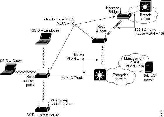
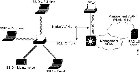
In these scenarios, Cisco recommends that you configure an infrastructure SSID for each access point. Figure 4-3 illustrates combined deployment of infrastructure devices along with noninfrastructure devices in an enterprise LAN. As the figure shows, the native VLAN of the access point is mapped to the infrastructure SSID. WEP encryption along with TKIP (at least per packet key hashing) should be turned on for the infrastructure SSID. Cisco also recommends that you configure a secondary SSID as the infrastructure SSID. The concepts of primary and secondary SSIDs are explained in the next section.
Figure 4-3 Deployment of Infrastructure and Non infrastructure Devices
Primary and Secondary SSIDs
When multiple wireless VLANs are enabled on an access point or bridge, multiple SSIDs are created. Each SSID maps to a default VLAN ID on the wireless side. IEEE 802.11 specifications require that only one SSID be broadcast in the beacons, so you must define a primary SSID to be broadcast in the IEEE 802.11 beacon management frames. All other SSIDs are secondary SSIDs and are not broadcast in the beacon management frames.
If a client or infrastructure device (such as a workgroup bridge) sends a probe request with a secondary SSID, the access point or bridge responds with a probe response with a secondary SSID.
You can map the primary SSID to the VLAN ID on the wired infrastructure in different ways. For example, in an enterprise rollout scenario, the primary SSID could be mapped to the unencrypted VLAN on the wired side to provide guest VLAN access.
RADIUS-Based VLAN Access Control
You may want to impose RADIUS-based VLAN access control. For example, if the WLAN setup is such that all VLANs use IEEE 802.1x and similar authentication mechanisms for WLAN user access, the user can hop from one VLAN to another by changing the SSID and successfully authenticating to the access point. However, this process may not be ideal if the wireless user is to be confined to a particular VLAN.
There are two ways to implement RADIUS-based VLAN access control on the access point:
1.
2.
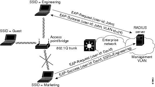
Figure 4-4 illustrates both RADIUS-based VLAN access control methods. In the figure, both Engineering and Marketing VLANs are configured to allow only IEEE 802.1x authentication (LEAP, EAP-TLS, PEAP, etc.). When user John uses the Engineering SSID to access the WLAN, the RADIUS server maps John to VLAN ID 24, which may or may not be the default VLAN ID mapping for the Engineering SSID. Using this method, a user can be mapped to a fixed wired VLAN throughout an enterprise network.
Figure 4-4 also shows an example for RADIUS-based SSID access control. In the figure, David uses the Marketing SSID to access the WLAN however, the permitted SSID list sent back by the RADIUS server allows David to access only the Engineering SSID and the access point disassociates him from the WLAN. Using RADIUS-based SSID access, a user can be given access to one or multiple SSIDs throughout the enterprise network.
Figure 4-4 RADIUS-Based VLAN Access Control
RADIUS user attributes used for VLAN ID assignment are:
•
•
•
The Cisco IOS/PIX/RADIUS Attribute (009\001 cisco-av-pair) user attribute is used for SSID control. For example, this attribute allows a user to access the WLAN using the Engineering and Marketing SSIDs only.
Criteria for Deploying Wireless VLANs
You should evaluate the need for deploying wireless VLANs in their own environment. Cisco recommends that you review the VLAN deployment rules and policies before considering wireless VLAN deployment and that you use similar policies to extend wired VLANs to the wireless LAN. This section details criteria for wireless VLAN deployment, a summary of rules for wireless LAN (WLAN) VLAN deployment, and best practices to use on the wired infrastructure side when you deploy wireless VLANs.
Criteria for wireless VLAN deployment are likely to be different for each scenario. The following are the most likely criteria:
•
–
–
•
–
–
–
•
–
–
–
You should consider the following implementation criteria before deploying wireless VLANs:
•
•
•
•
Based on these criteria, you could choose to deploy wireless VLANs using the following strategies:
•
•
A Wireless VLAN Deployment Example
This section outlines a typical use of wireless VLANs. For the example, assume your company, XYZ, determines the need for wireless LANs in its network. Following the guidelines in the previous sections, your findings are as follows:
•
•
•
•
•
•
•
Using the information above, you could deploy wireless VLANs by creating four wireless VLANs as follows:
•
•
Note
•
•
Figure 4-5 shows the wireless VLAN deployment scenario described above.
Figure 4-5 Wireless VLAN Deployment Example
Using the Configuration Screens
Using the example outlined above, this section describes how to use the configuration screens to configure VLANs on your access point.
To create and enable VLANs on your access point you must complete the following procedures:
1.
2.
3.
4.
5.
Obtaining and Recording VLAN ID and Setup Information
See your organization's network administrator to obtain the information you need to create VLANs on your access point. For this example, Table 4-2 lists the information required to configure the VLANs on the access point.
Creating and Configuring VLANs on the Access Point
For this example, you will create 5 VLANs using the information in Table 3-2.
Note
Creating the Native VLAN
You must create and identify a native VLAN before the access point can connect to the trunk and communicate with the switch. Follow these steps to create the native VLAN.
Step 1
Step 2
Step 3
Figure 4-6 VLAN Setup Page
Step 4
Step 5
Step 6
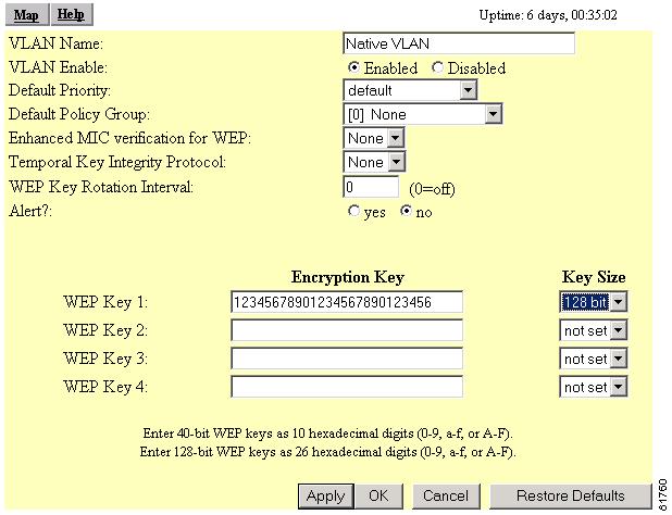
Figure 4-7 VLAN ID #1 Setup Page
Step 7
a.
b.
c.
d.
e.
f.
g.
h.
Step 8
Creating the Full- and Part-Time VLANs
The full- and part-time VLANs are essentially the same except for their names and SSIDs. Follow these steps to create these VLANs.
Step 1
a.
b.
c.
d.
e.
f.
Step 2
Step 3
a.
b.
c.
d.
e.
f.
g.
h.
i.
j.
Step 4
Step 5
a.
b.
Step 6
Step 7
Step 8
Creating the Guest VLAN
Step 1
a.
b.
c.
d.
e.
f.
Step 2
Step 3
a.
a.
b.
c.
d.
e.
f.
g.
h.
Note
Step 4
Step 5
Creating the Maintenance VLAN
Step 6
a.
a.
b.
c.
d.
e.
Step 7
Step 8
a.
b.
c.
d.
e.
f.
g.
h.
i.
Step 9
Step 10
Creating and Configuring the SSIDs
After you create the VLANs for your access point, you create the SSIDs to which the VLANs associate. Follow these steps to create the SSIDs.
Step 1
Step 2
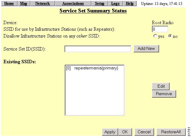
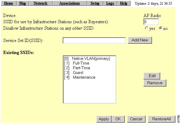
Figure 4-8 AP Radio Service Sets Page
Step 3
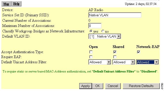
Figure 4-9 AP Radio Primary SSID Page
Step 4
a.
b.
c.
Note
d.
e.
f.
Step 5
Step 6
Step 7
a.
b.
Step 8
Step 9
Step 10
Step 11
Step 12
Step 13
Step 14
Step 15
Step 16
Step 17
Step 18
Note
Step 19
Enabling VLAN (802.1Q) Tagging and Identifying the Native VLAN
When you have finished creating and configuring the VLANs and their associated SSIDs, you must enable VLAN IEEE 802.1Q tagging to make them operational. You must also identify the native VLAN. Follow these steps to enable VLAN IEEE 802.1Q tagging and identify the native VLAN.
Step 1
Figure 4-10 VLAN Setup Page
Step 2
Step 3
Step 4
Figure 4-11 AP Radio Service Sets Page
Step 5
Step 6
Step 7
Step 8
Step 9
Your wireless network is ready to operate using the VLANs you have created.
Creating an SSID for Infrastructure Devices
You must map the native VLAN to an SSID for infrastructure devices (such as workgroup bridges and repeaters) so that they can communicate in the VLAN environment. Follow these steps.
Step 1
Step 2
Step 3
Step 4
Guidelines for Wireless VLAN Deployment
You may want to consider these guidelines before you deploy wireless VLANs on your network:
•
•
•
•
•
•
•
•
•
•
•
•
•
•
•
Wireless LAN security policies can be mapped to the wired LAN switches and routers.