-
Cisco Aironet Access Point Software Configuration Guide for VxWorks
-
Preface
-
Overview
-
Using the Management Interfaces
-
Configuring the Radio and Basic Settings
-
Configuring VLANs
-
Configuring Filters and Quality of Service
-
Configuring Proxy Mobile IP
-
Configuring Other Settings
-
Security Setup
-
Network Management
-
Managing Firmware and Configurations
-
Management System Setup
-
Special Configurations
-
Diagnostics and Troubleshooting
-
Appendix A - Protocol Filter Lists
-
Appendix B - Channels, Power Levels, and Antenna Gains
-
Appendix C - Event Log Messages
-
Index
-
 Feedback
Table Of Contents
Configuring Filters and Quality of Service
Entering Information on the Quality of Service Setup Page
Settings on the Quality of Service Setup Page
A Wireless QoS Deployment Example
WEP Not Set on the Wireless Phone
Configuring Filters and Quality of Service
This chapter provides information and configuration procedures for setting up filters. The chapter also provides information and procedures for setting up QoS using filters you create.
This chapter contains the following sections:
•
A Wireless QoS Deployment Example
Filter Setup
This section describes how to set up filtering to control the flow of data through the access point. You can filter data based on protocols and MAC addresses. Each type of filtering is explained in the following sections:
Protocol Filtering
Protocol filters prevent or allow the use of specific protocols through the access point. You can set up individual protocol filters and enable each filter for one or more VLANs. You can filter protocols for wireless client devices, users on the wired LAN, or both. For example, an SNMP filter on the access point's radio port prevents wireless client devices from using SNMP with the access point but does not block SNMP access from the wired LAN.
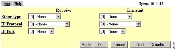
Use the Protocol Filters Setup page create and enable protocol filters for the access point's Ethernet port and for the access point's radio port. The Protocol Filters Setup page is shown on Figure 5-1.
Figure 5-1 Protocol Filters Setup Page
Follow this link path to reach the Protocol Filters Setup page:
1.
2.
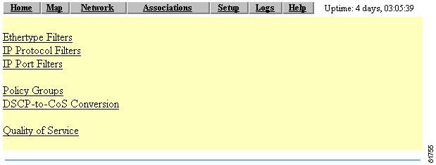
You can create protocol filters or view existing filters by clicking Filters in the Ethernet or Radio rows of the Network Ports section of the Setup page. The screens are identical except for the name. Figure 5-2 shows the Protocol Filters page.
Figure 5-2 Protocol Filters Page
Follow this link path to reach the AP Radio or Ethernet Protocol Filters page:
1.
2.
The left side of the Protocol Filters page contains links to the Ethertype Filters, the IP Protocol Filters, and the IP Port Filters pages.
Use the Protocol Filters pages to assign protocols to a filter set. Table A-1, Table A-2, and Table A-3 in Appendix B list the protocols available on each page.
Creating a Protocol Filter
Follow these steps to create a protocol filter:
Step 1
Step 2
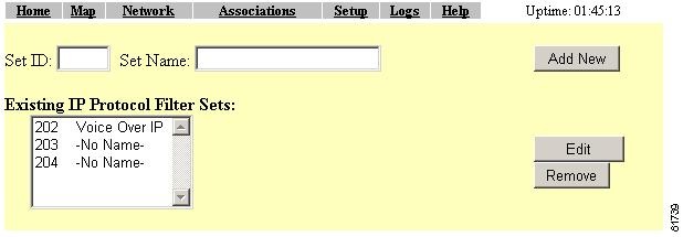
Figure 5-3 IP Protocol Filters Page
Step 3
Step 4
Step 5
Figure 5-4 Filter Set Page
Step 6
Step 7
Note
Step 8
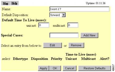
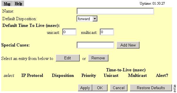
The Protocol Filter Set page appears. Figure 5-5 shows the Protocol Filter Set page.
Figure 5-5 Protocol Filter Set Page
Step 9
Step 10
•
•
•
•
•
•
•
Step 11
Note
Step 12
Step 13
To edit the protocol entry, type the protocol name in the Special Cases entry field or click the select button beside the entry and click Edit. To delete the protocol, type the protocol name in the Special Cases entry field or click the select button beside the entry and click Remove.
Step 14
Note
Enabling a Protocol Filter
Follow these steps to enable a protocol filter:
Step 1
Step 2
Step 3
Step 4
MAC Address Filtering
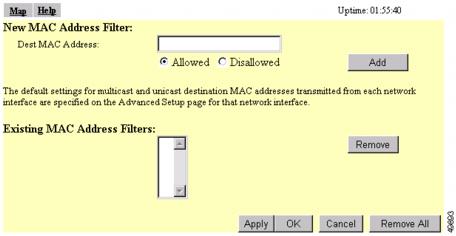
MAC address filters allow or disallow the forwarding of unicast and multicast packets either sent from or addressed to specific MAC addresses. You can create a filter that passes traffic to all MAC addresses except those you specify, or you can create a filter that blocks traffic to all MAC addresses except those you specify.
Note
Use the Address Filters page to create MAC address filters for the access point. Figure 5-6 shows the Address Filters page.
Figure 5-6 Address Filters Page
Follow this link path to reach the Address Filters page:
1.
2.
Creating a MAC Address Filter
Follow these steps to create a MAC address filter:
Step 1
Step 2
Note
Step 3
Step 4
Tip
Step 5
Step 6
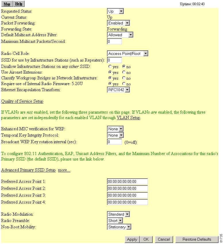
Figure 5-7 AP Radio Advanced Page
Step 7
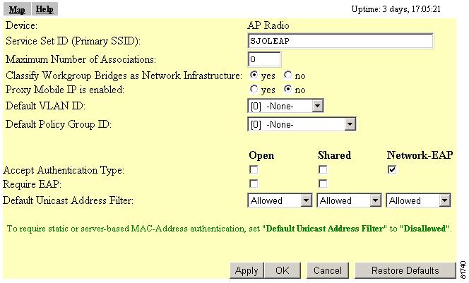
Figure 5-8 AP Radio Primary SSID Page
Select Open, Shared Key, or Network-EAP to set the authentications the access point recognizes. See the "Security Overview" section for a description of authentication types.
If you use open or shared authentication as well as EAP authentication, select Require EAP under Open or Shared to block client devices that are not using EAP from authenticating through the access point.
Unicast MAC address filters allow or disallow the forwarding of unicast packets sent to specific MAC addresses. You can create a filter that passes traffic to all MAC addresses except those you specify, or you can create a filter that blocks traffic to all MAC addresses except those you specify.
Read the "Setting Up MAC-Based Authentication" section for complete instructions on using MAC-based authentication on an authentication server. Read the "Creating a MAC Address Filter" section for complete instructions on setting up MAC address filters.
The drop-down menus for unicast address filters contain two options:
•
•
Select Disallowed for each authentication type that also uses MAC-based authentication.
Note
Step 8
If clients are not filtered immediately, click WARM RESTART SYSTEM NOW on the Manage System Configuration page to restart the access point. To reach the Manage System Configuration page, Click Cisco Services on the main Setup page and click Manage System Configuration on the Cisco Services Setup page.
Note
Note
QoS Configuration
You can assign QoS attributes to enable various devices on the network to communicate more effectively. The access point supports QoS for voice over IP (VoIP) telephones and downlink prioritized channel access for streaming audio and video traffic. This section describes how to configure the access point's QoS feature.
Entering Information on the Quality of Service Setup Page
Access the Quality of Service Setup page (see Figure 5-9) from the Summary Status page by clicking the Setup tab. From the Associations section of the Setup page, click Protocol Filters. This page is also accessed through the AP Radio Advanced page in the Network Ports section of the Setup page.
Figure 5-9 Quality of Service Setup Page
Follow this link path to reach the Quality of Service setup page:
1.
2.
3.
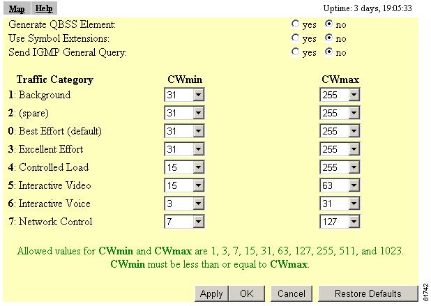
Settings on the Quality of Service Setup Page
The Quality of Service setup page contains the following settings:
Generate QBSS Element
Determines whether a QoS basic service set (QBSS) element is generated. The QBSS element determines the best access point with which to associate.
Use Symbol Extensions
Configures the access point to use Symbol Voice over IP (VoIP) phones. When this setting is enabled, the access point uses the Symbol Phone Support protocol. This protocol identifies Symbol handsets and classifies traffic for them as interactive voice.
Send IGMP General Query
Configures the access point to perform IP multicast filtering on behalf of its clients. When Internet Group Membership Protocol (IGMP) snooping is enabled on a switch, and a client roams from one access point to another, the multicast session is dropped. Enabling this feature causes the access point to send a general IGMP query to the network infrastructure on behalf of the client every time it associates or reassociates to the access point. By doing so, the multicast stream is maintained for the client as it roams.
Traffic Category
Traffic category identifies a type of traffic in which data processed by the access point is categorized. There are seven categories:
•
•
•
•
•
•
•
•
Each category is assigned a minimum contention window (CWmin) value and a maximum contention window (CWmax) value. Allowed values for CWmin and CWmax are 1, 3, 7, 15, 31, 63, 127, 255, 511, and 1023.
Note
Applying QoS
You can apply QoS to specific traffic handled by the access point in a number of ways:
•
•
•
•
•
By Station
The access point can prioritize traffic based upon a WLAN client identifying itself as a particular client type that requires a particular traffic classification.
The best example of this is the negotiations between the access point and a Symbol VoIP WLAN handset. A protocol has been defined by Symbol that allows the handset to be identified by the access point and given interactive voice classification. Follow these steps to enable this feature.
Step 1
Step 2
Figure 5-10 Protocol Filters Setup Page
Step 3
Figure 5-11 AP Radio Quality of Service Page
Step 4
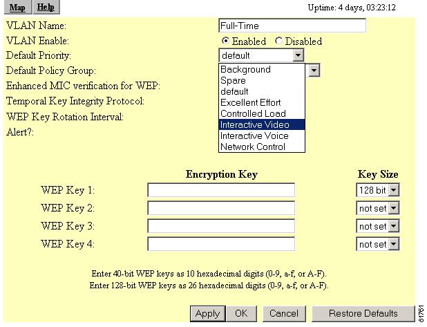
By VLAN
The default priority of a VLAN can be set, and the access point uses this setting for all traffic on that VLAN except when overridden by a filter setting. This filter setting is applied through the policy group on the VLAN.
Follow these steps to set up a VLANs QoS default priority.
Step 1
Step 2
Figure 5-12 VLAN ID page
Step 3
Step 4
Step 5
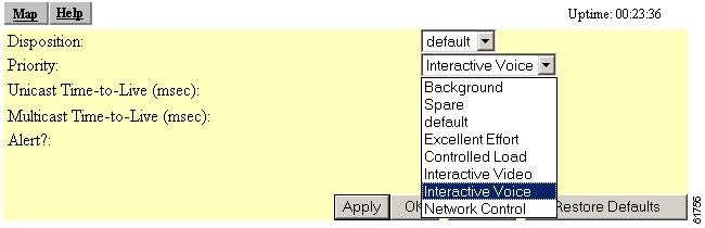
By Filter
Access point and bridge filters already allow the classification of traffic based upon Ethertype, Internet Protocol, or IP Port. An example of a filter classifying traffic is shown on Figure 5-13.
Figure 5-13 Filters Priority Setting
The filters can be applied on interfaces or as a part of a VLAN policy group.
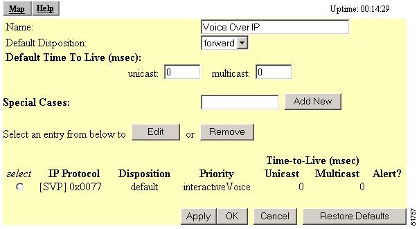
The access point has a default filter to classify all Spectralink voice traffic with voice priority. You do not have to enable this filter, but you can modify the filter and apply it to a specific VLAN or interface.
Note
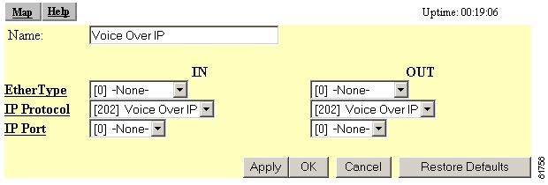
A typical Spectralink filter configuration is shown on Figure 5-14.
Figure 5-14 Spectralink Filter Configuration
Figure 5-15 shows how the Spectralink filter is applied.
Figure 5-15 Applying the Spectralink Filter
By CoS Value
Traffic that comes to the access point over an Ethernet trunk is already classified by its Class of Service (CoS) settings. The classification is applied unless changed by one of the methods described above.
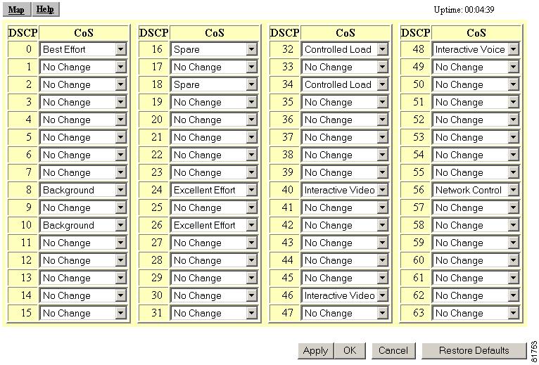
By DSCP Value
The differentiated services code point (DSCP) values in the IP packets can be used to classify the traffic based on the DSCP-to-CoS mappings shown in Figure 5-16.
Figure 5-16 DSCP-to-CoS Conversion
Follow these steps to access the DSCP-to-CoS Conversion page.
Step 1
Step 2
Step 3
A Wireless QoS Deployment Example
This section outlines a typical use for deploying QoS on a wireless LAN: configuring the access point to properly prioritize an 802.11b wireless phone using a VLAN.
Before discussing the steps involved to configure this QoS scenario, it is assumed that you have configured and enabled VLANs on the access point and that all downstream interactive voice configurations are made to other infrastructure devices and applicable applications on the wired LAN, such as switches, routers, DHCP servers, Call Manager, etc.
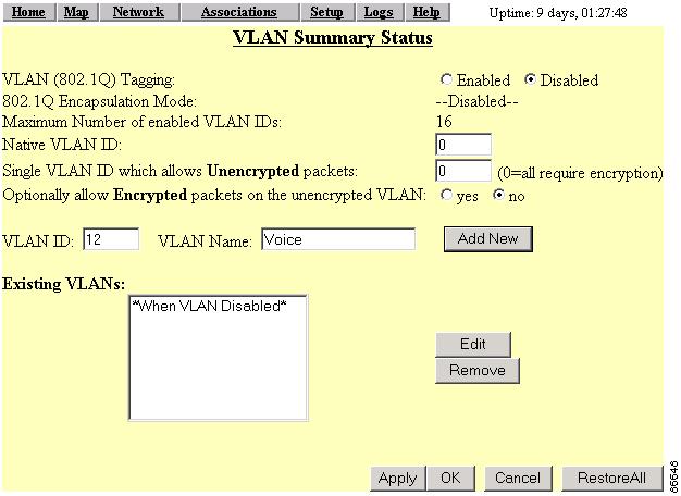
In this example, we create a VLAN dedicated to interactive voice. Its ID is 12 and its name is Voice. An SSID called Voice is created to handle the interactive voice traffic on the access point.
Note
Follow these steps to configure the access point:
Step 1
Step 2
Step 3
Step 4
Figure 5-17 VLAN Setup page
Step 5
Step 6
Step 7
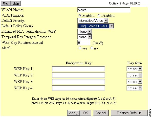
Figure 5-18 VLAN ID #xx page
Note
If your wireless phone has a WEP key set, go the next section. If a WEP key is not set, go to the "WEP Not Set on the Wireless Phone" section.
WEP Set on the Wireless Phone
If WEP is set on your wireless phone, you must set an identical WEP key for the interactive voice VLAN. Follow these steps to set the WEP key.
Step 1
Step 2
Step 3
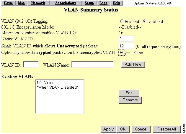
WEP Not Set on the Wireless Phone
If a WEP key is not set on the wireless phone, you must complete the configuration by following these steps:
Step 1
Step 2
Step 3
Figure 5-19 VLAN Setup page
Step 4
Step 5
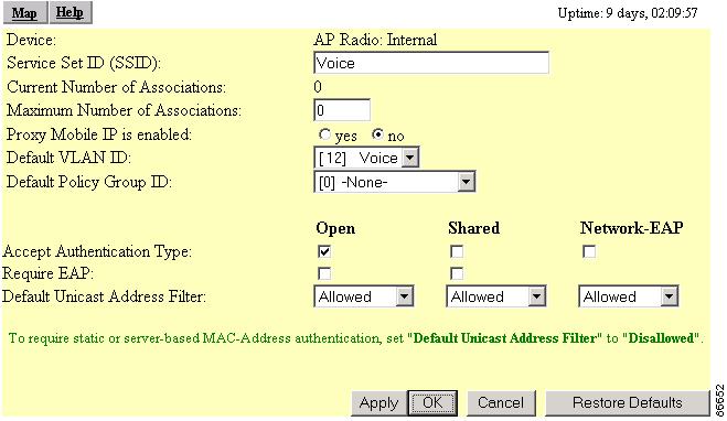
Step 6
Figure 5-20 AP Radio: Internal Service Sets page
Step 7
Step 8
Figure 5-21 AP Radio: Internal Service Sets page
Step 9
Step 10
Your configuration is complete.