-
Cisco MDS 9000 Family CLI Configuration Guide, Release 3.3(3)
-
Index
-
New and Changed Information
-
Preface
- Getting Started
- Installation and Switch Management
- Switch Configuration
-
Fabric Configuration
-
Configuring and Managing VSANs
-
SAN Device Virtualization
-
Creating Dynamic VSANs
-
Configuring Inter-VSAN Routing
-
Distributing Device Alias Services
-
Configuring Fibre Channel Routing Services and Protocols
-
Managing FLOGI, Name Server, FDMI, and RSCN Databases
-
Discovering SCSI Targets
-
Configuring FICON
-
Advanced Features and Concepts
-
Configuring and Managing Zones
-
-
Security
-
Configuring FIPS
-
Configuring Users and Common Roles
-
Configuring SNMP
-
Configuring RADIUS and TACACS+
-
Configuring IPv4 and IPv6 Access Control Lists
-
Configuring Certificate Authorities and Digital Certificates
-
Configuring IPsec Network Security
-
Configuring FC-SP and DHCHAP
-
Configuring Port Security
-
Configuring Fabric Binding
-
- IP Services
- Intelligent Storage Services
- Network and Switch Monitoring
- Traffic Management
- Troubleshooting
-
Configuration Limits for Cisco MDS SAN-OS Release 3.x
-
 Feedback
Table Of Contents
About iSCSI Configuration Limits
Presenting Fibre Channel Targets as iSCSI Targets
iSCSI Virtual Target Configuration Examples
Presenting iSCSI Hosts as Virtual Fibre Channel Hosts
Example of VSAN Membership for iSCSI Devices
Advanced VSAN Membership for iSCSI Hosts
Fibre Channel Zoning-Based Access Control
Restricting iSCSI Initiator Authentication
iSCSI Immediate Data and Unsolicited Data Features
iSCSI Interface Advanced Features
Displaying Proxy Initiator Information
Displaying Global iSCSI Information
Displaying iSCSI Virtual Targets
Displaying iSCSI User Information
About iSLB Configuration Limits
iSLB Configuration Prerequisites
Configuring iSLB Initiator Names or IP Addresses
Assigning WWNs to iSLB Initiators
Making the Dynamic iSLB Initiator WWN Mapping Static
Assigning VSAN Membership for iSLB Initiators
Configuring Metric for Load Balancing
Verifying iSLB Initiator Configuration
Configuring iSLB Initiator Targets
Configuring and Activating Zones for iSLB Initiators and Initiator Targets
Configuring iSLB Session Authentication
Verifying iSLB Authentication Configuration
About Load Balancing Using VRRP
Changing iSCSI Interface Parameters and the Impact on Load Balancing
VRRP Load Balancing Algorithm For Selecting Gigabit Ethernet Interfaces
Configuring Load Balancing Using VRRP
Enabling VRRP for Load Balancing
Verifying iSLB VRRP Load Balancing Configuration
Displaying iSLB VRRP Information
About iSLB Configuration Distribution Using CFS
Distributing the iSLB Configuration Using CFS
Enabling iSLB Configuration Distribution
Committing Changes to the Fabric
Displaying Pending iSLB Configuration Changes
Displaying iSLB CFS Distribution Session Status
Displaying iSLB CFS Merge Status
iSCSI High Availability with Host Running Multi-Path Software
iSCSI HA with Host Not Having Any Multi-Path Software
LUN Trespass for Storage Port Failover
Multiple IPS Ports Connected to the Same IP Network
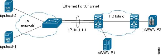
Ethernet PortChannel-Based High Availability
iSCSI Authentication Setup Guidelines and Scenarios
CHAP with Local Password Database
CHAP with External RADIUS Server
iSCSI Transparent Mode Initiator
Target Storage Device Requiring LUN Mapping
About iSNS Client Functionality
Creating an iSNS Client Profile
Verifying iSNS Client Configuration
About iSNS Server Functionality
iSNS Configuration Distribution
Configuring the ESI Retry Count
Configuring the Registration Period
iSNS Client Registration and Deregistration
Verifying the iSNS Server Configuration
Configuring iSNS Cloud Discovery
Initiating On-Demand iSNS Cloud Discovery
Configuring Automatic iSNS Cloud Discovery
Verifying Automatic iSNS Cloud Discovery Configuration
Configuring iSNS Cloud Discovery Distribution
Configuring iSNS Cloud Discovery Message Types
Verifying Cloud Discovery Status
Verifying Cloud Discovery Membership
Displaying Cloud Discovery Statistics
Configuring iSCSI
Cisco MDS 9000 Family IP storage (IPS) services extend the reach of Fibre Channel SANs by using open-standard, IP-based technology. The switch allows IP hosts to access Fibre Channel storage using the iSCSI protocol.
Note
The iSCSI feature is specific to the IPS module and is available in Cisco MDS 9200 Switches or Cisco MDS 9500 Directors.
The Cisco MDS 9216i switch and the 14/2 Multiprotocol Services (MPS-14/2) module also allow you to use Fibre Channel, FCIP, and iSCSI features. The MPS-14/2 module is available for use in any switch in the Cisco MDS 9200 Series or Cisco MDS 9500 Series.
Note
This chapter includes the following sections:
•
•
About iSCSI
Note
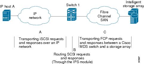
The iSCSI feature consists of routing iSCSI requests and responses between iSCSI hosts in an IP network and Fibre Channel storage devices in the Fibre Channel SAN that are accessible from any Fibre Channel interface of the Cisco MDS 9000 Family switch (see Figure 43-1).
Figure 43-1 Transporting iSCSI Requests and Responses for Transparent iSCSI Routing
Each iSCSI host that requires access to storage through the IPS module or MPS-14/2 module needs to have a compatible iSCSI driver installed. (The Cisco.com website at http://www.cisco.com/pcgi-bin/tablebuild.pl/sn5420-scsi provides a list of compatible drivers.) Using the iSCSI protocol, the iSCSI driver allows an iSCSI host to transport SCSI requests and responses over an IP network. From the host operating system perspective, the iSCSI driver appears to be a SCSI transport driver similar to a Fibre Channel driver in the host.
The IPS module or MPS-14/2 module provides transparent SCSI routing. IP hosts using the iSCSI protocol can transparently access targets on the Fibre Channel network. Figure 43-1 provides an example of a typical configuration of iSCSI hosts connected to an IPS module or MPS-14/2 module through the IP network access Fibre Channel storage on the Fibre Channel SAN.
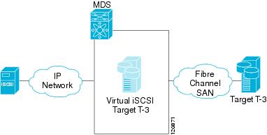
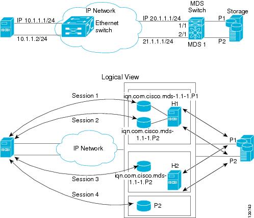
The IPS module or MPS-14/2 module create a separate iSCSI SAN view and Fibre Channel SAN view. For the iSCSI SAN view, the IPS module or MPS-14/2 module creates iSCSI virtual targets and then maps them to physical Fibre Channel targets available in the Fibre Channel SAN. They present the Fibre Channel targets to IP hosts as if the physical iSCSI targets were attached to the IP network (see Figure 43-2).
Figure 43-2 iSCSI SAN View—iSCSI virtual targets
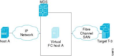
For the Fibre Channel SAN view, the IPS module or MPS-14/2 module presents iSCSI hosts as a virtual Fibre Channel host. The storage devices communicate with the virtual Fibre Channel host similar to communications performed with real Fibre Channel hosts (see Figure 43-3).
Figure 43-3 Fibre Channel SAN View—iSCSHI Host as an HBA
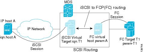
The IPS modules or MPS-14/2 modules transparently map the command between the iSCSI virtual target and the virtual Fibre Channel host (see Figure 43-4).
Figure 43-4 iSCSI to FCP (Fibre Channel) Routing
Routing SCSI from the IP host to the Fibre Channel storage device consists of the following main actions:
•
•
•
Note
Refer to the IETF standards for IP storage at http://www.ietf.org for information on the iSCSI protocol.
About iSCSI Configuration Limits
iSCSI configuration has the following limits:
•
•
•
•
•
Configuring iSCSI
This section describes how to configure iSCSI on the Cisco MDS 9000 Family switches.
This section includes the following sections:
•
•
•
•
Enabling iSCSI
To use the iSCSI feature, you must explicitly enable iSCSI on the required switches in the fabric. By default, this feature is disabled in all switches in the Cisco MDS 9000 Family.
To enable iSCSI on any participating switch, follow these steps:
Caution
Creating iSCSI Interfaces
Each physical Gigabit Ethernet interface on an IPS module or MPS-14/2 module can be used to translate and route iSCSI requests to Fibre Channel targets and responses in the opposite direction. To enable this capability, the corresponding iSCSI interface must be in an enabled state.
To enable iSCSI interfaces, follow these steps:
Step 1
switch# config terminalswitch(config)# interface gigabitethernet 2/1switch(config-if)# no shutdownswitch(config-if)# exitswitch(config)#Step 2
switch(config)# interface iscsi 2/1switch(config-if)# no shutdown
Presenting Fibre Channel Targets as iSCSI Targets
The IPS module or MPS-14/2 module presents physical Fibre Channel targets as iSCSI virtual targets, allowing them to be accessed by iSCSI hosts. It does this in one of two ways:
•
•
Static mapping should be used when iSCSI hosts should be restricted to subsets of LUs in the Fibre Channel targets and/or iSCSI access control is needed (see the "iSCSI Access Control" section). Also, static mapping allows the configuration of transparent failover if the LUs of the Fibre Channel targets are reachable by redundant Fibre Channel ports (see the "Transparent Target Failover" section).
Note
Dynamic Mapping
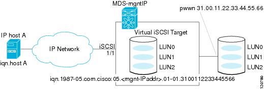
When you configure dynamic mapping the IPS module or MPS-14/2 module imports all Fibre Channel targets to the iSCSI domain and maps each physical Fibre Channel target port as one iSCSI target. That is, all LUs accessible through the physical storage target port are available as iSCSI LUs with the same LU number (LUN) as in the physical Fibre Channel target port.
The iSCSI target node name is created automatically using the iSCSI qualified name (IQN) format. The iSCSI qualified name is restricted to a maximum name length of 223 alphanumeric characters and a minimum length of 16 characters.
The IPS module or MPS-14/2 module creates an IQN formatted iSCSI target node name using the following conventions because the name must be unique in the SAN:
•
iqn.1987-05.com.cisco:05.<mgmt-ip-address>.<slot#>-<port#>-<sub-intf#>.<Target-pWWN>•
iqn.1987-05.com.cisco:05.vrrp-<vrrp-ID#>-<vrrp-IP-addr>.<Target-pWWN>•
iqn.1987-02.com.cisco:02.<mgmt-ip-address>.pc-<port-ch-sub-intf#>.<Target-pWWN>
Note
With this convention, each IPS port in a Cisco MDS 9000 Family switch creates a unique iSCSI target node name for the same Fibre Channel target port in the SAN.
For example, if an iSCSI target was created for a Fibre Channel target port with pWWN 31:00:11:22:33:44:55:66 and that pWWN contains LUN 0, LUN 1, and LUN 2, those LUNs would become available to an IP host through the iSCSI target node name iqn.1987-05.com.cisco:05. MDS_switch_management_IP_address.01-01.3100112233445566 (see Figure 43-5).
Figure 43-5 Dynamic Target Mapping
Note
To enable dynamic mapping of Fibre Channel targets into iSCSI, follow these steps:
Static Mapping
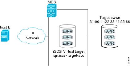
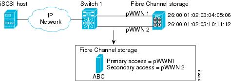
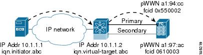
You can manually (statically) create an iSCSI target by assigning a user-defined unique iSCSI node name to it. The iSCSI qualified name is restricted to a minimum length of 16 characters and a maximum of 223 characters. A statically mapped iSCSI target can either map the whole Fibre Channel target port (all LUNs in the target port mapped to the iSCSI target), or it can contain one or more LUs from a Fibre Channel target port (see Figure 43-6).
Figure 43-6 Statically Mapped iSCSI Targets
Advertising Static iSCSI Targets
You can limit the Gigabit Ethernet interfaces through which static iSCSI targets are advertised. By default iSCSI targets are advertised on all Gigabit Ethernet interfaces, subinterfaces, PortChannel interfaces, and PortChannel subinterfaces.
To configure a specific interface that should advertise the iSCSI virtual target, follow these steps:
iSCSI Virtual Target Configuration Examples
This section provides three examples of iSCSI virtual target configurations.
Example 1
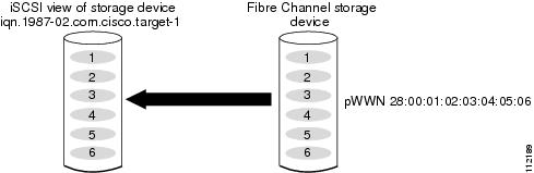
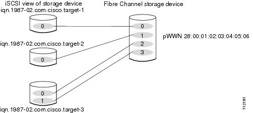
This example assigns the whole Fibre Channel target as an iSCSI virtual target. All LUNs that are part of the Fibre Channel target are available as part of the iSCSI target (see Figure 43-7).
Figure 43-7 Assigning iSCSI Node Names
iscsi virtual-target name iqn.1987-02.com.cisco.target-1pWWN 28:00:01:02:03:04:05:06Example 2
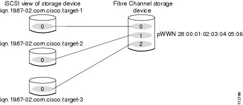
This example maps a subset of LUNs of a Fibre Channel target to three iSCSI virtual targets. Each iSCSI target only has one LUN (see Figure 43-8).
Figure 43-8 Mapping LUNs to an iSCSI Node Name
iscsi virtual-target name iqn.1987-02.com.cisco.target-1pWWN 28:00:01:02:03:04:05:06 fc-lun 0 iscsi-lun 0iscsi virtual-target name iqn.1987-02.com.cisco.target-2pWWN 28:00:01:02:03:04:05:06 fc-lun 1 iscsi-lun 0iscsi virtual-target name iqn.1987-02.com.cisco.target-3pWWN 28:00:01:02:03:04:05:06 fc-lun 2 iscsi-lun 0Example 3
This example maps three subsets of Fibre Channel LUN targets to three iSCSI virtual targets. Two iSCSI targets have one LUN and the third iSCSI target has two LUNs (see Figure 43-9).
Figure 43-9 Mapping LUNs to Multiple iSCSI Node Names
iscsi virtual-target name iqn.1987-02.com.cisco.target-1pWWN 28:00:01:02:03:04:05:06 fc-lun 0 iscsi-lun 0iscsi virtual-target name iqn.1987-02.com.cisco.target-2pWWN 28:00:01:02:03:04:05:06 fc-lun 1 iscsi-lun 0iscsi virtual-target name iqn.1987-02.com.cisco.target-3pWWN 28:00:01:02:03:04:05:06 fc-lun 2 iscsi-lun 0pWWN 28:00:01:02:03:04:05:06 fc-lun 3 iscsi-lun 1Presenting iSCSI Hosts as Virtual Fibre Channel Hosts
The IPS module or MPS-14/2 module connects to the Fibre Channel storage devices on behalf of the iSCSI host to send commands and transfer data to and from the storage devices. These modules use a virtual Fibre Channel N port to access the Fibre Channel storage devices on behalf of the iSCSI host. iSCSI hosts are identified by either iSCSI qualified name (IQN) or IP address.
Initiator Identification
iSCSI hosts can be identified by the IPS module or MPS-14/2 module using the following:
•
An iSCSI initiator is identified based on the iSCSI node name it provides in the iSCSI login. This mode can be useful if an iSCSI host has multiple IP addresses and you want to provide the same service independent of the IP address used by the host. An initiator with multiple IP addresses (multiple network interface cards—NICs) has one virtual N port on each IPS port to which it logs in.
•
An iSCSI initiator is identified based on the IP address of the iSCSI host. This mode is useful if an iSCSI host has multiple IP addresses and you want to provide different service-based on the IP address used by the host. It is also easier to get the IP address of a host compared to getting the iSCSI node name. A virtual N port is created for each IP address it uses to log in to iSCSI targets. If the host using one IP address logs in to multiple IPS ports, each IPS port will create one virtual N port for that IP address.
You can configure the iSCSI initiator identification mode on each IPS port and all the iSCSI hosts terminating on the IPS port will be identified according to that configuration. The default mode is to identify the initiator by name.
To specify the initiator identification mode, follow these steps:
Initiator Presentation Modes
Two modes are available to present iSCSI hosts in the Fibre Channel fabric: transparent initiator mode and proxy initiator mode.
•
•
Caution
The Cisco MDS switches support the following iSCSI session limits:
•
•
•
•
Note
Transparent Initiator Mode
Each iSCSI host is presented as one virtual Fibre Channel host (that is, one Fibre Channel N port). The benefit of transparent mode is it allows a finer-level of Fibre Channel access control configuration. Because of the one-to-one mapping from iSCSI to Fibre Channel, each host can have different zoning or LUN access control on the Fibre Channel storage device.
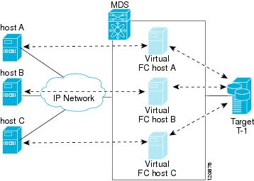
When an iSCSI host connects to the IPS module or MPS-14/2 module, a virtual host N port (HBA port) is created for the host (see Figure 43-10). Every Fibre Channel N port requires a unique Node WWN and Port WWN.
Figure 43-10 Virtual Host HBA Port
After the virtual N port is created with the WWNs, a fabric login (FLOGI) is done through the virtual iSCSI interface of the IPS port. After the FLOGI is completed, the virtual N port is online in the Fibre Channel SAN and virtual N port is registered in the Fibre Channel name server. The IPS module or MPS-14/2 module registers the following entries in the Fibre Channel name server:
•
•
•
•
•
When all the iSCSI sessions from the iSCSI host are terminated, the IPS modules or MPS-14/2 modules perform an explicit Fabric logout (FLOGO) to remove the virtual N-port device from the Fibre Channel SAN (this indirectly de-registers the device from the Fibre Channel name server).
For every iSCSI session from the host to the iSCSI virtual target there is a corresponding Fibre Channel session to the real Fibre Channel target. In Figure 43-10, there are three iSCSI hosts and all three of them connect to the same Fibre Channel target. There is one Fibre Channel session from each of the three virtual Fibre Channel hosts to the target.
iSCSI Initiator Idle Timeout
iSCSI initiator idle timeout specifies the time for which the virtual Fibre Channel N port is kept idle after the initiator logs out from its last iSCSI session. The default value for this timer is 300 seconds. This is useful to avoid N ports logging in to and logging off of the Fibre Channel SAN as transient failure occurs in the IP network. This helps reduce unnecessary RSCNs being generated in the Fibre Channel SAN.
To configure the initiator idle timeout, follow these steps:
WWN Assignment for iSCSI Initiators
An iSCSI host is mapped to an N port's WWNs by one of the following mechanisms:
•
•
Dynamic Mapping
With dynamic mapping, an iSCSI host is mapped to a dynamically generated port WWN (pWWN) and node WWN (nWWN). Each time the iSCSI host connects it might be mapped to a different WWN. Use this option if no access control is required on the Fibre Channel target device (because the target device access control is usually configured using the host WWN).
The WWNs are allocated from the MDS switch's WWN pool. The WWN mapping to the iSCSI host is maintained as long as the iSCSI host has at least one iSCSI session to the IPS port. When all iSCSI sessions from the host are terminated and the IPS module or MPS-14/2 module performs an FLOGO for the virtual N port of the host, the WWNs are released back to the switch's Fibre Channel WWN pool. These addresses are then available for assignment to other iSCSI hosts requiring access to the Fibre Channel Fabric.
The following are three dynamic initiator modes are supported:
•
•
•
iSCSI dynamic mapping is the default mode of operation. This configuration is distributed using CFS.
Note
To configure dynamic mapping (using the name option) for an iSCSI initiator, follow these steps:
Static Mapping
With static mapping, an iSCSI host is mapped to a specific pWWN and nWWN. This mapping is maintained in persistent storage and each time the iSCSI host connects, the same WWN mapping is used. This mode is required if you use access control on the target device.
You can implement static mapping in one of two ways:
•
•
Tip
To configure static mapping (using the name option) for an iSCSI initiator, follow these steps:
To configure static mapping (using the ip-address option) for an iSCSI initiator, follow these steps:
To assign the WWN for an iSCSI initiator, follow these steps:
Note
Making the Dynamic iSCSI Initiator WWN Mapping Static
After a dynamic iSCSI initiator has already logged in, you may decide to permanently keep the automatically assigned nWWN/pWWN mapping so this initiator uses the same mapping the next time it logs in.
You can convert a dynamic iSCSI initiator to static iSCSI initiator and make its WWNs persistent (see "Dynamic Mapping" section).
Note
To permanently keep the automatically assigned nWWN/pWWN mapping, follow these steps:
Checking for WWN Conflicts
WWNs assigned to static iSCSI initiators by the system can be inadvertently returned to the system when an upgrade fails or you downgrade the system software (manually booting up an older Cisco MDS SAN-OS release without using the install all command). In these instances, the system can later assign those WWNs to other iSCSI initiators (dynamic or static) and cause conflicts.
You can address this problem by checking for and removing any configured WWNs that belong to the system whenever such scenarios occur.
To check for and remove WWN conflicts, follow these steps:
Proxy- Initiator Mode
In the event that the Fibre Channel storage device requires explicit LUN access control for every host, use the transparent initiator mode (presenting one iSCSI host as one Fibre Channel host). Every iSCSI host has to be configured statically. This can mean several configuration tasks for each iSCSI host. If you do not need explicit LUN access control, using the proxy initiator mode simplifies the configuration.
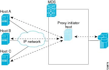
In this mode, only one virtual host N port (HBA port) is created per IPS port. All the iSCSI hosts connecting to that IPS port will be multiplexed using the same virtual host N port (see Figure 43-11). This mode simplifies the task of statically binding WWNs. LUN mapping and assignment on the Fibre Channel storage array must be configured to allow access from the proxy virtual N port's pWWN for all LUNs used by each iSCSI initiator that connects through this IPS port. The LUN is then assigned to each iSCSI initiator by configuring iSCSI virtual targets (see the "Static Mapping" section) with LUN mapping and iSCSI access control (see the "iSCSI Access Control" section).
Figure 43-11 Multiplexing IPS Ports
Proxy initiator mode can be configured on a per IPS port basis, in which case only iSCSI initiators terminating on that IPS port will be in this mode.
When an IPS port is configured in proxy-initiator mode, fabric login (FLOGI) is done through the virtual iSCSI interface of the IPS port. After the FLOGI is completed, the proxy-initiator virtual N port is online in the Fibre Channel fabric and virtual N port is registered in the Fibre Channel name server. The IPS module or MPS-14/2 module registers the following entries in the Fibre Channel name server:
•
•
•
•
Similar to transparent initiator mode, the user can provide a pWWN and nWWN or request a system assigned WWN for the proxy initiator N port.
Caution
To configure the proxy initiator, follow these steps:
Note
VSAN Membership for iSCSI
Similar to Fibre Channel devices, iSCSI devices have two mechanisms by which VSAN membership can be defined.
•
•
VSAN Membership for iSCSI Hosts
Individual iSCSI hosts can be configured to be in a specific VSAN (similar to the DPVM feature for Fibre Channel, see Chapter 22, "Creating Dynamic VSANs"). The specified VSAN overrides the iSCSI interface VSAN membership.
To assign VSAN membership for iSCSI hosts, follow these steps:
Note
VSAN Membership for iSCSI Interfaces
VSAN membership can be configured for an iSCSI interface, called the port VSAN. All the iSCSI devices that connect to this interface automatically become members of this VSAN, if it is not explicitly configured in a VSAN. In other words, the port VSAN of an iSCSI interface is the default VSAN for all dynamic iSCSI initiators. The default port VSAN of an iSCSI interface is VSAN 1.
Caution
To change the default port VSAN for an iSCSI interface, follow these steps:
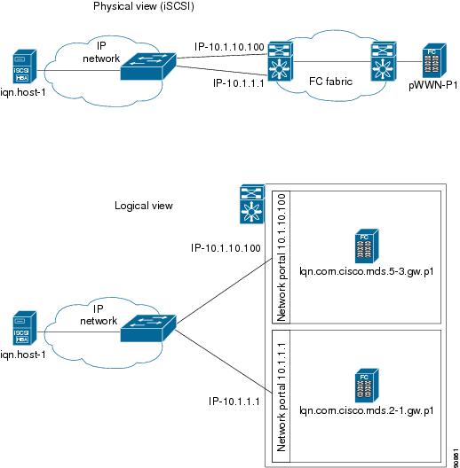
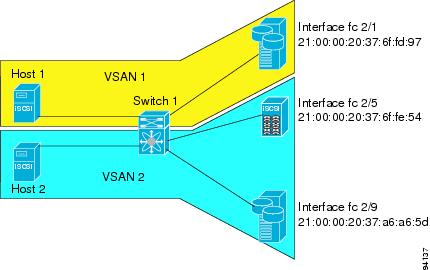
Example of VSAN Membership for iSCSI Devices
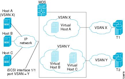
Figure 43-12 provides an example of VSAN membership for iSCSI devices:
•
•
•
Figure 43-12 VSAN Membership for iSCSI Interfaces
Host A's virtual Fibre Channel N port will be added to VSAN X because of explicit membership for the initiator. The virtual host-B and host-C N ports do not have any explicit membership configuration so they will inherit the iSCSI interface VSAN membership and be part of VSAN Y.
Advanced VSAN Membership for iSCSI Hosts
An iSCSI host can be a member of multiple VSANs. In this case multiple virtual Fibre Channel hosts are created, one in each VSAN in which the iSCSI host is a member. This configuration is useful when certain resources such as Fibre Channel tape devices need to be shared among different VSANs.
iSCSI Access Control
Two mechanisms of access control are available for iSCSI devices.
•
•
Depending on the initiator mode used to present the iSCSI hosts in the Fibre Channel fabric, either or both the access control mechanisms can be used.
The topics included in this section are:
•
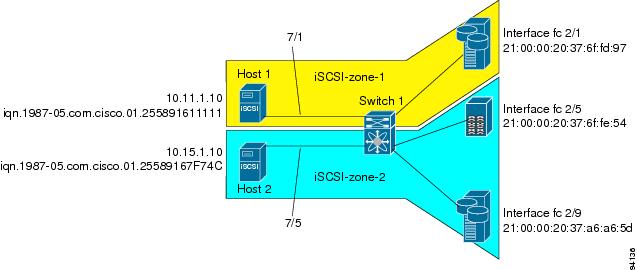
Fibre Channel Zoning-Based Access Control
Cisco SAN-OS VSAN and zoning concepts have been extended to cover both Fibre Channel devices and iSCSI devices. Zoning is the standard access control mechanism for Fibre Channel devices, which is applied within the context of a VSAN. Fibre Channel zoning has been extended to support iSCSI devices, and this extension has the advantage of having a uniform, flexible access control mechanism across the whole SAN.
Common mechanisms for identifying members in a Fibre Channel zone are the following (see Chapter 24, "Configuring and Managing Zones" for details on Fibre Channel zoning):
•
•
In the case of iSCSI, behind an iSCSI interface multiple iSCSI devices may be connected. Interface-based zoning may not be useful because all the iSCSI devices behind the interface will automatically be within the same zone.
In transparent initiator mode (where one Fibre Channel virtual N port is created for each iSCSI host as described in the "Transparent Initiator Mode" section), if an iSCSI host has static WWN mapping then the standard Fibre Channel device pWWN-based zoning membership mechanism can be used.
Zoning membership mechanism has been enhanced to add iSCSI devices to zones based on the following:
•
•
•
•
For iSCSI hosts that do not have a static WWN mapping, the feature allows the IP address or iSCSI node name to be specified as zone members. Note that iSCSI hosts that have static WWN mapping can also use these features. IP address based zone membership allows multiple devices to be specified in one command by providing the subnet mask.
Note
To add an iSCSI initiator to the zone database, follow these steps:
iSCSI-Based Access Control
iSCSI-based access control is applicable only if static iSCSI virtual targets are created (see the "Static Mapping" section). For a static iSCSI target, you can configure a list of iSCSI initiators that are allowed to access the targets.
By default, static iSCSI virtual targets are not accessible to any iSCSI host. You must explicitly configure accessibility to allow an iSCSI virtual target to be accessed by all hosts. The initiator access list can contain one or more initiators. The iSCSI initiator can be identified by one of the following mechanisms:
•
•
•
Note
To configure access control in iSCSI, follow these steps:
Enforcing Access Control
IPS modules and MPS-14/2 modules use both iSCSI and Fibre Channel zoning-based access control lists to enforce access control. Access control is enforced both during the iSCSI discovery phase and the iSCSI session creation phase. Access control enforcement is not required during the I/O phase because the IPS module or MPS-14/2 module is responsible for the routing of iSCSI traffic to Fibre Channel.
•
•
If the iSCSI target is a static mapped target, the IPS module or MPS-14/2 module verifies if the iSCSI host is allowed within the access list of the iSCSI target. If the IP host does not have access, its login is rejected. If the iSCSI host is allowed, it validates if the virtual Fibre Channel N port used by the iSCSI host and the Fibre Channel target mapped to the static iSCSI virtual target are in the same Fibre Channel zone.
If the iSCSI target is an autogenerated iSCSI target, then the IPS module or MPS-14/2 module extracts the WWN of the Fibre Channel target from the iSCSI target name and verifies if the initiator and the Fibre Channel target is in the same Fibre Channel zone or not. If they are, then access is allowed.
The IPS module or MPS-14/2 module uses the Fibre Channel virtual N port of the iSCSI host and does a zone-enforced name server query for the Fibre Channel target WWN. If the FC ID is returned by the name server, then the iSCSI session is accepted. Otherwise, the login request is rejected.
iSCSI Session Authentication
The IPS module or MPS-14/2 module supports the iSCSI authentication mechanism to authenticate the iSCSI hosts that request access to the storage devices. By default, the IPS modules or MPS-14/2 modules allow CHAP or None authentication of iSCSI initiators. If authentication is always used, you must configure the switch to allow only CHAP authentication.
For CHAP user name or secret validation, you can use any method supported and allowed by the Cisco MDS AAA infrastructure (see Chapter 34, "Configuring RADIUS and TACACS+"). AAA authentication supports a RADIUS, TACACS+, or local authentication device.
The aaa authentication iscsi command enables AAA authentication for the iSCSI host and specifies the method to use.
To configure AAA authentication for an iSCSI user, follow these steps:
The sections included in this topic are:
•
Authentication Mechanism
You can configure iSCSI CHAP or None authentication at both the global level and at each interface level.
The authentication for a Gigabit Ethernet interface or subinterface overrides the authentication method configured at the global level.
If CHAP authentication is used, issue the iscsi authentication chap command at either the global level or at a per-interface level. If authentication should not be used at all, issue the iscsi authentication none command.
To configure the authentication mechanism for iSCSI, follow these steps:
To configure the authentication mechanism for iSCSI sessions to a particular interface, follow these steps:
Local Authentication
See the"Characteristics of Strong Passwords" section on page 32-11 to create the local password database. To create users in the local password database for the iSCSI initiator, the iSCSI keyword is mandatory.
To configure iSCSI users for local authentication, follow these steps:
Restricting iSCSI Initiator Authentication
By default, the iSCSI initiator can use any user name in the RADIUS server or in the local database in authenticating itself to the IPS module or MPS-14/2 module (the CHAP user name is independent of the iSCSI initiator name). The IPS module or MPS-14/2 module allows the initiator to log in as long as it provides a correct response to the CHAP challenge sent by the switch. This can be a problem if one CHAP user name and password has been compromised.
To restrict an initiator to use a specific user name for CHAP authentication, follow these steps:
Mutual CHAP Authentication
In addition to the IPS module or MPS-14/2 module authentication of the iSCSI initiator, the IPS module or MPS-14/2 module also supports a mechanism for the iSCSI initiator to authenticate the Cisco MDS switch's iSCSI target during the iSCSI login phase. This authentication requires the user to configure a user name and password for the switch to present to the iSCSI initiator. The provided password is used to calculate a CHAP response to a CHAP challenge sent to the IPS port by the initiator.
To configure a global iSCSI target user name and password to be used by the switch to authenticate itself to an initiator, follow these steps:
To configure a per-initiator iSCSI target's user name and password used by the switch to authenticate itself to an initiator, follow these steps:
Use the show running-config and the show iscsi global commands to display the global configuration. Use the show running-config and the show iscsi initiator configured commands to display the initiator specific configuration.(See the "Displaying iSCSI Information" section for command output examples.)
iSCSI Immediate Data and Unsolicited Data Features
Cisco MDS switches support the iSCSI immediate data and unsolicited data features if requested by the initiator during the login negotiation phase. Immediate data is iSCSI write data contained in the data segment of an iSCSI command protocol data unit (PDU), such as combining the write command and write data together in one PDU. Unsolicited data is iSCSI write data that an initiator sends to the iSCSI target, such as an MDS switch, in an iSCSI data-out PDU without having to receive an explicit ready to transfer (R2T) PDU from the target.
These two features help reduce I/O time for small write commands because it removes one round-trip between the initiator and the target for the R2T PDU. As an iSCSI target, the MDS switch allows up to 64 KB of unsolicited data per command. This is controlled by the FirstBurstLength parameter during iSCSI login negotiation phase.
If an iSCSI initiator supports immediate data and unsolicited data features, these features are automatically enabled on the MDS switch with no configuration required.
iSCSI Interface Advanced Features
Advanced configuration options are available for iSCSI interfaces on a per-IPS port basis. These configurations are similar to the advanced FCIP configurations and are already explained in that section (see the "Advanced FCIP Profile Configuration" section on page 41-12).
To access these commands from the iSCSI interface, follow these steps:
Step 1
Enters configuration mode.
Step 2
Selects the iSCSI interface on the switch.
Cisco MDS switches support the following advanced features for iSCSI interfaces:
•
iSCSI Listener Port
You can configure the TCP port number for the iSCSI interface that listens for new TCP connections. The default port number is 3260. Once you change the TCP port number, the iSCSI port only accepts TCP connections on the newly configured port.
TCP Tuning Parameters
You can configure the following TCP parameters:
•
•
•
•
•
•
•
•
•
QoS
To set the QoS values, follow these steps:
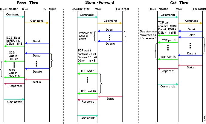
iSCSI Routing Modes
Cisco MDS 9000 Family switches support multiple iSCSI routing modes. Each mode negotiates different operational parameters, has different advantages and disadvantages, and is suitable for different usages.
•
In pass-thru mode, the port on the IPS module or MPS 14/2 module converts and forwards read data frames from the Fibre Channel target to the iSCSI host frame-by-frame without buffering. This means that one data-in frame received is immediately sent out as one iSCSI data-in PDU.
In the opposite direction, the port on the IPS module or MPS 14/2 module limits the maximum size of iSCSI write data-out PDU that the iSCSI host can send to the maximum data size that the Fibre Channel target specifies that it can receive. The result is one iSCSI data-out PDU received sent out as one Fibre Channel data frame to the Fibre Channel target.
The absence of buffering in both directions leads to an advantage of lower forwarding latency. However, a small maximum data segment length usually results in lower data transfer performance from the host because of a higher processing overhead by the host system. Another benefit of this mode is iSCSI data digest can be enabled. This helps protect the integrity of iSCSI data carried in the PDU over what TCP checksum offers.
•
In store-and-forward mode, the port on the IPS module or MPS 14/2 module assembles all the Fibre Channel data frames of an exchange to build one large iSCSI data-in PDU before forwarding it to the iSCSI client.
In the opposite direction, the port on the IPS module or MPS 14/2 module does not impose a small data segment size on the host so the iSCSI host can send an iSCSI data-out PDU of any size (up to 256 KB). The port then waits until the whole iSCSI data-out PDU is received before it converts, or splits, the PDU, and forwards Fibre Channel frames to the Fibre Channel target.
The advantage of this mode is higher data transfer performance from the host. The disadvantages are higher transfer latency and that the iSCSI data digest (CRC) cannot be used.
Note
•
Cut-through mode improves the read operation performance over store-and-forward mode. The port on the IPS module or MPS 14/2 module achieves this by forwarding each Fibre Channel data-in frame to the iSCSI host as it is received without waiting for the whole exchange complete. There is no difference for write data-out operations from store-and-forward mode.
Figure 43-13 compares the messages exchanged by the iSCSI routing modes.
Figure 43-13 iSCSI Routing Modes
Table 43-1 compares the advantages and disadvantages of the different iSCSI routing modes.
Caution
To set the iSCSI routing mode, follow this step:
Displaying iSCSI Information
Use the show iscsi command to obtain detailed information about iSCSI configurations.
This section includes the following topics:
•
•
•
•
Displaying iSCSI Interfaces
Use the show iscsi interface command to view the summary, counter, description, and status of the iSCSI interface. Use the output to verify the administrative mode, the interface status, TCP parameters currently used, and brief statistics.
Example 43-1 Displays the iSCSI Interface Information
switch# show interface iscsi 4/1iscsi4/1 is upHardware is GigabitEthernetPort WWN is 20:cf:00:0c:85:90:3e:80Admin port mode is ISCSIPort mode is ISCSISpeed is 1 GbpsiSCSI initiator is identified by nameNumber of iSCSI session: 0 (discovery session: 0)Number of TCP connection: 0Configured TCP parametersLocal Port is 3260PMTU discover is enabled, reset timeout is 3600 secKeepalive-timeout is 60 secMinimum-retransmit-time is 300 msMax-retransmissions 4Sack is enabledQOS code point is 0Maximum allowed bandwidth is 1000000 kbpsMinimum available bandwidth is 70000 kbpsEstimated round trip time is 1000 usecSend buffer size is 4096 KBCongestion window monitoring is enabled, burst size is 50 KBConfigured maximum jitter is 500 usForwarding mode: store-and-forwardTMF Queueing Mode : disabledProxy Initiator Mode : disabled5 minutes input rate 0 bits/sec, 0 bytes/sec, 0 frames/sec5 minutes output rate 0 bits/sec, 0 bytes/sec, 0 frames/seciSCSI statisticsInput 0 packets, 0 bytesCommand 0 pdus, Data-out 0 pdus, 0 bytesOutput 0 packets, 0 bytesResponse 0 pdus (with sense 0), R2T 0 pdusData-in 0 pdus, 0 bytesDisplaying iSCSI Statistics
Use the show iscsi stats command to view brief or detailed iSCSI statistics per iSCSI interface. See Example 43-2 and Example 43-3.
Example 43-2 displays iSCSI throughput on an IPS port in both inbound and outbound directions. It also displays the number of different types of iSCSI PDU received and transmitted by this IPS port.
Example 43-2 Display Brief iSCSI Statistics for an iSCSI Interface
switch# show iscsi stats iscsi 2/1iscsi2/15 minutes input rate 704 bits/sec, 88 bytes/sec, 1 frames/sec5 minutes output rate 704 bits/sec, 88 bytes/sec, 1 frames/seciSCSI statistics974756 packets input, 142671620 bytesCommand 2352 pdus, Data-out 44198 pdus, 92364800 bytes, 0 fragments, unsolicited 0 bytesoutput 1022920 packets, 143446248 bytesResponse 2352 pdus (with sense 266), R2T 1804 pdusData-in 90453 pdus, 92458248 bytesExample 43-3 displays detailed iSCSI statistics for an IPS port. Along with the traffic rate and the number of each iSCSI PDU type, it shows the number of FCP frames received and forwarded, the number of iSCSI login attempts, successes, and failures. It also shows the number of different types of iSCSI PDUs sent and received that are noncritical or occur less frequently, such as NOP in and out (NOP-In and NOP-Out), text request and response (Text-REQ and Text-RESP), and task management request and response (TMF-REQ and TMF-RESP).
Various types of errors and PDU or frame drop occurrences are also counted and displayed. For example, Bad header digest shows the number of iSCSI PDUs received that have a header digest that fails CRC verification. The iSCSI Drop section shows the number of PDUs that were dropped because of reasons such as target down, LUN mapping fail, Data CRC error, or unexpected Immediate or Unsolicited data. These statistics are helpful for debugging purposes when the feature is not working as expected.
The last section, Buffer Stats, gives statistics on the internal IPS packet buffer operation. This section is for debugging purposes only.
Example 43-3 Displays Detailed iSCSI Statistics for the iSCSI Interface
switch# show iscsi stats iscsi 2/1 detailiscsi2/15 minutes input rate 704 bits/sec, 88 bytes/sec, 1 frames/sec5 minutes output rate 704 bits/sec, 88 bytes/sec, 1 frames/seciSCSI statistics974454 packets input, 142656516 bytesCommand 2352 pdus, Data-out 44198 pdus, 92364800 bytes, 0 fragments, unsolicited 0 bytesoutput 1022618 packets, 143431144 bytesResponse 2352 pdus (with sense 266), R2T 1804 pdusData-in 90453 pdus, 92458248 bytesiSCSI Forward:Command:2352 PDUs (Rcvd:2352)Data-Out (Write):16236 PDUs (Rcvd 44198), 0 fragments, 92364800 bytes, unsolicited 0 bytesFCP Forward:Xfer_rdy:1804 (Rcvd:1804)Data-In:90453 (Rcvd:90463), 92458248 bytesResponse:2352 (Rcvd:2362), with sense 266TMF Resp:0iSCSI Stats:Login:attempt:13039, succeed:110, fail:12918, authen fail:0Rcvd:NOP-Out:914582, Sent:NOP-In:914582NOP-In:0, Sent:NOP-Out:0TMF-REQ:0, Sent:TMF-RESP:0Text-REQ:18, Sent:Text-RESP:27SNACK:0Unrecognized Opcode:0, Bad header digest:0Command in window but not next:0, exceed wait queue limit:0Received PDU in wrong phase:0SCSI Busy responses:0Immediate data failure::Separation:0Unsolicited data failure::Separation:0, Segment:0Add header:0Sequence ID allocation failure:0FCP Stats:Total:Sent:47654Received:96625 (Error:0, Unknown:0)Sent:PLOGI:10, Rcvd:PLOGI_ACC:10, PLOGI_RJT:0PRLI:10, Rcvd:PRLI_ACC:10, PRLI_RJT:0, Error:0, From initiator:0LOGO:4, Rcvd:LOGO_ACC:0, LOGO_RJT:0PRLO:4, Rcvd:PRLO_ACC:0, PRLO_RJT:0ABTS:0, Rcvd:ABTS_ACC:0TMF REQ:0Self orig command:10, Rcvd:data:10, resp:10Rcvd:PLOGI:156, Sent:PLOGI_ACC:0, PLOGI_RJT:156LOGO:0, Sent:LOGO_ACC:0, LOGO_RJT:0PRLI:8, Sent:PRLI_ACC:8, PRLI_RJT:0PRLO:0, Sent:PRLO_ACC:0, PRLO_RJT:0ADISC:0, Sent:ADISC_ACC:0, ADISC_RJT:0ABTS:0iSCSI Drop:Command:Target down 0, Task in progress 0, LUN map fail 0CmdSeqNo not in window 0, No Exchange ID 0, Reject 0No task:0Data-Out:0, Data CRC Error:0TMF-Req:0, No task:0Unsolicited data:0, Immediate command PDU:0FCP Drop:Xfer_rdy:0, Data-In:0, Response:0Buffer Stats:Buffer less than header size:0, Partial:45231, Split:322Pullup give new buf:0, Out of contiguous buf:0, Unaligned m_data:0Displaying Proxy Initiator Information
If the proxy initiator feature is enabled in the iSCSI interface, use the show interface iscsi command to display configured proxy initiator information (see Example 43-4 and Example 43-5).
Example 43-4 Displays Proxy Initiator Information for the iSCSI Interface with System-Assigned WWNs
switch# show interface iscsi 4/1iscsi4/1 is upHardware is GigabitEthernetPort WWN is 20:c1:00:05:30:00:a7:9eAdmin port mode is ISCSIPort mode is ISCSISpeed is 1 GbpsiSCSI initiator is identified by nameNumber of iSCSI session: 0, Number of TCP connection: 0Configured TCP parametersLocal Port is 3260PMTU discover is enabled, reset timeout is 3600 secKeepalive-timeout is 60 secMinimum-retransmit-time is 300 msMax-retransmissions 4Sack is disabledQOS code point is 0Forwarding mode: pass-thruTMF Queueing Mode : disabledProxy Initiator Mode : enabled<----------------------------Proxy initiator is enablednWWN is 28:00:00:05:30:00:a7:a1 (system-assigned)<----System-assigned nWWNpWWN is 28:01:00:05:30:00:a7:a1 (system-assigned)<---- System-assigned pWWN5 minutes input rate 0 bits/sec, 0 bytes/sec, 0 frames/sec5 minutes output rate 0 bits/sec, 0 bytes/sec, 0 frames/seciSCSI statisticsInput 7 packets, 2912 bytesCommand 0 pdus, Data-out 0 pdus, 0 bytesOutput 7 packets, 336 bytesResponse 0 pdus (with sense 0), R2T 0 pdusData-in 0 pdus, 0 bytesExample 43-5 Displays Proxy Initiator Information for the iSCSI Interface with User-Assigned WWNs
switch# show interface iscsi 4/2iscsi4/2 is upHardware is GigabitEthernetPort WWN is 20:c1:00:05:30:00:a7:9eAdmin port mode is ISCSIPort mode is ISCSISpeed is 1 GbpsiSCSI initiator is identified by nameNumber of iSCSI session: 0, Number of TCP connection: 0Configured TCP parametersLocal Port is 3260PMTU discover is enabled, reset timeout is 3600 secKeepalive-timeout is 60 secMinimum-retransmit-time is 300 msMax-retransmissions 4Sack is disabledQOS code point is 0Forwarding mode: pass-thruTMF Queueing Mode : disabledProxy Initiator Mode : enablednWWN is 11:11:11:11:11:11:11:11 (manually-configured)<----User-assigned nWWNpWWN is 22:22:22:22:22:22:22:22 (manually-configured)<----User-assigned pWWN5 minutes input rate 0 bits/sec, 0 bytes/sec, 0 frames/sec5 minutes output rate 0 bits/sec, 0 bytes/sec, 0 frames/seciSCSI statisticsInput 7 packets, 2912 bytesCommand 0 pdus, Data-out 0 pdus, 0 bytesOutput 7 packets, 336 bytesResponse 0 pdus (with sense 0), R2T 0 pdusData-in 0 pdus, 0 bytesDisplaying Global iSCSI Information
Use the show iscsi global command to view the overall configuration and the iSCSI status. See Example 43-6.
Example 43-6 Displays the Current Global iSCSI Configuration and State
switch# show iscsi globaliSCSI Global informationAuthentication: CHAP, NONEImport FC Target: EnabledInitiator idle timeout: 300 secondsNumber of target node: 0Number of portals: 11Number of session: 0Failed session: 0, Last failed initiator name:Displaying iSCSI Sessions
Use the show iscsi session command to view details about the current iSCSI sessions in the switch. Without parameters, this command displays all sessions. The output can be filtered by specifying an initiator, a target, or both.
Example 43-7 displays one iSCSI initiator configured based on the IQN (iqn.1987-05.com.cisco:02.3021b0f2fda0.avanti12-w2k) and another based on its IPv4 address (10.10.100.199).
Example 43-7 Displays Brief Information of All iSCSI Sessions
switch# show iscsi sessionInitiator iqn.1987-05.com.cisco:02.3021b0f2fda0.avanti12-w2kInitiator ip addr (s): 10.10.100.116Session #1Discovery session, ISID 00023d000043, Status activeSession #2Target VT1VSAN 1, ISID 00023d000046, Status active, no reservationSession #3Target VT2VSAN 1, ISID 00023d000048, Status active, no reservationInitiator 10.10.100.199Initiator name iqn.1987-05.com.cisco.01.7e3183ae458a94b1cd6bc168cba09d2eSession #1Target VT2VSAN 1, ISID 246700000000, Status active, no reservationSession #2Target VT1VSAN 1, ISID 246b00000000, Status active, no reservationSession #3Target iqn.1987-05.com.cisco:05.switch.04-01.2100002037a6be32VSAN 1, ISID 246e00000000, Status active, no reservationExample 43-8 and Example 43-9 display the iSCSI initiator configured based on its IPv4 address (10.10.100.199).
Example 43-8 Displays Brief Information About the Specified iSCSI Session
switch# show iscsi session initiator 10.10.100.199 target VT1Initiator 10.10.100.199Initiator name iqn.1987-05.com.cisco.01.7e3183ae458a94b1cd6bc168cba09d2eSession #1Target VT1VSAN 1, ISID 246b00000000, Status active, no reservationExample 43-9 Displays Detailed Information About the Specified iSCSI Session
switch# show iscsi session initiator 10.10.100.199 target VT1 detailInitiator 10.10.100.199 (oasis-qa)Initiator name iqn.1987-05.com.cisco.01.7e3183ae458a94b1cd6bc168cba09d2eSession #1 (index 3)Target VT1VSAN 1, ISID 246b00000000, TSIH 384, Status active, no reservationType Normal, ExpCmdSN 39, MaxCmdSN 54, Barrier 0MaxBurstSize 0, MaxConn 0, DataPDUInOrder NoDataSeqInOrder No, InitialR2T Yes, ImmediateData NoRegistered LUN 0, Mapped LUN 0Stats:PDU: Command: 38, Response: 38Bytes: TX: 8712, RX: 0Number of connection: 1Connection #1Local IP address: 10.10.100.200, Peer IP address: 10.10.100.199CID 0, State: LOGGED_INStatSN 62, ExpStatSN 0MaxRecvDSLength 1024, our_MaxRecvDSLength 1392CSG 3, NSG 3, min_pdu_size 48 (w/ data 48)AuthMethod none, HeaderDigest None (len 0), DataDigest None (len 0)Version Min: 2, Max: 2FC target: Up, Reorder PDU: No, Marker send: No (int 0)Received MaxRecvDSLen key: NoDisplaying iSCSI Initiators
Use the show iscsi initiator command to display information about all initiators connected to an iSCSI interface in the switch. The information can be filtered to display only the desired iSCSI initiator by specifying the initiator name. Detailed output of the iSCSI initiator can be obtained by specifying the detail option. The iscsi-session (and optionally detail) parameter displays only iSCSI session information. The fcp-session (and optionally detail) parameter displays only FCP session information. The output includes static and dynamic initiators. See Example 43-10 and Example 43-11.
Example 43-10 Displays Information About Connected iSCSI Initiators
switch# show iscsi initiatoriSCSI Node name is iqn.1987-05.com.cisco:02.3021b0f2fda0.avanti12-w2kInitiator ip addr (s): 10.10.100.116iSCSI alias name: AVANTI12-W2KNode WWN is 22:01:00:05:30:00:10:e1 (configured)Member of vsans: 1, 2, 10Number of Virtual n_ports: 1Virtual Port WWN is 22:04:00:05:30:00:10:e1 (configured)Interface iSCSI 4/1, Portal group tag: 0x180VSAN ID 1, FCID 0x6c0202VSAN ID 2, FCID 0x6e0000VSAN ID 10, FCID 0x790000iSCSI Node name is 10.10.100.199iSCSI Initiator name: iqn.1987-05.com.cisco.01.7e3183ae458a94b1cd6bc168cba09d2eiSCSI alias name: oasis-qaNode WWN is 22:03:00:05:30:00:10:e1 (configured)Member of vsans: 1, 5Number of Virtual n_ports: 1Virtual Port WWN is 22:00:00:05:30:00:10:e1 (configured)Interface iSCSI 4/1, Portal group tag: 0x180VSAN ID 5, FCID 0x640000VSAN ID 1, FCID 0x6c0203Example 43-11 Displays Detailed Information About the iSCSI Initiator
switch# show iscsi initiator iqn.1987-05.com.cisco:02.3021b0f2fda0.avanti12-w2k detailiSCSI Node name is iqn.1987-05.com.cisco:02.3021b0f2fda0.avanti12-w2kInitiator ip addr (s): 10.10.100.116iSCSI alias name: AVANTI12-W2KNode WWN is 22:01:00:05:30:00:10:e1 (configured)Member of vsans: 1, 2, 10Number of Virtual n_ports: 1Virtual Port WWN is 22:04:00:05:30:00:10:e1 (configured)Interface iSCSI 4/1, Portal group tag is 0x180VSAN ID 1, FCID 0x6c02021 FC sessions, 1 iSCSI sessionsiSCSI session details <-------------------iSCSI session detailsTarget: VT1Statistics:PDU: Command: 0, Response: 0Bytes: TX: 0, RX: 0Number of connection: 1TCP parametersLocal 10.10.100.200:3260, Remote 10.10.100.116:4190Path MTU: 1500 bytesRetransmission timeout: 310 msRound trip time: Smoothed 160 ms, Variance: 38Advertized window: Current: 61 KB, Maximum: 62 KB, Scale: 0Peer receive window: Current: 63 KB, Maximum: 63 KB, Scale: 0Congestion window: Current: 1 KBFCP Session details <-------------------FCP session detailsTarget FCID: 0x6c01e8 (S_ID of this session: 0x6c0202)pWWN: 21:00:00:20:37:62:c0:0c, nWWN: 20:00:00:20:37:62:c0:0cSession state: CLEANUP1 iSCSI sessions share this FC sessionTarget: VT1Negotiated parametersRcvDataFieldSize 1392 our_RcvDataFieldSize 1392MaxBurstSize 0, EMPD: FALSERandom Relative Offset: FALSE, Sequence-in-order: YesStatistics:PDU: Command: 0, Response: 0Use the show fcns database (and optionally detail) to display the Fibre Channel name server entry for the Fibre Channel N port created for iSCSI initiators in the SAN. See Example 43-12 and Example 43-13.
Example 43-12 Displays the FCNS Database Contents
switch# show fcns databaseVSAN 1:--------------------------------------------------------------------------FCID TYPE PWWN (VENDOR) FC4-TYPE:FEATURE--------------------------------------------------------------------------0x020101 N 22:04:00:05:30:00:35:e1 (Cisco) scsi-fcp:init isc..w <--iSCSI0x020102 N 22:02:00:05:30:00:35:e1 (Cisco) scsi-fcp:init isc..w initiator0x0205d4 NL 21:00:00:04:cf:da:fe:c6 (Seagate) scsi-fcp:target0x0205d5 NL 21:00:00:04:cf:e6:e4:4b (Seagate) scsi-fcp:target...Total number of entries = 10VSAN 2:--------------------------------------------------------------------------FCID TYPE PWWN (VENDOR) FC4-TYPE:FEATURE--------------------------------------------------------------------------0xef0001 N 22:02:00:05:30:00:35:e1 (Cisco) scsi-fcp:init isc..wTotal number of entries = 1VSAN 3:--------------------------------------------------------------------------FCID TYPE PWWN (VENDOR) FC4-TYPE:FEATURE--------------------------------------------------------------------------0xed0001 N 22:02:00:05:30:00:35:e1 (Cisco) scsi-fcp:init isc..wTotal number of entries = 1Example 43-13 Displays the FCNS Database in Detail
switch# show fcns database detail------------------------VSAN:1 FCID:0x020101------------------------port-wwn (vendor) :22:04:00:05:30:00:35:e1 (Cisco)node-wwn :22:03:00:05:30:00:35:e1class :2,3node-ip-addr :10.2.2.12 <--- iSCSI initiator's IPv4 addressipa :ff ff ff ff ff ff ff fffc4-types:fc4_features:scsi-fcp:init iscsi-gwsymbolic-port-name :symbolic-node-name :iqn.1991-05.com.microsoft:oasis2-dell <--- iSCSI initiator's IQNport-type :Nport-ip-addr :0.0.0.0fabric-port-wwn :22:01:00:05:30:00:35:dehard-addr :0x000000------------------------VSAN:1 FCID:0x020102------------------------port-wwn (vendor) :22:02:00:05:30:00:35:e1 (Cisco)node-wwn :22:01:00:05:30:00:35:e1class :2,3node-ip-addr :10.2.2.11ipa :ff ff ff ff ff ff ff fffc4-types:fc4_features:scsi-fcp:init iscsi-gwsymbolic-port-name :symbolic-node-name :iqn.1987-05.com.cisco.01.14ac33ba567f986f174723b5f9f2377port-type :Nport-ip-addr :0.0.0.0fabric-port-wwn :22:01:00:05:30:00:35:dehard-addr :0x000000...Total number of entries = 10======================================================================------------------------VSAN:2 FCID:0xef0001------------------------port-wwn (vendor) :22:02:00:05:30:00:35:e1 (Cisco)node-wwn :22:01:00:05:30:00:35:e1class :2,3node-ip-addr :10.2.2.11ipa :ff ff ff ff ff ff ff fffc4-types:fc4_features:scsi-fcp:init iscsi-gwsymbolic-port-name :symbolic-node-name :iqn.1987-05.com.cisco.01.14ac33ba567f986f174723b5f9f2377port-type :Nport-ip-addr :0.0.0.0fabric-port-wwn :22:01:00:05:30:00:35:dehard-addr :0x000000Total number of entries = 1...Use the show iscsi initiator configured to display information about all the configured iSCSI initiators. Specifying the name shows information about the desired initiator. See Example 43-14.
Example 43-14 Displays Information About Configured Initiators
switch# show iscsi initiator configurediSCSI Node name is iqn.1987-05.com.cisco:02.3021b0f2fda0.avanti12-w2kMember of vsans: 1, 2, 10Node WWN is 22:01:00:05:30:00:10:e1No. of PWWN: 5Port WWN is 22:04:00:05:30:00:10:e1Port WWN is 22:05:00:05:30:00:10:e1Port WWN is 22:06:00:05:30:00:10:e1Port WWN is 22:07:00:05:30:00:10:e1Port WWN is 22:08:00:05:30:00:10:e1iSCSI Node name is 10.10.100.199Member of vsans: 1, 5Node WWN is 22:03:00:05:30:00:10:e1No. of PWWN: 4Port WWN is 22:00:00:05:30:00:10:e1Port WWN is 22:09:00:05:30:00:10:e1Port WWN is 22:0a:00:05:30:00:10:e1Port WWN is 22:0b:00:05:30:00:10:e1User Name for Mutual CHAP: testuserDisplaying iSCSI Virtual Targets
Use the show iscsi virtual-target to display information about the Fibre Channel targets exported as iSCSI virtual targets to the iSCSI initiators. The output includes static as well as dynamic targets. See Example 43-15.
Example 43-15 Displays Exported Targets
switch# show iscsi virtual-targettarget: VT1* Port WWN 21:00:00:20:37:62:c0:0cConfigured nodeall initiator permit is enabledtarget: VT2Port WWN 21:00:00:04:cf:4c:52:c1Configured nodeall initiator permit is disabledtarget: iqn.1987-05.com.cisco:05.switch.04-01.2100002037a6be32Port WWN 21:00:00:20:37:a6:be:32 , VSAN 1Auto-created nodeDisplaying iSCSI User Information
The show user-account iscsi command displays all configured iSCSI user names. See Example 43-16.
Example 43-16 Displays iSCSI User Names
switch# show user-account iscsiusername:iscsiusersecret: dsfffsffsffasffsdffgusername:user2secret:cshadhdhsadadjajdjasConfiguring iSLB
The iSCSI server load balancing (iSLB) feature provides a means to easily configure large scale iSCSI deployments containing hundreds or even thousands of initiators. When not using iSLB, configuring iSCSI requires the following:
•
–
–
–
–
•
•
–
–
iSLB provides the following features:
•
•
Note
•
This section covers the following topics:
•
•
•
•
•
•
Note
Note
About iSLB Configuration Limits
iSLB configuration has the following limits:
•
•
•
•
•
•
•
•
•
•
iSLB Configuration Prerequisites
Perform the following prerequisite actions prior to configuring iSLB:
•
•
•
•
•
About iSLB Initiators
iSLB initiators provide the following features in addition to those supported by iSCSI initiators:
•
•
•
•
Configuring iSLB Initiators
This section includes the following topics:
•
•
•
•
•
•
•
•
•
•
Configuring iSLB Initiator Names or IP Addresses
You must specify the iSLB initiator name or IP address before configuring it.
Note
To enter iSLB initiator configuration submode using the name option for an iSLB initiator, follow these steps:
To enter iSLB initiator configuration submode using the ip-address option for an iSLB initiator, follow these steps:
Assigning WWNs to iSLB Initiators
An iSLB host is mapped to an N port's WWNs by one of the following mechanisms:
•
•
Note
Tip
Making the Dynamic iSLB Initiator WWN Mapping Static
After a dynamic iSLB initiator has logged in, you may decide to permanently keep the automatically assigned nWWN/pWWN mapping to allow this initiator to use the same mapping the next time it logs in .
You can convert a dynamic iSLB initiator to a static iSLB initiator and make its WWNs persistent (see "Dynamic Mapping" section).
Note
Note
Note
To permanently keep the automatically assigned nWWN/pWWN mapping, follow these steps:
Assigning VSAN Membership for iSLB Initiators
Individual iSLB hosts can be configured to be in a specific VSAN (similar to the DPVM feature for Fibre Channel; see Chapter 22, "Creating Dynamic VSANs"). The specified VSAN overrides the iSCSI interface VSAN membership.
Note
To assign VSAN membership for iSLB initiators, follow these steps:
Note
Configuring Metric for Load Balancing
You can assign a load metric to each initiator for weighted load balancing. The load calculated is based on the number of initiators on a given iSCSI interface. This feature accommodates initiators with different bandwidth requirements. For example, you could assign a higher load metric to a a database server than to a web server. Weighted load balancing also accommodates initiators with different link speeds.
For more information on load balancing, see the "About Load Balancing Using VRRP" section.
To configure a weight for load balancing, follow these steps:
Verifying iSLB Initiator Configuration
To verify the iSLB initiator configuration, use the show islb initiator configured command.
switch# show islb initiator configurediSCSI Node name is 10.1.1.2Member of vsans: 10Node WWN is 23:02:00:0c:85:90:3e:82Load Balance Metric: 100Number of Initiator Targets: 1Initiator Target: test-targtPort WWN 01:01:01:01:02:02:02:02Primary PWWN VSAN 1Zoning support is enabledTrespass support is disabledRevert to primary support is disabledConfiguring iSLB Initiator Targets
You can configure initiator targets using the device alias or the pWWN. You can also optionally specify one or more of the following optional parameters:
•
•
•
•
•
Note
In addition, you can disable auto-zoning.
If you configure an IQN for an initiator target, then that name is used to identify the initiator target. Otherwise, a unique IQN is generated for the initiator target.
To configure iSLB initiator targets, follow these steps:
Configuring and Activating Zones for iSLB Initiators and Initiator Targets
You can configure a zone name where the iSLB initiators and initiator targets are added. If you do not specify a zone name, the IPS manager creates one dynamically. iSLB zone sets have the following considerations:
•
•
•
•
Caution
To configure the iSLB initiator optional auto-zone name and activate the zone set, follow these steps:
Verifying iSLB Zoning Configuration
The following example shows the show zoneset active command output when the dynamically generated zone name is used.
switch# show zoneset activezoneset name zoneset-1 vsan 1zone name ips_zone_5d9603bcff68008a6fc5862a6670ca09 vsan 1* fcid 0x010009 [ip-address 10.1.1.3]pwwn 22:00:00:04:cf:75:28:4dpwwn 22:00:00:04:cf:75:ed:53pwwn 22:00:00:04:cf:75:21:d5pwwn 22:00:00:04:cf:75:ee:59...The following example shows the show zoneset active command output when the configured zone name IslbZone is used.
switch# show zoneset activezoneset name zoneset-1 vsan 1zone name ips_zone_IslbZone vsan 1ip-address 10.1.1.3pwwn 22:00:00:04:cf:75:28:4dpwwn 22:00:00:04:cf:75:ed:53pwwn 22:00:00:04:cf:75:21:d5pwwn 22:00:00:04:cf:75:ee:59...Configuring iSLB Session Authentication
The IPS module and MPS-14/2 module support the iSLB authentication mechanism to authenticate iSLB hosts that request access to storage. By default, the IPS module and MPS-14/2 module allow CHAP or None authentication of iSCSI initiators. If authentication is always used, you must configure the switch to allow only CHAP authentication.
For CHAP user name or secret validation you can use any method supported and allowed by the Cisco MDS AAA infrastructure (see Chapter 34, "Configuring RADIUS and TACACS+"). AAA authentication supports RADIUS, TACACS+, or a local authentication device.
Note
Restricting iSLB Initiator Authentication
By default, the iSLB initiator can use any user name in the RADIUS or local AAA database in authenticating itself to the IPS module or MPS-14/2 module (the CHAP user name is independent of the iSLB initiator name). The IPS module or MPS-14/2 module allows the initiator to log in as long as it provides a correct response to the CHAP challenge sent by the switch. This can be a problem if one CHAP user name and password have been compromised.
To restrict an initiator to use a specific user name for CHAP authentication, follow these steps:
Mutual CHAP Authentication
In addition to the IPS module and MPS-14/2 module authentication of the iSLB initiator, the IPS module and MPS-14/2 module also support a mechanism for the iSLB initiator to authenticate the Cisco MDS switch's initiator target during the iSCSI login phase. This authentication requires the user to configure a user name and password for the switch to present to the iSLB initiator. The provided password is used to calculate a CHAP response to a CHAP challenge sent to the IPS port by the initiator.
To configure a per-initiator user name and password used by the switch to authenticate itself to an initiator, follow these steps:
Verifying iSLB Authentication Configuration
Use the show running-config and the show iscsi global (see Example 43-6) commands to display the global configuration. Use the show running-config and the show islb initiator configured (see Example 43-14) commands to display the initiator specific configuration.
To verify the iSLB user name and mutual CHAP configuration, use the show islb initiator configured command.
switch# show islb initiator configurediSCSI Node name is 10.1.1.3Member of vsans: 3User Name for login authentication: user1User Name for Mutual CHAP: testuserLoad Balance Metric: 1000 Number of Initiator Targets: 1Number of Initiator Targets: 1Initiator Target: iqn.1987-05.com.cisco:05.ips-hac4Port WWN 50:06:04:82:ca:e1:26:8dZoning EnabledNo. of LU mapping: 3iSCSI LUN: 0x0001, FC LUN: 0x0001iSCSI LUN: 0x0002, FC LUN: 0x0002iSCSI LUN: 0x0003, FC LUN: 0x0003About Load Balancing Using VRRP
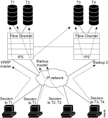
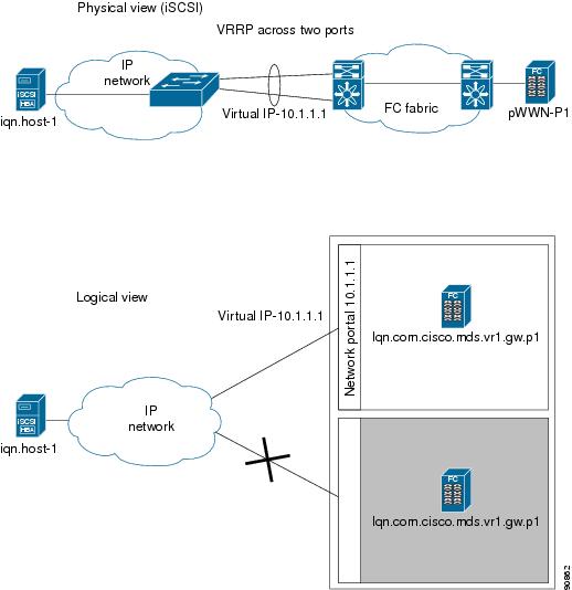
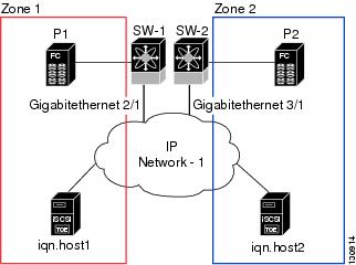
You can configure Virtual Router Redundancy Protocol (VRRP) load balancing for iSLB. Figure 43-14 shows an example of load balancing using iSLB.
Figure 43-14 iSLB Initiator Load Balancing Example
The host is configured with a VRRP address as the portal address. When the VRRP master port receives the first iSCSI session from an initiator, it assigns a backup port to serve that particular host. This information is synchronized to all switches through CFS if recovery is needed when a master port fails. The initiator gets a temporary redirect iSCSI login response. The host then logs in to the backup port at its physical IP address. If the backup port goes down, the host will revert to the master port. The master port knows through CFS that the backup port has gone down and redirects the host to another backup port.
Note
Note
Tip
Caution
Changing iSCSI Interface Parameters and the Impact on Load Balancing
All iSCSI interfaces in a VRRP group that has load balancing enabled must have the same interface VSAN, authentication, proxy initiator mode, and forwarding mode. When you need to change any of these parameters for the iSCSI interfaces in a VRRP group, you must do so one interface at a time. During the transition time when the parameter is changed on some interfaces in the VRRP group and not the others, the master port does not redirect new initiators and instead handles them locally.
Caution
VRRP Load Balancing Algorithm For Selecting Gigabit Ethernet Interfaces
When the VRRP master receives an iSCSI session request from an initiator, it first checks for an existing mapping to one of the interfaces in that VRRP group. If such a mapping exists, the VRRP master redirects the initiator to that interface. If no such mapping exists, the VRRP master selects the least loaded interface and updates the selected interface's load with the initiator's iSLB metric (weight).
Note
VRRP backup interface load > [2 * VRRP master interface load + 1]The Example 43-17 and Example 43-18 are based the following configuration:
•
•
•
•
Example 43-17 Load Distribution With the Default Metric
The follow example output shows the initial load distribution for three initiators with the default load metric value.
switch# show islb vrrp summary...--------------------------------------------------------------------------------VR Id VRRP IP Switch WWN Ifindex Load--------------------------------------------------------------------------------M 1 10.10.122.115 20:00:00:0b:5f:3c:01:80 GigabitEthernet2/1.441 01 10.10.122.115 20:00:00:0b:5f:3c:01:80 GigabitEthernet2/2.441 10001 10.10.122.115 20:00:00:0c:ce:5c:5b:c0 GigabitEthernet1/1.441 10001 10.10.122.115 20:00:00:0c:ce:5c:5b:c0 GigabitEthernet1/2.441 1000-- Initiator To Interface Assignment ----------------------------------------------------------------------------------Initiator VR Id VRRP IP Switch WWN Ifindex--------------------------------------------------------------------------------iqn.cisco.test-linux.init0 1 10.10.122.115 20:00:00:0b:5f:3c:01:80 GigabitEthernet2/2.441iqn.cisco.test-linux.init1 1 10.10.122.115 20:00:00:0c:ce:5c:5b:c0 GigabitEthernet1/1.441iqn.cisco.test-linux.init 1 10.10.122.115 20:00:00:0c:ce:5c:5b:c0 GigabitEthernet1/2.441The following example output shows load distribution for four initiators. The interface load metric value for the master interface changed from 0 to 1000.
switch# show islb vrrp summary...--------------------------------------------------------------------------------VVR Id VRRP IP Switch WWN Ifindex Load--------------------------------------------------------------------------------M 1 10.10.122.115 20:00:00:0b:5f:3c:01:80 GigabitEthernet2/1.441 10001 10.10.122.115 20:00:00:0b:5f:3c:01:80 GigabitEthernet2/2.441 10001 10.10.122.115 20:00:00:0c:ce:5c:5b:c0 GigabitEthernet1/1.441 10001 10.10.122.115 20:00:00:0c:ce:5c:5b:c0 GigabitEthernet1/2.441 1000-- Initiator To Interface Assignment ----------------------------------------------------------------------------------Initiator VR Id VRRP IP Switch WWN Ifindex--------------------------------------------------------------------------------iqn.cisco.test-linux.init0 1 10.10.122.115 20:00:00:0b:5f:3c:01:80 GigabitEthernet2/2.441iqn.cisco.test-linux.init1 1 10.10.122.115 20:00:00:0c:ce:5c:5b:c0 GigabitEthernet1/1.441iqn.cisco.test-linux.init2 1 10.10.122.115 20:00:00:0c:ce:5c:5b:c0 GigabitEthernet1/2.441iqn.cisco.test-linux.init3 1 10.10.122.115 20:00:00:0b:5f:3c:01:80 GigabitEthernet2/1.441The follow example output shows load distribution for nine initiators. The interface load metric values for the backup interfaces have changed.
switch# show islb vrrp summary...--------------------------------------------------------------------------------VVR Id VRRP IP Switch WWN Ifindex Load--------------------------------------------------------------------------------M 1 10.10.122.115 20:00:00:0b:5f:3c:01:80 GigabitEthernet2/1.441 10001 10.10.122.115 20:00:00:0b:5f:3c:01:80 GigabitEthernet2/2.441 30001 10.10.122.115 20:00:00:0c:ce:5c:5b:c0 GigabitEthernet1/1.441 30001 10.10.122.115 20:00:00:0c:ce:5c:5b:c0 GigabitEthernet1/2.441 2000-- Initiator To Interface Assignment ----------------------------------------------------------------------------------Initiator VR Id VRRP IP Switch WWN Ifindex--------------------------------------------------------------------------------iqn.cisco.test-linux.init0 1 10.10.122.115 20:00:00:0b:5f:3c:01:80 GigabitEthernet2/2.441iqn.cisco.test-linux.init1 1 10.10.122.115 20:00:00:0c:ce:5c:5b:c0 GigabitEthernet1/1.441iqn.cisco.test-linux.init2 1 10.10.122.115 20:00:00:0c:ce:5c:5b:c0 GigabitEthernet1/2.441iqn.cisco.test-linux.init3 1 10.10.122.115 20:00:00:0b:5f:3c:01:80 GigabitEthernet2/1.441iqn.cisco.test-linux.init4 1 10.10.122.115 20:00:00:0b:5f:3c:01:80 GigabitEthernet2/2.441iqn.cisco.test-linux.init5 1 10.10.122.115 20:00:00:0c:ce:5c:5b:c0 GigabitEthernet1/1.441iqn.cisco.test-linux.init6 1 10.10.122.115 20:00:00:0c:ce:5c:5b:c0 GigabitEthernet1/2.441iqn.cisco.test-linux.init7 1 10.10.122.115 20:00:00:0b:5f:3c:01:80 GigabitEthernet2/2.441iqn.cisco.test-linux.init8 1 10.10.122.115 20:00:00:0c:ce:5c:5b:c0 GigabitEthernet1/1.441Example 43-18 Load Distribution With the Metric Set to 3000 on One Initiator
The follow example output shows the initial load distribution for three initiators with one initiator having load metric of 3000 and the remaining initiator with the default metric value.
switch# show islb vrrp summary...--------------------------------------------------------------------------------VVR Id VRRP IP Switch WWN Ifindex Load--------------------------------------------------------------------------------M 1 10.10.122.115 20:00:00:0b:5f:3c:01:80 GigabitEthernet2/1.441 01 10.10.122.115 20:00:00:0b:5f:3c:01:80 GigabitEthernet2/2.441 10001 10.10.122.115 20:00:00:0c:ce:5c:5b:c0 GigabitEthernet1/1.441 30001 10.10.122.115 20:00:00:0c:ce:5c:5b:c0 GigabitEthernet1/2.441 1000-- Initiator To Interface Assignment ----------------------------------------------------------------------------------Initiator VR Id VRRP IP Switch WWN Ifindex--------------------------------------------------------------------------------iqn.cisco.test-linux.init0 1 10.10.122.115 20:00:00:0c:ce:5c:5b:c0 GigabitEthernet1/1.441iqn.cisco.test-linux.init1 1 10.10.122.115 20:00:00:0b:5f:3c:01:80 GigabitEthernet2/2.441iqn.cisco.test-linux.init2 1 10.10.122.115 20:00:00:0c:ce:5c:5b:c0 GigabitEthernet1/2.441The follow example output shows load distribution for four initiators. The interface load metric value for the master interface changed from 0 to 1000.
switch# show islb vrrp summary...--------------------------------------------------------------------------------VVR Id VRRP IP Switch WWN Ifindex Load--------------------------------------------------------------------------------M 1 10.10.122.115 20:00:00:0b:5f:3c:01:80 GigabitEthernet2/1.441 10001 10.10.122.115 20:00:00:0b:5f:3c:01:80 GigabitEthernet2/2.441 30001 10.10.122.115 20:00:00:0c:ce:5c:5b:c0 GigabitEthernet1/1.441 10001 10.10.122.115 20:00:00:0c:ce:5c:5b:c0 GigabitEthernet1/2.441 1000-- Initiator To Interface Assignment ----------------------------------------------------------------------------------Initiator VR Id VRRP IP Switch WWN Ifindex--------------------------------------------------------------------------------iqn.cisco.test-linux.init0 1 10.10.122.115 20:00:00:0b:5f:3c:01:80 GigabitEthernet2/2.441iqn.cisco.test-linux.init1 1 10.10.122.115 20:00:00:0c:ce:5c:5b:c0 GigabitEthernet1/2.441iqn.cisco.test-linux.init2 1 10.10.122.115 20:00:00:0c:ce:5c:5b:c0 GigabitEthernet1/1.441iqn.cisco.test-linux.init3 1 10.10.122.115 20:00:00:0b:5f:3c:01:80 GigabitEthernet2/1.441The following example output shows load distribution for nine initiators. The interface load metric values for the backup interfaces have changed.
switch# show islb vrrp summary...--------------------------------------------------------------------------------VVR Id VRRP IP Switch WWN Ifindex Load--------------------------------------------------------------------------------M 1 10.10.122.115 20:00:00:0b:5f:3c:01:80 GigabitEthernet2/1.441 20001 10.10.122.115 20:00:00:0b:5f:3c:01:80 GigabitEthernet2/2.441 30001 10.10.122.115 20:00:00:0c:ce:5c:5b:c0 GigabitEthernet1/1.441 30001 10.10.122.115 20:00:00:0c:ce:5c:5b:c0 GigabitEthernet1/2.441 3000-- Initiator To Interface Assignment ----------------------------------------------------------------------------------Initiator VR Id VRRP IP Switch WWN Ifindex--------------------------------------------------------------------------------iqn.cisco.test-linux.init0 1 10.10.122.115 20:00:00:0b:5f:3c:01:80 GigabitEthernet2/2.441iqn.cisco.test-linux.init1 1 10.10.122.115 20:00:00:0c:ce:5c:5b:c0 GigabitEthernet1/1.441iqn.cisco.test-linux.init2 1 10.10.122.115 20:00:00:0c:ce:5c:5b:c0 GigabitEthernet1/2.441iqn.cisco.test-linux.init3 1 10.10.122.115 20:00:00:0b:5f:3c:01:80 GigabitEthernet2/1.441iqn.cisco.test-linux.init4 1 10.10.122.115 20:00:00:0c:ce:5c:5b:c0 GigabitEthernet1/1.441iqn.cisco.test-linux.init5 1 10.10.122.115 20:00:00:0c:ce:5c:5b:c0 GigabitEthernet1/2.441iqn.cisco.test-linux.init6 1 10.10.122.115 20:00:00:0c:ce:5c:5b:c0 GigabitEthernet1/1.441iqn.cisco.test-linux.init7 1 10.10.122.115 20:00:00:0c:ce:5c:5b:c0 GigabitEthernet1/2.441iqn.cisco.test-linux.init8 1 10.10.122.115 20:00:00:0b:5f:3c:01:80 GigabitEthernet2/1.441Configuring Load Balancing Using VRRP
You must first configure VRRP on the Gigabit Ethernet interfaces on the switch that connect to the IP network before configuring VRRP for iSLB. For information on how to configure VRRP on a Gigabit Ethernet interface, see the "Virtual Router Redundancy Protocol" section on page 44-16.
Enabling VRRP for Load Balancing
To enable or disable VRRP for iSLB, follow these steps:
Verifying iSLB VRRP Load Balancing Configuration
To verify the iSLB VRRP load balancing configuration for IPv4, use the show vrrp vr command.
switch# show vrrp vr 1Interface VR IpVersion Pri Time Pre State VR IP addr---------------------------------------------------------------------------GigE1/5 1 IPv4 100 1 s master 10.10.10.1GigE1/6 1 IPv4 100 1 s master 10.10.10.1To verify the iSLB VRRP load balancing configuration for IPv6, use the show vrrp ipv6 vr command.
switch# show vrrp ipv6 vr 1Interface VR IpVersion Pri Time Pre State VR IP addr--------------------------------------------------------------------GigE6/2 1 IPv6 100 100cs master 5000:1::100PortCh 4 1 IPv6 100 100cs master 5000:1::100Displaying iSLB VRRP Information
Use the show islb vrrp summary vr command to display VRRP load balancing information.
switch# show islb vrrp summary vr 30-- Groups For Load Balance --------------------------------------------------------------------------------------------VR Id VRRP Address Type Configured Status------------------------------------------------------------------------------------------30 IPv4 Enabled-- Interfaces For Load Balance --------------------------------------------------------------------------------------------VR Id VRRP IP Switch WWN Ifindex Load------------------------------------------------------------------------------------------30 192.168.30.40 20:00:00:0d:ec:02:cb:00 GigabitEthernet3/1 200030 192.168.30.40 20:00:00:0d:ec:02:cb:00 GigabitEthernet3/2 200030 192.168.30.40 20:00:00:0d:ec:0c:6b:c0 GigabitEthernet4/1 2000M 30 192.168.30.40 20:00:00:0d:ec:0c:6b:c0 GigabitEthernet4/2 1000About iSLB Configuration Distribution Using CFS
Configuration for iSLB initiators and initiator targets on an MDS switch can be distributed using the Cisco Fabric Services (CFS). This feature allows you to synchronize the iSLB configuration across the fabric from the console of a single MDS switch. The iSCSI initiator idle timeout, iSCSI dynamic initiator mode, and global authentication parameters are also distributed. CFS distribution is disabled by default (see Chapter 5, "Using the CFS Infrastructure").
After enabling the distribution, the first configuration starts an implicit session. All server configuration changes entered thereafter are stored in a temporary database and applied to all switches in the fabric (including the originating one) when you explicitly commit the database.
When CFS is enabled for iSLB, the first iSLB configuration operation starts a CFS session and locks the iSLB configuration in the fabric. The configuration changes are applied to the pending configuration database. When you make the changes to the fabric, the pending configuration is distributed to all the switches in the fabric. Each switch then validates the configuration. This check ensures the following:
•
•
•
After the check completes successfully, all the switches commit the pending configuration to the running configuration. If any check fails, the entire commit fails.
Note
Note
Tip
Distributing the iSLB Configuration Using CFS
This section contains the following:
•
•
•
•
•
Enabling iSLB Configuration Distribution
To enable CFS distribution of the iSLB configuration, follow these steps:
Locking the Fabric
The first action that modifies the existing configuration creates the pending configuration and locks the feature in the fabric. Once you lock the fabric, the following conditions apply:
•
•
Note
Committing Changes to the Fabric
To apply the pending iSLB configuration changes to the active configuration and to other MDS switches in the fabric, you must commit the changes. The pending configuration changes are distributed and, on a successful commit, the configuration changes are applied to the active configuration in the MDS switches throughout the fabric, the automatic zones are activated, and the fabric lock is released.
To commit iSLB configuration changes to other MDS switches in the fabric, activate iSLB automatic zones, and release the fabric lock, follow these steps:
Discarding Pending Changes
At any time, you can discard the pending changes to the iSLB configuration and release the fabric lock. This action has no affect on the active configuration on any switch in the fabric.
To discard the pending iSLB configuration changes and release the fabric lock, follow these steps:
Step 1
switch# config t
Enters configuration mode.
Step 2
switch(config)# islb abort
Commits the iSLB configuration distribution.
Clearing a Fabric Lock
If you have performed an iSLB configuration task and have not released the lock by either committing or discarding the changes, an administrator can release the lock from any switch in the fabric. If the administrator performs this task, your pending changes are discarded and the fabric lock is released.
Tip
To release a fabric lock, issue the clear islb session command in EXEC mode using a login ID that has administrative privileges.
switch# clear islb sessionCFS Merge Process
When two fabrics merge, CFS attempts to merge the iSLB configuration from both the fabrics. A designated switch (called the dominant switch) in one fabric sends its iSLB configuration to a designated switch (called the subordinate switch) in the other fabric. The subordinate switch compares its running configuration to the received configuration for any conflicts. If no conflicts are detected, it merges the two configurations and sends it to all the switches in both the fabrics. Each switch then validates the configuration. This check ensures the following:
•
•
•
If this check completes successfully, the subordinate switch directs all the switches to commit the merged configuration to running configuration. If any check fails, the merge fails.
The show islb merge status command displays the exact reason for the failure. The first successful commit request after a merge failure takes the fabric out of the merge failure state.
Displaying Pending iSLB Configuration Changes
You can display the pending configuration changes using the show islb pending command.
switch# show islb pendingiscsi initiator idle-timeout 10islb initiator ip-address 10.1.1.1static pWWN 23:01:00:0c:85:90:3e:82static pWWN 23:06:00:0c:85:90:3e:82username test1islb initiator ip-address 10.1.1.2static nWWN 23:02:00:0c:85:90:3e:82You can display the differences between the pending configuration and the current configuration using the show islb pending-diff command.
switch# show islb pending-diff+iscsi initiator idle-timeout 10islb initiator ip-address 10.1.1.1+ static pWWN 23:06:00:0c:85:90:3e:82+islb initiator ip-address 10.1.1.2+ static nWWN 23:02:00:0c:85:90:3e:82Displaying iSLB CFS Status
You can display the iSLB CFS status using the show islb session status command.
switch# show islb statusiSLB Distribute is enablediSLB CFS Session existsDisplaying iSLB CFS Distribution Session Status
You can display the status of the iSLB CFS distribution session using the show islb cfs-session status command.
switch# show islb cfs-session statuslast action : fabric distribute enablelast action result : successlast action failure cause : successDisplaying iSLB CFS Merge Status
You can display the iSLB CFS merge status using the show islb merge status command.
switch# show islb merge statusMerge Status: SuccessMerge conflicts may occur. User intervention is required for the following merge conflicts:
•
•
•
•
•
Tip
User intervention is not required when the same iSLB initiator has a different set of non-conflicting initiator targets. The merged configuration is the union of all the initiator targets.
iSCSI High Availability
The following high availability features are available for iSCSI configurations:
•
•
Transparent Target Failover
The following high availability configurations are available:
•
•
iSCSI High Availability with Host Running Multi-Path Software
Figure 43-15 shows the physical and logical topology for an iSCSI HA solution for hosts running multi-path software. In this scenario, the host has four iSCSI sessions. There are two iSCSI sessions from each host NIC to the two IPS ports.
Figure 43-15 Host Running Multi-Path Software
Each IPS ports is exporting the same two Fibre Channel target ports of the storage but as different iSCSI target names if you use dynamic iSCSI targets). So the two IPS ports are exporting a total of four iSCSI target devices. These four iSCSI targets map the same two ports of the Fibre Channel target.
The iSCSI host uses NIC-1 to connect to IPS port 1 and NIC-2 to connect to IPS port 2. Each IPS port exports two iSCSI targets, so the iSCSI host creates four iSCSI sessions.
If the iSCSI host NIC-1 fails (see Figure 43-15 for the physical view), then sessions 1 and 2 fail but we still have sessions 3 and 4.
If the IPS port 1 fails, the iSCSI host cannot connect to the IPS port, and sessions 1 and 2 fail. But sessions 3 and 4 are still available.
If the storage port 1 fails, then the IPS ports will terminate sessions 1 and 3 (put iSCSI virtual target iqn.com.cisco.mds-5.1-2.p1 and iqn-com.cisco.mds-5.1-1.p1 in offline state). But sessions 2 and 4 are still available.
In this topology, you have recovery from failure of any of the components. The host multi-path software takes care of load-balancing or failover across the different paths to access the storage.
iSCSI HA with Host Not Having Any Multi-Path Software
The above topology will not work if the host does not have multi-path software because the host has multiple sessions to the same storage. Without multi-path software the host does not have knowledge of the multiple paths to the same storage.
IP storage has two additional features that provide an HA solution in this scenario.
•
•
Statically imported iSCSI targets have an additional option to provide a secondary pWWN for the Fibre Channel target. This can be used when the physical Fibre Channel target is configured to have an LU visible across redundant ports. When the active port fails, the secondary port becomes active and the iSCSI session switches to use the new active port (see Figure 43-16).
Figure 43-16 Static Target Importing Through Two Fibre Channel Ports
In Figure 43-16, you can create an iSCSI virtual target that is mapped to both pWWN1 and pWWN2 to provide redundant access to the Fibre Channel targets.
The failover to a secondary port is done transparently by the IPS port without impacting the iSCSI session from the host. All outstanding I/Os are terminated with a check condition status when the primary port fails. New I/Os received during the failover are not completed and receive a busy status.
Tip
Enable the optional revert-primary-port option to direct the IPS port to switch back to the primary port when the primary port is up again. If this option is disabled (default) and the primary port is up again after a switchover, the old sessions will remain with the secondary port and do not switch back to the primary port. However, any new session will use the primary port. This is the only situation when both the primary and secondary ports are used at the same time.
To create a static iSCSI virtual target, follow these steps:
LUN Trespass for Storage Port Failover
In addition to the high availability of statically imported iSCSI targets, the trespass feature is available to enable the move of LUs, on an active port failure, from the active to the passive port of a statically imported iSCSI target.
In physical Fibre Channel targets, which are configured to have LUs visible over two Fibre Channel N ports, when the active port fails, the passive port takes over. Some physical Fibre Channel targets require that the trespass feature be used to move the LUs from the active port to the passive port. A statically imported iSCSI target's secondary pWWN option and an additional option of enabling the trespass feature is available for a physical Fibre Channel target with redundant ports. When the active port fails, the passive port becomes active, and if the trespass feature is enabled, the Cisco MDS switch sends a request to the target to move the LUs on the new active port. The iSCSI session switches to use the new active port and the moved LUs are accessed over the new active port (see Figure 43-17).
Figure 43-17 Virtual Target with an Active Primary Port
To enable the trespass feature for a static iSCSI virtual target, follow these steps:
Use the show iscsi virtual-target command to verify.
switch# show iscsi virtual-target iqn.1987-02.com.cisco.initiatortarget: 1987-02.com.cisco.initiatorPort WWN 10:20:10:00:56:00:70:50Configured nodeall initiator permit is disabledtrespass support is enabledMultiple IPS Ports Connected to the Same IP Network
Figure 43-18 provides an example of a configuration with multiple Gigabit Ethernet interfaces in the same IP network.
Figure 43-18 Multiple Gigabit Ethernet Interfaces in the Same IP Network
In Figure 43-18, each iSCSI host discovers two iSCSI targets for every physical Fibre Channel target (with different names). The multi-pathing software on the host provides load-balancing over both paths. If one Gigabit Ethernet interface fails, the host multi-pathing software is not affected because it can use the second path.
VRRP-Based High Availability
Figure 43-19 provides an example of a VRRP-based high availability iSCSI configuration.
Figure 43-19 VRRP-Based iSCSI High Availability
In Figure 43-19, each iSCSI host discovers one iSCSI target for every physical Fibre Channel target. When the Gigabit Ethernet interface of the VRRP master fails, the iSCSI session is terminated. The host then reconnects to the target and the session comes up because the second Gigabit Ethernet interface has taken over the virtual IP address as the new master.
Ethernet PortChannel-Based High Availability
Note
Figure 43-20 provides a sample Ethernet PortChannel-based high availability iSCSI configuration.
Figure 43-20 Ethernet PortChannel-Based iSCSI High Availability
In Figure 43-20, each iSCSI host discovers one iSCSI target for every physical Fibre Channel target. The iSCSI session from the iSCSI host to the iSCSI virtual target (on the IPS port) uses one of the two physical interfaces (because an iSCSI session uses one TCP connection). When the Gigabit Ethernet interface fails, the IPS module and the Ethernet switch transparently forwards all the frames on to the second Gigabit Ethernet interface.
Note
iSCSI Authentication Setup Guidelines and Scenarios
This section provides guidelines on iSCSI authentication possibilities, setup requirements, and sample scenarios. It includes the following authentication setup guidelines:
•
•
•
•
Note
Caution
No Authentication
Set the iSCSI authentication method to none to configure a network with no authentication.
switch(config)# iscsi authentication noneCHAP with Local Password Database
To configure authentication using the CHAP option with the local password database, follow these steps:
Step 1
switch(config)# aaa authentication iscsi default localStep 2
switch(config)# iscsi authentication chapStep 3
switch(config)# username iscsi-user password abcd iscsi
Note
Step 4
switch# show iscsi globaliSCSI Global information Authentication: CHAP <----VerifyImport FC Target: Disabled...
CHAP with External RADIUS Server
To configure authentication using the CHAP option with an external RADIUS server, follow these steps:
Step 1
switch(config)# radius-server key mds-1Step 2
Configure an IPv4 address.
switch(config)# radius-server host 10.1.1.10Configure an IPv6 address.
switch(config)# radius-server host 2001:0DB8:800:200C::417AStep 3
Configure an IPv4 address.
switch(config)# aaa group server radius iscsi-radius-groupswitch(config-radius)# server 10.1.1.1Configure an IPv6 address.
switch(config)# aaa group server radius iscsi-radius-groupswitch(config-radius)# server 001:0DB8:800:200C::4180switch(config)# aaa authentication iscsi default group iscsi-radius-groupStep 4
switch(config)# iscsi authentication chapStep 5
switch# show iscsi globaliSCSI Global informationAuthentication: CHAP <---------------- Verify CHAP....Step 6
switch# show aaa authenticationdefault: localconsole: localiscsi: group iscsi-radius-group <--------- Group namedhchap: localswitch# show radius-server groupstotal number of groups:2following RADIUS server groups are configured:group radius:server: all configured radius serversgroup iscsi-radius-group:server: 10.1.1.1 on auth-port 1812, acct-port 1813switch# show radius-serverGlobal RADIUS shared secret:mds-1 <-------- Verify secret....following RADIUS servers are configured:10.1.1.1: <----------- Verify the server IPv4 addressavailable for authentication on port:1812available for accounting on port:1813To configure an iSCSI RADIUS server, follow these steps:
Step 1
Step 2
Step 3
iSCSI Transparent Mode Initiator
This scenario assumes the following configuration (see Figure 43-21):
•
•
•
–
–
–
–
Figure 43-21 iSCSI Scenario 1
To configure scenario 1 (see Figure 43-21), follow these steps:
Step 1
switch(config)# iscsi authentication noneStep 2
switch(config)# iscsi import target fcStep 3
switch(config)# interface gigabitethernet 7/1switch(config-if)# ip address 10.11.1.1 255.255.255.0switch(config-if)# no shutdown
Note
Step 4
switch(config)# interface iscsi 7/1switch(config-if)# switchport initiator id ip-addressswitch(config-if)# no shutStep 5
switch(config)# interface gigabitethernet 7/5switch(config-if)# ip address 10.15.1.1 255.255.255.0switch(config-if)# no shutdownStep 6
switch(config)# interface iscsi 7/5switch(config-if)# switchport initiator id nameswitch(config-if)# no shutdown
Note
Step 7
switch# show fcns databaseVSAN 1:--------------------------------------------------------------------------FCID TYPE PWWN (VENDOR) FC4-TYPE:FEATURE--------------------------------------------------------------------------0x6d0001 NL 21:00:00:20:37:6f:fd:97 (Seagate) scsi-fcp:target0x6d0101 NL 21:00:00:20:37:6f:fe:54 (Seagate) scsi-fcp:target0x6d0201 NL 21:00:00:20:37:a6:a6:5d (Seagate) scsi-fcp:targetTotal number of entries = 3Step 8
Note
switch(config)# zone name iscsi-zone-1 vsan 1switch(config-zone)# member pwwn 21:00:00:20:37:6f:fd:97switch(config-zone)# member ip-address 10.11.1.10Step 9
Note
switch(config)# zone name iscsi-zone-2 vsan 1switch(config-zone)# member pwwn 21:00:00:20:37:6f:fe:54switch(config-zone)# member pwwn 21:00:00:20:37:a6:a6:5dswitch(config-zone)# member symbolic-nodename iqn.1987-05.com.cisco:01.25589167f74cStep 10
switch(config)# zoneset name zoneset-iscsi vsan 1switch(config-zoneset)# member iscsi-zone-1switch(config-zoneset)# member iscsi-zone-2Step 11
switch(config)# zoneset activate name zoneset-iscsi vsan 1Step 12
Note
switch# show zoneset activezoneset name zoneset-iscsi vsan 1zone name iscsi-zone-1 vsan 1* fcid 0x6d0001 [pwwn 21:00:00:20:37:6f:fd:97] <-----------Targetsymbolic-nodename 10.11.1.10 <--------------------------------- iSCSI host (host 1, not online)zone name iscsi-zone-2 vsan 1* fcid 0x6d0101 [pwwn 21:00:00:20:37:6f:fe:54] <------------Target* fcid 0x6d0201 [pwwn 21:00:00:20:37:a6:a6:5d] <------------Targetsymbolic-nodename iqn.1987-05.com.cisco:01.25589167f74c <-iSCSI host (host 2, not online)Step 13
Step 14
switch# show iscsi sessionInitiator iqn.1987-05.com.cisco:01.25589167f74c <-----Host 2Initiator ip addr (s): 10.15.1.11Session #1Target iqn.1987-05.com.cisco:05.172.22.92.166.07-05.21000020376ffe54
Note
VSAN 1, ISID 00023d000001, Status active, no reservationSession #2Target iqn.1987-05.com.cisco:05.172.22.92.166.07-05.2100002037a6a65dVSAN 1, ISID 00023d000001, Status active, no reservationInitiator 10.11.1.10 <-----------------------------------Host 1Initiator name iqn.1987-05.com.cisco:01.e41695d16b1aSession #1Target iqn.1987-05.com.cisco:05.172.22.92.166.07-01.21000020376ffd97VSAN 1, ISID 00023d000001, Status active, no reservationStep 15
Step 16
Step 17
switch# show fcns databaseVSAN 1:--------------------------------------------------------------------------FCID TYPE PWWN (VENDOR) FC4-TYPE:FEATURE--------------------------------------------------------------------------0x6d0001 NL 21:00:00:20:37:6f:fd:97 (Seagate) scsi-fcp:target0x6d0101 NL 21:00:00:20:37:6f:fe:54 (Seagate) scsi-fcp:target0x6d0201 NL 21:00:00:20:37:a6:a6:5d (Seagate) scsi-fcp:target0x6d0300 N 20:03:00:0b:fd:44:68:c2 (Cisco) scsi-fcp:init isc..w0x6d0301 N 20:05:00:0b:fd:44:68:c2 (Cisco) scsi-fcp:init isc..wStep 18
Target Storage Device Requiring LUN Mapping
Sample scenario 2 assumes the following configuration (see Figure 43-22):
•
•
•
•
Figure 43-22 iSCSI Scenario 2
To configure scenario 2 (see Figure 43-22), follow these steps:
Step 1
switch(config)# iscsi authentication noneStep 2
switch(config)# iscsi import target fcStep 3
switch(config)# interface gigabitethernet 7/1switch(config-if)# ip address 10.11.1.1 255.255.255.0switch(config-if)# no shutdownStep 4
switch(config)# interface iscsi 7/1switch(config-if)# switchport initiator id ip-addressswitch(config-if)# no shutdownStep 5
switch(config)# interface gigabitethernet 7/5switch(config-if)# ip address 10.15.1.1 255.255.255.0switch(config-if)# no shutdownStep 6
switch(config)# interface iscsi 7/5switch(config-if)# switchport initiator id ip-addressswitch(config-if)# no shutdownStep 7
switch(config)# iscsi initiator name iqn.1987-05.com.cisco:01.e41695d16b1a <-----Host 2switch(config-iscsi-init)# static pWWN system-assign 1switch(config-iscsi-init)# static nWWN system-assignswitch(config)# iscsi initiator ip address 10.15.1.11 <-----------------------------------Host 1switch(config-iscsi-init)# static pwwn system-assigned 1switch(config-iscsi-init)# vsan 2
Note
Step 8
Note
switch# show iscsi initiator configurediSCSI Node name is iqn.1987-05.com.cisco:01.e41695d16b1aMember of vsans: 1Node WWN is 20:03:00:0b:fd:44:68:c2No. of PWWN: 1Port WWN is 20:02:00:0b:fd:44:68:c2iSCSI Node name is 10.15.1.11Member of vsans: 2No. of PWWN: 1Port WWN is 20:06:00:0b:fd:44:68:c2Step 9
switch(config)# zone name iscsi-zone-1 vsan 1Step 10
Note
•
switch(config-zone)# member symbolic-nodename iqn.1987-05.com.cisco:01.e41695d16b1a•
switch(config-zone)# member pwwn 20:02:00:0b:fd:44:68:c2Step 11
Note
switch(config)# zone name iscsi-zone-2 vsan 2Step 12
switch(config)# zoneset activate name iscsi-zoneset-v2 vsan 2Zoneset activation initiated. check zone statusswitch# show zoneset active vsan 2zoneset name iscsi-zoneset-v2 vsan 2zone name iscsi-zone-2 vsan 2* fcid 0x750001 [pwwn 21:00:00:20:37:6f:fe:54]* fcid 0x750101 [pwwn 21:00:00:20:37:a6:a6:5d]pwwn 20:06:00:0b:fd:44:68:c2 <-----------------Host is not onlineStep 13
Step 14
Step 15
Step 16
Step 17
Step 18
Step 19
switch(config)# show fcns database fcid 0x680102 detail vsan 1------------------------VSAN:1 FCID:0x680102------------------------port-wwn (vendor) :20:02:00:0b:fd:44:68:c2 (Cisco)node-wwn :20:03:00:0b:fd:44:68:c2class :2,3node-ip-addr :10.11.1.10ipa :ff ff ff ff ff ff ff fffc4-types:fc4_features:scsi-fcp:init iscsi-gwsymbolic-port-name :symbolic-node-name :iqn.1987-05.com.cisco:01.e41695d16b1aport-type :Nport-ip-addr :0.0.0.0fabric-port-wwn :21:81:00:0b:fd:44:68:c0hard-addr :0x000000Step 20
switch# show zoneset active vsan 1zoneset name iscsi-zoneset-v1 vsan 1zone name iscsi-zone-1 vsan 1* fcid 0x680001 [pwwn 21:00:00:20:37:6f:fd:97]* fcid 0x680102 [pwwn 20:02:00:0b:fd:44:68:c2]Step 21
iSNS
Internet Storage Name Service (iSNS) allows your existing TCP/IP network to function more effectively as a SAN by automating the discovery, management, and configuration of iSCSI devices. To facilitate these functions, the iSNS server and client function as follows:
•
•
–
–
–
All iSCSI devices (both initiator and target) acting as iSNS clients, can register with an iSNS server. iSCSI initiators can then query the iSNS server for a list of targets. The iSNS server will respond with a list of targets that the querying client can access based on configured access control parameters.
A Cisco MDS 9000 Family switch can act as an iSNS client and register all available iSCSI targets with an external iSNS server. All switches in the Cisco MDS 9000 Family with IPS modules or MPS-14/2 modules installed support iSNS server functionality. This allows external iSNS clients, such as an iSCSI initiator, to register with the switch and discover all available iSCSI targets in the SAN.
This section includes the following topics:
•
•
•
About iSNS Client Functionality
The iSNS client functionality on each IPS interface (Gigabit Ethernet interface or subinterface or PortChannel) registers information with an iSNS server. You must specify an iSNS server's IP address by creating an iSNS profile, adding the server's IP address to it, and then assigning (or "tagging") the profile to the interface. An iSNS profile can be tagged to one or more interfaces.
Once a profile is tagged to an interface, the switch opens a TCP connection to the iSNS server IP address (using the well-known iSNS port number 3205) in the profile and registers network entity and portal objects; a unique entity is associated with each IPS interface. The switch then searches the Fibre Channel name server (FCNS) database and switch configuration to find storage nodes to register with the iSNS server.
Statically mapped virtual targets are registered if the associated Fibre Channel pWWN is present in the FCNS database and no access control configuration prevents it. A dynamically mapped target is registered if dynamic target importing is enabled. See the "Presenting Fibre Channel Targets as iSCSI Targets" section for more details on how iSCSI imports Fibre Channel targets.
A storage node is deregistered from the iSNS server when it becomes unavailable when a configuration changes (such as access control change or dynamic import disabling) or the Fibre Channel storage port goes offline. It is registered again when the node comes back online.
When the iSNS client is unable to register or deregister objects with the iSNS server (for example, the client is unable to make a TCP connection to the iSNS server), it retries every minute to reregister all iSNS objects for the affected interfaces with the iSNS server. The iSNS client uses a registration interval value of 15 minutes. If the client fails to refresh the registration during this interval, the server will deregister the entries.
Untagging a profile also causes the network entity and portal to be deregistered from that interface.
Note
Creating an iSNS Client Profile
To create an iSNS profile, follow these steps:
To remove an iSNS profile, follow these steps:
Step 1
switch# config t
switch(config)#
Enters configuration mode.
Step 2
switch(config)# no isns profile name OldIsns
Removes a configured iSNS profile called OldIsns.
To tag a profile to an interface, follow these steps:
To untag a profile from an interface, follow these steps:
Use the isns reregister command in EXEC mode to re-register associated iSNS objects with the iSNS server.
switch# isns reregister gigabitethernet 1/4switch# isns reregister port-channel 1Verifying iSNS Client Configuration
Use the show isns profile command to view configured iSNS profiles. Profile ABC has two portals registered with the iSNS server. Each portal corresponds to a particular interface. Profile XYZ has a specified iSNS server, but does not have any tagged interfaces configured (see Example 43-19 and Example 43-20).
Example 43-19 Displays Information for Configured iSNS Profiles
switch# show isns profileiSNS profile name ABCtagged interface GigabitEthernet2/3tagged interface GigabitEthernet2/2iSNS Server 10.10.100.204iSNS profile name XYZiSNS Server 10.10.100.211Example 43-20 Displays a Specified iSNS Profile
switch# show isns profile ABCiSNS profile name ABCtagged interface GigabitEthernet2/3tagged interface GigabitEthernet2/2iSNS Server 10.10.100.204Use the show isns profile counters command to view all configured profiles with the iSNS PDU statistics for each tagged interface (see Example 43-21 and Example 43-22).
Example 43-21 Displays Configured Profiles with iSNS Statistics
switch# show isns profile countersiSNS profile name ABCtagged interface port-channel 1iSNS statisticsInput 54 pdus (registration/deregistration pdus only)Reg pdus 37, Dereg pdus 17Output 54 pdus (registration/deregistration pdus only)Reg pdus 37, Dereg pdus 17iSNS Server 10.10.100.204iSNS profile name XYZtagged interface port-channel 2iSNS statisticsInput 30 pdus (registration/deregistration pdus only)Reg pdus 29, Dereg pdus 1Output 30 pdus (registration/deregistration pdus only)Reg pdus 29, Dereg pdus 1iSNS Server 10.1.4.218Example 43-22 Displays iSNS Statistics for a Specified Profile
switch# show isns profile ABC countersiSNS profile name ABCtagged interface port-channel 1iSNS statisticsInput 54 pdus (registration/deregistration pdus only)Reg pdus 37, Dereg pdus 17Output 54 pdus (registration/deregistration pdus only)Reg pdus 37, Dereg pdus 17iSNS Server 10.10.100.204Use the show isns command to view all objects registered on the iSNS server and specified in the given profile (see Example 43-23).
Example 43-23 Displays iSNS Queries
switch# show isns query ABC gigabitethernet 2/3iSNS server: 10.10.100.204Init: iqn.1991-05.com.w2kAlias: <MS SW iSCSI Initiator>Tgt : iqn.1987-05.com.cisco:05.172.22.94.22.02-03Tgt : iqn.1987-05.com.cisco:05.172.22.94.22.02-03.210000203762fa34nWWN: 200000203762fa34Use the show interface command to view the iSNS profile to which an interface is tagged (see Example 43-24).
Example 43-24 Displays Tagged iSNS Interfaces
switch# show interface gigabitethernet 2/3
    GigabitEthernet2/3 is up
    Hardware is GigabitEthernet, address is 0005.3000.ae94
Internet address is 10.10.100.201/24MTU 1500 bytesPort mode is IPSSpeed is 1 GbpsBeacon is turned offAuto-Negotiation is turned oniSNS profile ABC^^^^^^^^^^^^^^^^5 minutes input rate 112 bits/sec, 14 bytes/sec, 0 frames/sec5 minutes output rate 0 bits/sec, 0 bytes/sec, 0 frames/sec1935 packets input, 132567 bytes4 multicast frames, 0 compressed0 input errors, 0 frame, 0 overrun 0 fifo1 packets output, 42 bytes, 0 underruns0 output errors, 0 collisions, 0 fifo0 carrier errorsAbout iSNS Server Functionality
When enabled, the iSNS server on the Cisco 9000 Family MDS switch tracks all registered iSCSI devices. As a result, iSNS clients can locate other iSNS clients by querying the iSNS server. The iSNS server also provides the following functionalities:
•
•
•
•
•
Example Scenario
The iSNS server provides uniform access control across Fibre Channel and iSCSI devices by utilizing both Fibre Channel zoning information and iSCSI access control information and configuration. An iSCSI initiator acting as an iSNS client only discovers devices it is allowed to access based on both sets of access control information. Figure 43-23 provides an example of this scenario.
Figure 43-23 Using iSNS Servers in the Cisco MDS Environment
In Figure 43-23, iqn.host1 and iqn.host2 are iSCSI initiators. P1 and P2 are Fibre Channel targets. The two initiators are in different zones: Zone 1 consists of iqn.host1 and target P1, and Zone 2 consists of iqn.host2 and target P2. iSNS server functionality is enabled on both switches, SW-1 and SW-2. The registration process proceeds as follows:
1.
2.
3.
4.
5.
6.
7.
8.
Configuring iSNS Servers
This section describe how to configure an iSNS server on a Cisco MDS 9000 Family switch.
This section includes the following topics:
•
•
•
•
•
Enabling the iSNS Server
Before the iSNS server feature can be enabled, iSCSI must be enabled (see the "Enabling iSCSI" section). When you disable iSCSI, iSNS is automatically disabled. When the iSNS server is enabled on a switch, every IPS port whose corresponding iSCSI interface is up is capable of servicing iSNS registration and query requests from external iSNS clients.
To enable the iSNS server, follow these steps:
Note
iSNS Configuration Distribution
You can use the CFS infrastructure to distribute the iSCSI initiator configuration to iSNS servers across the fabric. This allows the iSNS server running on any switch to provide a querying iSNS client a list of iSCSI devices available anywhere on the fabric. For information on CFS, see Chapter 7, "Using the CFS Infrastructure."
To enable iSNS configuration distribution using, follow these steps:
Configuring the ESI Retry Count
The iSNS client registers information with its configured iSNS server using an iSNS profile. At registration, the client can indicate an entity status inquiry (ESI) interval of 60 seconds or more. If the client registers with an ESI interval set to zero (0), then the server does not monitor the client using ESI. In such cases, the client's registrations remain valid until explicitly deregistered or the iSNS server feature is disabled.
The ESI retry count is the number of times the iSNS server queries iSNS clients for their entity status. The default ESI retry count is 3. The client sends the server a response to indicate that it is still alive. If the client fails to respond after the configured number of retries, the client is deregistered from the server.
To configure the ESI retry count for an iSNS server, follow these steps:
Configuring the Registration Period
The iSNS client specifies the registration period with the iSNS Server. The iSNS Server keeps the registration active until the end of this period. If there are no commands from the iSNS client during this period, then the iSNS server removes the client registration from its database.
If the iSNS client does not specify a registration period, the iSNS server assumes a default value of 0, which keeps the registration active indefinitely. You can also manually configure the registration period on the MDS iSNS Server.
To configure the registration period on an iSNS Server, follow these steps:
iSNS Client Registration and Deregistration
An iSNS client cannot query the iSNS server until it has registered. You can use the show isns database command to display all registered iSNS clients and their associated configuration.
iSNS client deregistration can occur either explicitly or when the iSNS server detects that it can no longer reach the client (through ESI monitoring).
iSNS client registration and deregistration result in status change notifications (SCNs) being generated to all interested iSNS clients.
Target Discovery
iSCSI initiators discover targets by issuing queries to the iSNS server. The server supports DevGetNext requests to search the list of targets and DevAttrQuery to determine target and portal details, such as the IP address or port number to which to connect.
On receiving a query request from the iSCSI client, the iSNS server queries the Fibre Channel Name Server (FCNS) to obtain a list of Fibre Channel targets that are accessible by the querying initiator. The result of this query depends on zoning configuration currently active and current configuration(s) of the initiator. The iSNS server will subsequently use the iSCSI target configuration(s) (virtual target and dynamic import configuration) to translate the Fibre Channel target to an equivalent iSCSI target. At this stage it also applies any access control configured for the virtual target. A response message with the target details is then sent back to the query initiator.
The iSNS server sends a consolidated response containing all possible targets and portals to the querying initiator. For example, if a Fibre Channel target is exported as different iSCSI targets on different IPS interfaces, the iSNS server will respond with a list of all possible iSCSI targets and portals.
In order to keep the list of targets updated, the iSNS server sends state change notifications (SCN) to the client whenever an iSCSI target becomes reachable or unreachable. The client is then expected to rediscover its list of accessible targets by initiating another iSNS query. Reachability of iSCSI targets changes when any one of the following occurs:
•
•
•
•
•
•
Verifying the iSNS Server Configuration
Use the show isns config command to view the ESI interval and the summary information about the iSNS database contents (see Example 43-25).
Example 43-25 Displays the iSNS Server Configuration of ESI Interval and Database Contents
switch# show isns configServer Name: switch1(Cisco Systems) Up since: Fri Jul 30 04:08:16 2004Index: 1 Version: 1 TCP Port: 3205fabric distribute (remote sync): ONESINon Response Threshold: 5 Interval(seconds): 60Database contentsNumber of Entities: 2Number of Portals: 3Number of ISCSI devices: 4Number of Portal Groups: 0Use the show isns database command to view detailed information about the contents of the iSNS database (see Example 43-26 through Example 43-29). This command displays the full iSNS database giving all the entities, nodes, and portals registered in the database. This command without options only displays explicitly registered objects. The asterisk next to the VSAN ID indicates that the iSCSI node is in the default zone for that VSAN.
Example 43-26 Displays Explicitly Registered Objects
switch# show isns databaseEntity Id: dp-204Index: 2 Last accessed: Fri Jul 30 04:08:46 2004iSCSI Node Name: iqn.1991-05.comdp-2041Entity Index: 2Node Type: Initiator(2) Node Index: 0x1SCN Bitmap: OBJ_UPDATED|OBJ ADDED|OBJ REMOVED|TARGET&SELFNode Alias: <MS SW iSCSI Initiator>VSANS: 1(*), 5(*)Portal IP Address: 192.168.100.2 TCP Port: 4179Entity Index: 2 Portal Index: 1ESI Interval: 0 ESI Port: 4180 SCN Port: 4180Example 43-27 displays information about both virtual and registered iSCSI initiators/targets.
Example 43-27 Displays the Full Database with Both Registered and Configured Nodes and Portals
switch# show isns database fullEntity Id: isns.entity.mds9000Index: 1 Last accessed: Fri Jul 30 04:08:16 2004iSCSI Node Name: iqn.com.cisco.disk1Entity Index: 1Node Type: Target(1) Node Index: 0x80000001WWN(s):22:00:00:20:37:39:dc:45VSANS:iSCSI Node Name: iqn.isns-first-virtual-targetEntity Index: 1Node Type: Target(1) Node Index: 0x80000002VSANS:iSCSI Node Name: iqn.com.cisco.disk2Entity Index: 1Node Type: Target(1) Node Index: 0x80000003WWN(s):22:00:00:20:37:39:dc:45VSANS:Portal IP Address: 192.168.100.5 TCP Port: 3205Entity Index: 1 Portal Index: 3Portal IP Address: 192.168.100.6 TCP Port: 3205Entity Index: 1 Portal Index: 5Entity Id: dp-204Index: 2 Last accessed: Fri Jul 30 04:08:46 2004iSCSI Node Name: iqn.1991-05.com.microsoft:dp-2041Entity Index: 2Node Type: Initiator(2) Node Index: 0x1SCN Bitmap: OBJ_UPDATED|OBJ ADDED|OBJ REMOVED|TARGET&SELFNode Alias: <MS SW iSCSI Initiator>VSANS: 1(*), 5(*)Portal IP Address: 192.168.100.2 TCP Port: 4179Entity Index: 2 Portal Index: 1ESI Interval: 0 ESI Port: 4180 SCN Port: 4180Example 43-28 displays the virtual targets entries on the current switch.
Note
Example 43-28 Displays the Virtual Target Information in the Local Switch
switch# show isns database virtual-targets localEntity Id: isns.entity.mds9000Index: 1 Last accessed: Fri Jul 30 04:08:16 2004iSCSI Node Name: iqn.com.cisco.disk1Entity Index: 1Node Type: Target(1) Node Index: 0x80000001WWN(s):22:00:00:20:37:39:dc:45VSANS:iSCSI Node Name: iqn.isns-first-virtual-targetEntity Index: 1Node Type: Target(1) Node Index: 0x80000002VSANS:iSCSI Node Name: iqn.com.cisco.disk2Entity Index: 1Node Type: Target(1) Node Index: 0x80000003WWN(s):22:00:00:20:37:39:dc:45VSANS:Portal IP Address: 192.168.100.5 TCP Port: 3205Entity Index: 1 Portal Index: 3Portal IP Address: 192.168.100.6 TCP Port: 3205Entity Index: 1 Portal Index: 5Example 43-29 provides the virtual target information for a specific remote switch. The remote switch is specified using the switch ID (the WWN of the switch).
Example 43-29 Displays Virtual Target for a Specified Switch
switch# show isns database virtual-targets switch 20:00:00:0d:ec:01:04:40Entity Id: isns.entity.mds9000Index: 1 Last accessed: Fri Jul 30 04:08:16 2004iSCSI Node Name: iqn.com.cisco.disk1Entity Index: 1Node Type: Target(1) Node Index: 0x80000001WWN(s):22:00:00:20:37:39:dc:45VSANS:iSCSI Node Name: iqn.isns-first-virtual-targetEntity Index: 1Node Type: Target(1) Node Index: 0x80000002VSANS:iSCSI Node Name: iqn.com.cisco.disk2Entity Index: 1Node Type: Target(1) Node Index: 0x80000003WWN(s):22:00:00:20:37:39:dc:45VSANS:Portal IP Address: 192.168.100.5 TCP Port: 3205Entity Index: 1 Portal Index: 3Portal IP Address: 192.168.100.6 TCP Port: 3205Entity Index: 1 Portal Index: 5Use the show isns node command to display attributes of nodes registered with the iSNS server (see Example 43-30 through Example 43-32). If you do not specify any options, the server displays the name and node type attribute in a compact format; one per line.
Example 43-30 Displays Explicitly Registered Objects
switch# show isns node all-------------------------------------------------------------------------------iSCSI Node Name Type-------------------------------------------------------------------------------iqn.1987-05.com.cisco:05.switch1.02-03.22000020375a6c8 Target...iqn.com.cisco.disk1 Targetiqn.com.cisco.ipdisk Targetiqn.isns-first-virtual-target Targetiqn.1991-05.cw22 Targetiqn.1991-05.cw53 TargetExample 43-31 Displays the Specified Node
switch# show isns node name iqn.com.cisco.disk1iSCSI Node Name: iqn.com.cisco.disk1Entity Index: 1Node Type: Target(1) Node Index: 0x80000001WWN(s):22:00:00:20:37:39:dc:45VSANS: 1Example 43-32 Displays the Attribute Details for All Nodes
switch# show isns node all detailiSCSI Node Name: iqn.1987-05.com.cisco:05.switch1.02-03.22000020375a6c8fEntity Index: 1Node Type: Target(1) Node Index: 0x3000003Configured Switch WWN: 20:00:00:0d:ec:01:04:40WWN(s):22:00:00:20:37:5a:6c:8fVSANS: 1...iSCSI Node Name: iqn.com.cisco.disk1Entity Index: 1Node Type: Target(1) Node Index: 0x80000001Configured Switch WWN: 20:00:00:0d:ec:01:04:40WWN(s):22:00:00:20:37:39:dc:45VSANS: 1iSCSI Node Name: iqn.com.cisco.ipdiskEntity Index: 1Node Type: Target(1) Node Index: 0x80000002Configured Switch WWN: 20:00:00:0d:ec:01:04:40WWN(s):22:00:00:20:37:5a:70:1aVSANS: 1iSCSI Node Name: iqn.isns-first-virtual-targetEntity Index: 1Node Type: Target(1) Node Index: 0x80000003Configured Switch WWN: 20:00:00:0d:ec:01:04:40iSCSI Node Name: iqn.parna.121212Entity Index: 1Node Type: Target(1) Node Index: 0x80000004Configured Switch WWN: 20:00:00:0d:ec:01:04:40iSCSI Node Name: iqn.parna.121213Entity Index: 1Node Type: Target(1) Node Index: 0x80000005Configured Switch WWN: 20:00:00:0d:ec:01:04:40Use the show isns portal command to display the attributes of a portal along with its accessible nodes (see Example 43-33 through Example 43-37). You can specify portals by using the switch WWN-interface combination or the IP address-port number combination.
Example 43-33 Displays the Attribute Information for All Portals
switch# show isns portal all-------------------------------------------------------------------------------IPAddress TCP Port Index SCN Port ESI port-------------------------------------------------------------------------------192.168.100.5 3205 3 - -192.168.100.6 3205 5 - -Example 43-34 Displays Detailed Attribute Information for All Portals
switch# show isns portal all detailPortal IP Address: 192.168.100.5 TCP Port: 3205Entity Index: 1 Portal Index: 3Portal IP Address: 192.168.100.6 TCP Port: 3205Entity Index: 1 Portal Index: 5Example 43-35 Displays Virtual Portals
switch# show isns portal virtual-------------------------------------------------------------------------------IPAddress TCP Port Index SCN Port ESI port-------------------------------------------------------------------------------192.168.100.5 3205 3 - -192.168.100.6 3205 5 - -Example 43-36 Displays Virtual Portals for the Specified Switch
switch# show isns portal virtual switch 20:00:00:0d:ec:01:04:40-------------------------------------------------------------------------------IPAddress TCP Port Index SCN Port ESI port-------------------------------------------------------------------------------192.168.100.5 3205 3 - -192.168.100.6 3205 5 - -Example 43-37 Displays Detailed Information for the Virtual Portals in the Specified Switch
switch# show isns portal virtual switch 20:00:00:0d:ec:01:04:40 detailPortal IP Address: 192.168.100.5 TCP Port: 3205Entity Index: 1 Portal Index: 3Switch WWN: 20:00:00:0d:ec:01:04:40Interface: GigabitEthernet2/3Portal IP Address: 192.168.100.6 TCP Port: 3205Entity Index: 1 Portal Index: 5Switch WWN: 20:00:00:0d:ec:01:04:40Interface: GigabitEthernet2/5Use the show isns entity command to display the attributes of an entity along with the list of portals and nodes in that entity (see Example 43-38 through Example 43-42). If you do not specify any option, this command displays the entity ID and number of nodes or portals associated with the entity in a compact format; one per line.
Example 43-38 Displays All Registered Entries
switch1# show isns entity-------------------------------------------------------------------------------Entity ID Last Accessed-------------------------------------------------------------------------------dp-204 Tue Sep 7 23:15:42 2004Example 43-39 Displays All Entities in the Database
switch# show isns entity all-------------------------------------------------------------------------------Entity ID Last Accessed-------------------------------------------------------------------------------isns.entity.mds9000 Tue Sep 7 21:33:23 2004dp-204 Tue Sep 7 23:15:42 2004Example 43-40 Displays the Entity with the Specified ID
switch1# show isns entity id dp-204Entity Id: dp-204Index: 2 Last accessed: Tue Sep 7 23:15:42 2004Example 43-41 Displays Detailed Information for All Entities in the Database
switch1# show isns entity all detailEntity Id: isns.entity.mds9000Index: 1 Last accessed: Tue Sep 7 21:33:23 2004Entity Id: dp-204Index: 2 Last accessed: Tue Sep 7 23:16:34 2004Example 43-42 Displays Virtual Entities
switch# show isns entity virtualEntity Id: isns.entity.mds9000Index: 1 Last accessed: Thu Aug 5 00:58:50 2004Entity Id: dp-204Index: 2 Last accessed: Thu Aug 5 01:00:23 2004Use the show iscsi global config command to display information about import targets (see Example 43-43 and Example 43-44).
Example 43-43 Displays the Import Target Settings for the Specified Switch
switch# show isns iscsi global config switch 20:00:00:05:ec:01:04:00iSCSI Global configuration:Switch: 20:00:00:05:ec:01:04:00 iSCSI Auto Import: EnabledExample 43-44 Displays the Import Target Settings for All Switches
switch# show isns iscsi global config alliSCSI Global configuration:Switch: 20:00:44:0d:ec:01:02:40 iSCSI Auto Import: EnabledUse the show cfs peers command to display CFS peers switch information about the iSNS application (see Example 43-45).
Example 43-45 Displays the CFS Peer Switch Information for the iSNS Application
switch# show cfs peers name isnsScope : Physical--------------------------------------------------Switch WWN IP Address--------------------------------------------------20:00:00:00:ec:01:00:40 10.10.100.11 [Local]Total number of entries = 1iSNS Cloud Discovery
You can configure iSNS cloud discovery to automate the process of discovering iSNS servers in the IP network.
This section includes the following topics:
•
•
•
•
About Cloud Discovery
Note
When an iSNS server receives a query request, it responds with a list of available targets and the portals through which the initiator can reach the target. The IP network configuration outside the MDS switch may result in only a subset of Gigabit Ethernet interfaces being reachable from the initiator. To ensure that the set of portals returned to the initiator is reachable, the iSNS server needs to know the set of Gigabit Ethernet interfaces that are reachable from a given initiator.
The iSNS cloud discovery feature provides information to the iSNS server on the various interfaces reachable from an initiator by partitioning the interfaces on a switch into disjointed IP clouds. This discovery is achieved by sending messages to all other known IPS ports that are currently up and, depending on the response (or the lack of it), determines if the remote IPS port is in the same IP network or in a different IP network.
Cloud discovery is initiated when the following events occur:
•
•
–
–
–
The iSNS server distributes cloud and membership information across all the switches using CFS. Therefore, the cloud membership view is the same on all the switches in the fabric.
Note
Configuring iSNS Cloud Discovery
This section describes how to configure iSNS cloud discovery and includes the following topics:
•
•
•
•
•
•
Enabling iSNS Cloud Discovery
To enable iSNS cloud discovery, follow these steps:
Initiating On-Demand iSNS Cloud Discovery
To initiate on-demand iSNS cloud discovery, use the cloud discover command in EXEC mode.
The following example shows how to initiate on-demand cloud discovery for the entire fabric:
switch# cloud discoverConfiguring Automatic iSNS Cloud Discovery
To configure automatic iSNS cloud discovery, follow these steps:
Verifying Automatic iSNS Cloud Discovery Configuration
To verify the automatic iSNS cloud discovery configuration, use the show cloud discovery config command.
switch# show cloud discovery configAuto discovery: EnabledConfiguring iSNS Cloud Discovery Distribution
To configure iSNS cloud discovery distribution using CFS, follow these steps:
Configuring iSNS Cloud Discovery Message Types
You can configure iSNS cloud discovery the type of message to use. By default, iSNS cloud discovery uses ICMP.
To configure iSNS cloud discovery message types, follow these steps:
Verifying Cloud Discovery Status
Use the show cloud discovery status command to verify the status of the cloud discovery operation.
switch# show cloud discovery statusDiscovery status: SucceededVerifying Cloud Discovery Membership
Use the show cloud membership all command to verify the cloud membership for the switch.
switch# show cloud membership allCloud 2GigabitEthernet1/5[20:00:00:0d:ec:02:c6:c0] IP Addr 10.10.10.5GigabitEthernet1/6[20:00:00:0d:ec:02:c6:c0] IP Addr 10.10.10.6#members=2Use the show cloud membership unresolved command to verify the unresolved membership on the switch.
switch# show cloud membership unresolvedUndiscovered CloudNo membersDisplaying Cloud Discovery Statistics
Use the show cloud discovery statistics command to display the statistics for the cloud discovery operation.
switch# show cloud discovery statisticsGlobal statisticsNumber of Auto Discovery = 1Number of Manual Discovery = 0Number of cloud discovery (ping) messages sent = 1Number of cloud discovery (ping) success = 1Default Settings
Table 43-2 lists the default settings for iSCSI parameters.
Table 43-3 lists the default settings for iSLB parameters.
Table 43-3 Default iSLB Parameters
Fabric distribution
Disabled.
Load balancing metric
1000.