-
Cisco MDS 9000 Family CLI Configuration Guide, Release 3.3(3)
-
Index
-
New and Changed Information
-
Preface
- Getting Started
- Installation and Switch Management
- Switch Configuration
-
Fabric Configuration
-
Configuring and Managing VSANs
-
SAN Device Virtualization
-
Creating Dynamic VSANs
-
Configuring Inter-VSAN Routing
-
Distributing Device Alias Services
-
Configuring Fibre Channel Routing Services and Protocols
-
Managing FLOGI, Name Server, FDMI, and RSCN Databases
-
Discovering SCSI Targets
-
Configuring FICON
-
Advanced Features and Concepts
-
Configuring and Managing Zones
-
-
Security
-
Configuring FIPS
-
Configuring Users and Common Roles
-
Configuring SNMP
-
Configuring RADIUS and TACACS+
-
Configuring IPv4 and IPv6 Access Control Lists
-
Configuring Certificate Authorities and Digital Certificates
-
Configuring IPsec Network Security
-
Configuring FC-SP and DHCHAP
-
Configuring Port Security
-
Configuring Fabric Binding
-
- IP Services
- Intelligent Storage Services
- Network and Switch Monitoring
- Traffic Management
- Troubleshooting
-
Configuration Limits for Cisco MDS SAN-OS Release 3.x
-
 Feedback
Table Of Contents
Generation 1 Interfaces Configuration Guidelines
N Port Identifier Virtualization
Configuring Fibre Channel Interfaces
Setting the Interface Administrative State
Configuring System Default Port Mode F
Enabling N Port Identifier Virtualization
Configuring the Interface Description
Configuring Receive Data Field Size
Switch Port Attribute Default Values
Displaying Interface Information
Displaying TL Port Information
Manually Inserting Entries into ALPA Cache
Displaying the ALPA Cache Contents
About Buffer-to-Buffer Credits
Configuring Buffer-to-Buffer Credits
Configuring Performance Buffers
Extended BB_credits on Generation 1 Switching Modules
Extended BB_credits on Generation 2 Switching Modules
Configuring Extended BB_credits
Displaying BB_Credit Information
Configuring Management Interfaces
Displaying Management Interface Configuration
Displaying VSAN Interface Information
Configuring Interfaces
A switch's main function is to relay frames from one data link to another. To do that, the characteristics of the interfaces through which the frames are received and sent must be defined. The configured interfaces can be Fibre Channel interfaces, Gigabit Ethernet interfaces, the management interface (mgmt0), or VSAN interfaces.
This chapter describes the basic interface configuration to get your switch up and running. It includes the following sections:
See Chapter 5, "Initial Configuration," and Chapter 44, "Configuring IP Services," for more information on configuring mgmt0 interfaces.
See Chapter 46, "Configuring IPv4 for Gigabit Ethernet Interfaces" and Chapter 47, "Configuring IPv6 for Gigabit Ethernet Interfaces"for more information on configuring Gigabit Ethernet interfaces.
Tip
Before you begin configuring the switch, ensure that the modules in the chassis are functioning as designed. To verify the status of a module at any time, issue the show module command in EXEC mode (see the "Verifying the Module Status" section on page 5-15).
Fibre Channel Interfaces
This section describes Fibre Channel interface characteristics, including (but not limited to) modes, frame encapsulation, states, SFPs, and speeds.
This section includes the following topics:
•
•
•
•
•
•
•
•
•
Generation 1 Interfaces Configuration Guidelines
The generation 1 interfaces configuration guidelines apply to the following hardware:
•
•
When configuring these host-optimized ports, the following port mode guidelines apply:
•
•
•
•
•
•
Note
Note
About Interface Modes
Each physical Fibre Channel interface in a switch may operate in one of several port modes: E port, F port, FL port, TL port, TE port, SD port, ST port, and B port (see Figure 13-1). Besides these modes, each interface may be configured in auto or Fx port modes. These two modes determine the port type during interface initialization.
Figure 13-1 Cisco MDS 9000 Family Switch Port Modes
Note
Each interface has an associated administrative configuration and an operational status:
•
•
Note
A brief description of each interface mode follows.
E Port
In expansion port (E port) mode, an interface functions as a fabric expansion port. This port may be connected to another E port to create an Inter-Switch Link (ISL) between two switches. E ports carry frames between switches for configuration and fabric management. They serve as a conduit between switches for frames destined to remote N ports and NL ports. E ports support class 2, class 3, and class F service.
An E port connected to another switch may also be configured to form a PortChannel (see Chapter 17, "Configuring PortChannels").
Note
F Port
In fabric port (F port) mode, an interface functions as a fabric port. This port may be connected to a peripheral device (host or disk) operating as an N port. An F port can be attached to only one N port. F ports support class 2 and class 3 service.
FL Port
In fabric loop port (FL port) mode, an interface functions as a fabric loop port. This port may be connected to one or more NL ports (including FL ports in other switches) to form a public arbitrated loop. If more than one FL port is detected on the arbitrated loop during initialization, only one FL port becomes operational and the other FL ports enter nonparticipating mode. FL ports support class 2 and class 3 service.
Note
NP Ports
An NP port is a port on a device that is in NPV mode and connected to the core switch via a F port. NP ports behave like N ports except that in addition to providing N port behavior, they also function as proxies for multiple, physical N ports.
For more details about NP ports and NPV, see Chapter 14, "Configuring N Port Virtualization."
TL Port
In translative loop port (TL port) mode, an interface functions as a translative loop port. It may be connected to one or more private loop devices (NL ports). TL ports are specific to Cisco MDS 9000 Family switches and have similar properties as FL ports. TL ports enable communication between a private loop device and one of the following devices:
•
•
•
•
TL ports support class 2 and class 3 services.
Private loop devices refer to legacy devices that reside on arbitrated loops. These devices are not aware of a switch fabric because they only communicate with devices on the same physical loop (see the "About TL Port ALPA Caches" section).
Tip
Note
TE Port
In trunking E port (TE port) mode, an interface functions as a trunking expansion port. It may be connected to another TE port to create an extended ISL (EISL) between two switches. TE ports are specific to Cisco MDS 9000 Family switches. They expand the functionality of E ports to support the following:
•
•
•
In TE port mode, all frames are transmitted in EISL frame format, which contains VSAN information. Interconnected switches use the VSAN ID to multiplex traffic from one or more VSANs across the same physical link. This feature is referred to as trunking in the Cisco MDS 9000 Family (see Chapter 16, "Configuring Trunking"). TE ports support class 2, class 3, and class F service.
SD Port
In SPAN destination port (SD port) mode, an interface functions as a switched port analyzer (SPAN). The SPAN feature is specific to switches in the Cisco MDS 9000 Family. It monitors network traffic that passes though a Fibre Channel interface. This monitoring is done using a standard Fibre Channel analyzer (or a similar switch probe) that is attached to an SD port. SD ports do not receive frames, they merely transmit a copy of the source traffic. The SPAN feature is nonintrusive and does not affect switching of network traffic for any SPAN source ports (see Chapter 53, "Monitoring Network Traffic Using SPAN").
ST Port
In the SPAN tunnel port (ST port) mode, an interface functions as an entry point port in the source switch for the RSPAN Fibre Channel tunnel. The ST port mode and the remote SPAN (RSPAN) feature are specific to switches in the Cisco MDS 9000 Family. When configured in ST port mode, the interface cannot be attached to any device, and thus cannot be used for normal Fibre Channel traffic (see the "Configuring SPAN" section on page 53-6).
Note
Fx Port
Interfaces configured as Fx ports can operate in either F port or FL port mode. The Fx port mode is determined during interface initialization depending on the attached N port or NL port. This administrative configuration disallows interfaces to operate in any other mode—for example, preventing an interface to connect to another switch.
B Port
While E ports typically interconnect Fibre Channel switches, some SAN extender devices, such as the Cisco PA-FC-1G Fibre Channel port adapter, implement a bridge port (B port) model to connect geographically dispersed fabrics. This model uses B ports as described in the T11 Standard FC-BB-2.
Figure 13-1 depicts a typical SAN extension over an IP network.
If an FCIP peer is a SAN extender device that only supports Fibre Channel B ports, you need to enable the B port mode for the FCIP link. When a B port is enabled, the E port functionality is also enabled and they coexist. If the B port is disabled, the E port functionality remains enabled (see Chapter 45, "Configuring IP Storage").
Auto Mode
Interfaces configured in auto mode can operate in one of the following modes: F port, FL port, E port, or TE port. The port mode is determined during interface initialization. For example, if the interface is connected to a node (host or disk), it operates in F port or FL port mode depending on the N port or NL port mode. If the interface is attached to a third-party switch, it operates in E port mode. If the interface is attached to another switch in the Cisco MDS 9000 Family, it may become operational in TE port mode (see Chapter 16, "Configuring Trunking").
TL ports and SD ports are not determined during initialization and are administratively configured.
Note
N Port Identifier Virtualization
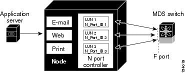
N port identifier virtualization (NPIV) provides a means to assign multiple FC IDs to a single N port. This feature allows multiple applications on the N port to use different identifiers and allows access control, zoning, and port security to be implemented at the application level. Figure 13-2 shows an example application using NPIV.
Figure 13-2 NPIV Example
You must globally enable NPIV for all VSANs on the MDS switch to allow the NPIV-enabled applications to use multiple N port identifiers.
Note
About Interface States
The interface state depends on the administrative configuration of the interface and the dynamic state of the physical link.
Administrative States
The administrative state refers to the administrative configuration of the interface as described in Table 13-1.
Operational States
The operational state indicates the current operational state of the interface as described in Table 13-2.
Reason Codes
Reason codes are dependent on the operational state of the interface as described in Table 13-3.
Table 13-3 Reason Codes for Interface States
Up
Up
None.
Down
Down
Administratively down—If you administratively configure an interface as down, you disable the interface. No traffic is received or transmitted.
Up
Down
See Table 13-4.
Note
If the administrative state is up and the operational state is down, the reason code differs based on the nonoperational reason code as described in Table 13-4.
Configuring Fibre Channel Interfaces
To configure a Fibre Channel interface, follow these steps:
To configure a range of interfaces, follow these steps:
For the Cisco Fabric Switch for HP c-Class BladeSystem and the Cisco Fabric Switch for IBM BladeCenter, you can configure a range of interfaces among internal ports or external ports, but you cannot mix both interface types within the same range. For example, "bay 1-10, bay 12" or "ext 0, ext 15-18" are valid ranges, but "bay 1-5, ext 15-17" is not.
Graceful Shutdown
Interfaces on a port are shutdown by default (unless you modified the initial configuration).
The Cisco SAN-OS software implicitly performs a graceful shutdown in response to either of the following actions for interfaces operating in the E port mode:
•
•
A graceful shutdown ensures that no frames are lost when the interface is shutting down. When a shutdown is triggered either by you or the Cisco SAN-OS software, the switches connected to the shutdown link coordinate with each other to ensure that all frames in the ports are safely sent through the link before shutting down. This enhancement reduces the chance of frame loss.
A graceful shutdown is not possible in the following situations:
•
•
•
Note
Setting the Interface Administrative State
To gracefully shut down an interface, follow these steps:
To enable traffic flow, follow these steps:
Configuring Interface Modes
To configure the interface mode, follow these steps:
Configuring System Default Port Mode F
The system default switchport mode F command sets the administrative mode of all Fibre Channel ports to mode F, while avoiding traffic disruption caused by the formation of unwanted inter-switch links (ISLs). This command is part of the setup utility that runs during bootup after a write erase or reload. It can also be executed from the command line in configuration mode. This command changes the configuration of the following ports to administrative mode F:
•
•
This command does not affect the configuration of the following ports:
•
•
Example 13-1 shows the command in the setup utility, and Example 13-2 shows the command from the command line.
Example 13-1 Setup Utility
Configure default switchport mode F (yes/no) [n]: yExample 13-2 Command Line
switch(config)# system default switchport mode F
Note
Note
To sets the administrative mode of Fibre Channel ports to mode F in the CLI, follow these steps:
Note
Configuring Port Speeds
By default, the portspeed for an interface is automatically calculated by the switch.
Caution
To configure the port speed of the interface, follow these steps:
For internal ports on the Cisco Fabric Switch for HP c_Class BladeSystem and Cisco Fabric Switch for IBM BladeCenter a port speed of 1 Gbps is not supported. Auto-negotiation is supported between 2 Gbps and 4 Gbps only. Also, if the BladeCenter is a "T" chassis, then port speeds are fixed at 2 Gbps and auto-negotiation is not enabled.
Autosensing
Autosensing speed is enabled on all 4-Gbps switching module interfaces by default. This configuration enables the interfaces to operate at speeds of 1 Gbps, 2 Gbps, or 4 Gbps on the 4-Gbps switching modules. When autosensing is enabled for an interface operating in dedicated rate mode, 4-Gbps of bandwidth is reserved, even if the port negotiates at an operating speed of 1-Gbps or 2-Gbps.
To avoid wasting unused bandwidth on 48-port and 24-port 4-Gbps Fibre Channel switching modules, you can specify that only 2 Gbps of required bandwidth be reserved, not the default of 4 Gbps. This feature shares the unused bandwidth within the port group provided that it does not exceed the rate limit configuration for the port. You can also use this feature for shared rate ports that are configured for autosensing.
Tip
Enabling N Port Identifier Virtualization
You must globally enable NPIV for all VSANs on the MDS switch to allow the NPIV-enabled applications to use multiple N port identifiers.
Note
To enable or disable NPIV on the switch, follow these steps:
About Interface Descriptions
Interface descriptions should help you identify the traffic or use for that interface. The interface description can be any alphanumeric string.
Configuring the Interface Description
To configure a description for an interface, follow these steps:
About Frame Encapsulation
The switchport encap eisl command only applies to SD port interfaces. This command determines the frame format for all frames transmitted by the interface in SD port mode. If the encap is set to EISL, all outgoing frames are transmitted in the EISL frame format, irrespective of the SPAN source(s).
The switchport encap eisl command is disabled by default. If you enable encapsulation, all outgoing frames are encapsulated, and you will see a new line (Encapsulation is eisl) in the show interface SD_port_interface command output (see the "Encapsulating Frames" section on page 53-11).
About Receive Data Field Size
You can also configure the receive data field size for Fibre Channel interfaces. If the default data field size is 2112 bytes, the frame length will be 2148 bytes.
Configuring Receive Data Field Size
You can also configure the receive data field size for Fibre Channel interfaces. If the default data field size is 2112 bytes, the frame length will be 2148 bytes.
To configure the receive data field size, follow these steps:
Identifying the Beacon LEDs
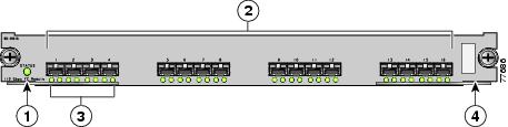
Figure 13-3 displays the status, link, and speed LEDs in a 16-port switching module.
Figure 13-3 Cisco MDS 9000 Family Switch Interface Modes
Status LED1
Link LEDs1 and speed LEDs2
1/2-Gbps Fibre Channel port group3
Asset tag4
1 See the "Identifying Module LEDs" section on page 12-9.
2 See the "About Speed LEDs" section.
3 See the "32-Port Switching Module Configuration Guidelines" section on page 13-2.
4 Refer to the Cisco MDS 9000 Family hardware installation guide for your platform.
About Speed LEDs
Each port has one link LED on the left and one speed LED on the right.
The speed LED displays the speed of the port interface:
•
•
The speed LED also displays if the beacon mode is enabled or disabled:
•
•
About Beacon Mode
By default, the beacon mode is disabled on all switches. The beacon mode is indicated by a flashing green light that helps you identify the physical location of the specified interface.
Configuring the beacon mode has no effect on the operation of the interface.
Configuring Beacon Mode
To enable beacon mode for a specified interface or range of interfaces, follow these steps:
Note
About Bit Error Thresholds
The bit error rate threshold is used by the switch to detect an increased error rate before performance degradation seriously affects traffic.
The bit errors can occur for the following reasons:
•
•
•
•
•
•
•
•
A bit error rate threshold is detected when 15 error bursts occur in a 5-minute period. By default, the switch disables the interface when the threshold is reached. You can issue shutdown/no shutdown command sequence to reenable the interface.
You can configure the switch to not disable an interface when the threshold is crossed. By default, the threshold disables the interface.
To disable the bit error threshold for an interface, follow these steps:
Note
Switch Port Attribute Default Values
You can configure attribute default values for various switch port attributes. These attributes will be applied globally to all future switch port configurations, even if you do not individually specify them at that time.
To configure switch port attributes, follow these steps:
About SFP Transmitter Types
The small form-factor pluggable (SFP) hardware transmitters are identified by their acronyms when displayed in the show interface brief command. If the related SFP has a Cisco-assigned extended ID, then the show interface and show interface brief commands display the ID instead of the transmitter type. The show interface transceiver command and the show interface fcslot/port transceiver command display both values for Cisco supported SFPs. Table 13-5 defines the acronyms used in the command output (see the "Displaying Interface Information" section).
Displaying Interface Information
The show interface command is invoked from the EXEC mode and displays the interface configurations. Without any arguments, this command displays the information for all the configured interfaces in the switch. See Examples 13-3 to 13-10.
Example 13-3 Display All Interfaces
switch# show interfacefc1/1 is upHardware is Fibre Channel, SFP is short wave laserPort WWN is 20:0b:00:05:30:00:8d:deAdmin port mode is FPort mode is F, FCID is 0x610000Port vsan is 2Speed is 2 GbpsTransmit B2B Credit is 3Receive B2B Credit is 16Receive data field Size is 2112Beacon is turned off5 minutes input rate 0 bits/sec, 0 bytes/sec, 0 frames/sec5 minutes output rate 0 bits/sec, 0 bytes/sec, 0 frames/sec134 frames input, 8468 bytes0 discards, 0 errors0 CRC, 0 unknown class0 too long, 0 too short154 frames output, 46072 bytes0 discards, 0 errors1 input OLS, 1 LRR, 0 NOS, 0 loop inits1 output OLS, 0 LRR, 1 NOS, 0 loop inits16 receive B2B credit remaining3 transmit B2B credit remaining.. . .fc1/9 is trunkingHardware is Fibre Channel, SFP is long wave laser cost reducedPort WWN is 20:09:00:05:30:00:97:9ePeer port WWN is 20:0b:00:0b:5f:a3:cc:00Admin port mode is E, trunk mode is onPort mode is TEPort vsan is 100Speed is 2 GbpsTransmit B2B Credit is 255Receive B2B Credit is 255Receive data field Size is 2112Beacon is turned offTrunk vsans (admin allowed and active) (1,100,3000)Trunk vsans (up) (1,100,3000)Trunk vsans (isolated) ()Trunk vsans (initializing) ()5 minutes input rate 280 bits/sec, 35 bytes/sec, 0 frames/sec5 minutes output rate 176 bits/sec, 22 bytes/sec, 0 frames/sec4609939 frames input, 8149405708 bytes0 discards, 0 errors0 CRC, 0 unknown class0 too long, 0 too short4638491 frames output, 7264731728 bytes0 discards, 0 errors3 input OLS, 9 LRR, 1 NOS, 0 loop inits9 output OLS, 7 LRR, 1 NOS, 0 loop inits16 receive B2B credit remaining3 transmit B2B credit remaining.. . .fc1/13 is upHardware is Fibre Channel, SFP is short wave laserPort WWN is 20:0d:00:05:30:00:97:9eAdmin port mode is auto, trunk mode is onPort mode is F, FCID is 0x650100Port vsan is 100Speed is 2 GbpsTransmit B2B Credit is 3Receive B2B Credit is 16Receive data field Size is 2112Beacon is turned off5 minutes input rate 0 bits/sec, 0 bytes/sec, 0 frames/sec5 minutes output rate 0 bits/sec, 0 bytes/sec, 0 frames/sec8696 frames input, 3227212 bytes0 discards, 0 errors0 CRC, 0 unknown class0 too long, 0 too short16799 frames output, 6782444 bytes0 discards, 0 errors0 input OLS, 0 LRR, 0 NOS, 0 loop inits1 output OLS, 1 LRR, 0 NOS, 1 loop inits16 receive B2B credit remaining3 transmit B2B credit remaining.. . .sup-fc0 is upHardware is Fibre ChannelSpeed is 1 Gbps139597 packets input, 13852970 bytes0 multicast frames, 0 compressed0 input errors, 0 frame, 0 overrun 0 fifo139516 packets output, 16759004 bytes, 0 underruns0 output errors, 0 collisions, 0 fifo0 carrier errorsYou can also specify arguments (a range of interfaces or multiple, specified interfaces) to display interface information. You can specify a range of interfaces by issuing a command with the following example format:
interface fc1/1 - 5 , fc2/5 - 7
Note
Example 13-4 Display Multiple, Specified Interfaces
switch# show interface fc3/13 , fc3/16fc3/13 is upHardware is Fibre Channel, SFP is short wave laserPort WWN is 20:8d:00:05:30:00:97:9eAdmin port mode is FXPort mode is F, FCID is 0x7b0300Port vsan is 1Speed is 2 GbpsTransmit B2B Credit is 3Receive B2B Credit is 12Receive data field Size is 2112Beacon is turned off5 minutes input rate 0 bits/sec, 0 bytes/sec, 0 frames/sec5 minutes output rate 0 bits/sec, 0 bytes/sec, 0 frames/sec1856 frames input, 116632 bytes0 discards, 0 errors0 CRC, 0 unknown class0 too long, 0 too short1886 frames output, 887712 bytes0 discards, 0 errors0 input OLS, 0 LRR, 0 NOS, 1 loop inits1 output OLS, 1 LRR, 0 NOS, 1 loop inits16 receive B2B credit remaining3 transmit B2B credit remaining.fc3/16 is upHardware is Fibre Channel, SFP is short wave laserPort WWN is 20:90:00:05:30:00:97:9eAdmin port mode is FXPort mode is F, FCID is 0x7d0100Port vsan is 3000Speed is 2 GbpsTransmit B2B Credit is 3Receive B2B Credit is 12Receive data field Size is 2112Beacon is turned off5 minutes input rate 504 bits/sec, 63 bytes/sec, 0 frames/sec5 minutes output rate 520 bits/sec, 65 bytes/sec, 0 frames/sec47050 frames input, 10311824 bytes0 discards, 0 errors0 CRC, 0 unknown class0 too long, 0 too short62659 frames output, 10676988 bytes0 discards, 0 errors0 input OLS, 0 LRR, 0 NOS, 0 loop inits1 output OLS, 1 LRR, 0 NOS, 1 loop inits16 receive B2B credit remaining3 transmit B2B credit remaining.Example 13-5 Display a Specific Interface
switch# show interface fc2/2fc2/2 is trunkingPort description is Trunk to Core-4Hardware is Fibre Channel, SFP is short wave laserPort WWN is 20:42:00:05:30:00:97:9ePeer port WWN is 20:cc:00:05:30:00:50:9eAdmin port mode is E, trunk mode is onPort mode is TEPort vsan is 1Speed is 2 GbpsTransmit B2B Credit is 255Receive B2B Credit is 255Receive data field Size is 2112Beacon is turned offBelongs to port-channel 2Trunk vsans (admin allowed and active) (1,100,3000)Trunk vsans (up) (1)Trunk vsans (isolated) (100,3000)Trunk vsans (initializing) ()5 minutes input rate 0 bits/sec, 0 bytes/sec, 0 frames/sec5 minutes output rate 32 bits/sec, 4 bytes/sec, 0 frames/sec2214834 frames input, 98673588 bytes0 discards, 0 errors0 CRC, 0 unknown class0 too long, 0 too short2262415 frames output, 343158368 bytes0 discards, 0 errors1 input OLS, 1 LRR, 1 NOS, 0 loop inits2 output OLS, 1 LRR, 0 NOS, 0 loop inits16 receive B2B credit remaining3 transmit B2B credit remaining.Example 13-6 Displays Port Description
switch# show interface description-------------------------------------------------------------------------------Interface Description-------------------------------------------------------------------------------fc3/1 test intestfc3/2 --fc3/3 --fc3/4 TE portfc3/5 --fc3/6 --fc3/10 Next hop switch 5fc3/11 --fc3/12 --fc3/16 ---------------------------------------------------------------------------------Interface Description-------------------------------------------------------------------------------port-channel 1 --port-channel 5 --port-channel 6 --Example 13-7 Display Interface Information in a Brief Format
switch# show interface brief-------------------------------------------------------------------------------Interface Vsan Admin Admin Status SFP Oper Oper PortMode Trunk Mode Speed ChannelMode (Gbps)-------------------------------------------------------------------------------fc1/1 1 E on trunking swl TE 2 1fc1/2 1 E on trunking swl TE 2 1fc1/3 1 auto on SFPAbsent -- -- --fc1/4 1 auto on SFPAbsent -- -- --fc1/5 3000 auto on up swl F 2 --...fc2/2 1 E on trunking swl TE 2 2fc2/3 1 auto on down c1610 -- --fc2/4 1 auto on down c1590 -- --fc2/5 3000 auto on notConnected lwcr -- --fc2/6 1 auto on SFPAbsent -- -- --...fc3/16 3000 FX -- up swl F 2 --fc3/17 1 FX -- SFPAbsent -- -- --...-------------------------------------------------------------------------------Interface Status IP Address Speed MTU-------------------------------------------------------------------------------GigabitEthernet4/1 SFPAbsent -- auto 1500...GigabitEthernet4/6 down 10.1.1.2/8 auto 3000GigabitEthernet4/7 down 10.1.1.27/24 auto 1500GigabitEthernet4/8 down -- auto 1500-------------------------------------------------------------------------------Interface Status Oper Mode Oper Speed(Gbps)-------------------------------------------------------------------------------iscsi4/1 down --...-------------------------------------------------------------------------------Interface Status Speed(Gbps)-------------------------------------------------------------------------------sup-fc0 up 1-------------------------------------------------------------------------------Interface Status IP Address Speed MTU-------------------------------------------------------------------------------mgmt0 up 172.19.48.96/25 100 Mbps 1500-------------------------------------------------------------------------------Interface Vsan Admin Status Oper OperTrunk Mode SpeedMode (Gbps)-------------------------------------------------------------------------------port-channel 1 1 on trunking TE 4port-channel 2 1 on trunking TE 4-------------------------------------------------------------------------------Interface Vsan Admin Admin Status Oper Profile Port-channelMode Trunk ModeMode-------------------------------------------------------------------------------fcip10 1 auto on notConnected -- 10 --Example 13-8 Display Interface Counters
switch# show interface countersfc3/15 minutes input rate 24 bits/sec, 3 bytes/sec, 0 frames/sec5 minutes output rate 16 bits/sec, 2 bytes/sec, 0 frames/sec3502 frames input, 268400 bytes0 discards, 0 CRC, 0 unknown class0 too long, 0 too short3505 frames output, 198888 bytes0 discards1 input OLS, 1 LRR, 1 NOS, 0 loop inits2 output OLS, 1 LRR, 1 NOS, 0 loop inits1 link failures, 1 sync losses, 1 signal losses...fc9/85 minutes input rate 0 bits/sec, 0 bytes/sec, 0 frames/sec5 minutes output rate 0 bits/sec, 0 bytes/sec, 0 frames/sec0 frames input, 0 bytes0 class-2 frames, 0 bytes0 class-3 frames, 0 bytes0 class-f frames, 0 bytes0 discards, 0 CRC, 0 unknown class0 too long, 0 too short0 frames output, 0 bytes0 class-2 frames, 0 bytes0 class-3 frames, 0 bytes0 class-f frames, 0 bytes0 discards0 input OLS, 0 LRR, 0 NOS, 0 loop inits0 output OLS, 0 LRR, 0 NOS, 0 loop inits0 link failures, 0 sync losses, 0 signal losses16 receive B2B credit remaining3 transmit B2B credit remaining.. . .sup-fc0114000 packets input, 11585632 bytes0 multicast frames, 0 compressed0 input errors, 0 frame, 0 overrun 0 fifo113997 packets output, 10969672 bytes, 0 underruns0 output errors, 0 collisions, 0 fifo0 carrier errorsmgmt031557 packets input, 2230860 bytes0 multicast frames, 0 compressed0 input errors, 0 frame, 0 overrun 0 fifo26618 packets output, 16824342 bytes, 0 underruns0 output errors, 0 collisions, 7 fifo0 carrier errorsvsan10 packets input, 0 bytes, 0 errors, 0 multicast0 packets output, 0 bytes, 0 errors, 0 dropped...port-channel 15 minutes input rate 0 bits/sec, 0 bytes/sec, 0 frames/sec5 minutes output rate 0 bits/sec, 0 bytes/sec, 0 frames/sec0 frames input, 0 bytes0 class-2 frames, 0 bytes0 class-3 frames, 0 bytes0 class-f frames, 0 bytes0 discards, 0 CRC, 0 unknown class0 too long, 0 too short0 frames output, 0 bytes0 class-2 frames, 0 bytes0 class-3 frames, 0 bytes0 class-f frames, 0 bytes0 discards0 input OLS, 0 LRR, 0 NOS, 0 loop inits0 output OLS, 0 LRR, 0 NOS, 0 loop inits0 link failures, 0 sync losses, 0 signal losses
Note
Example 13-9 Display Interface Counters in Brief Format
switch# show interface counters brief-------------------------------------------------------------------------------Interface Input (rate is 5 min avg) Output (rate is 5 min avg)----------------------------- -----------------------------Rate Total Rate TotalMbits/s Frames Mbits/s Frames-------------------------------------------------------------------------------fc3/1 0 3871 0 3874fc3/2 0 3902 0 4232fc3/3 0 3901 0 4138fc3/4 0 3895 0 3894fc3/5 0 3890 0 3897fc9/8 0 0 0 0fc9/9 0 5 0 4fc9/10 0 4186 0 4182fc9/11 0 4331 0 4315-------------------------------------------------------------------------------Interface Input (rate is 5 min avg) Output (rate is 5 min avg)----------------------------- -----------------------------Rate Total Rate TotalMbits/s Frames Mbits/s Frames-------------------------------------------------------------------------------port-channel 1 0 0 0 0port-channel 2 0 3946 0 3946
Note
Example 13-10 Display Transceiver Information
switch# show interface transceiverfc1/1 SFP is presentname is CISCO-AGILENTpart number is QFBR-5796Lrevision isserial number is A00162193fc-transmitter type is short wave lasercisco extended id is unknown (0x0)...fc1/9 SFP is presentname is FINISAR CORP.part number is FTRJ-1319-7D-CSCrevision isserial number is H11A6ERfc-transmitter type is long wave laser cost reducedcisco extended id is unknown (0x0)...Example 13-11 displays the entire running configuration with information for all interfaces. The interfaces have multiple entries in the configuration files to ensure that the interface configuration commands execute in the correct order when the switch reloads.
Example 13-11 Display the Running Configuration for All Interfaces
switch# show running-config...interface fc9/1switchport speed 2000...interface fc9/1switchport mode E...interface fc9/1channel-group 11 forceno shutdownExample 13-12 displays the running configuration information for a specified interface. The interface configuration commands are grouped together
Example 13-12 Display the Running Configuration for a Specified Interface
switch# show running-config interface fc1/1interface fc9/1switchport speed 2000switchport mode Echannel-group 11 forceno shutdownExample 13-13 displays the running configuration after the system default switchport mode F command is executed. Example 13-14 displays the running configuration after two interfaces are individually configured for mode FL.
Example 13-13 Display the Running Configuration After the System Default Switchport Mode F Command is Executed
switch# show running-configversion 3.1(3)system default switchport mode Finterface fc4/1interface fc4/2interface fc4/3interface fc4/4interface fc4/5interface fc4/6interface fc4/7interface fc4/8interface fc4/9interface fc4/10Example 13-14 Display the Running Configuration After Two Interfaces Are Individually Configured for Mode FL
switch# show running-configversion 3.1(3)system default switchport mode Finterface fc4/1switchport mode FLinterface fc4/2interface fc4/3switchport mode FLinterface fc4/4interface fc4/5interface fc4/6interface fc4/7interface fc4/8interface fc4/9interface fc4/1Example 13-15 displays interface information in a brief format after the system default switchport mode F command is executed. Example 13-16 displays interface information in a brief format after two interfaces are individually configured for mode FL.
Example 13-15 Display Interface Information in a Brief Format After the System Default Switchport Mode F Command is Executed
switch# sh int brief-------------------------------------------------------------------------------Interface Vsan Admin Admin Status SFP Oper Oper PortMode Trunk Mode Speed ChannelMode (Gbps)-------------------------------------------------------------------------------fc4/1 1 F -- notConnected swl -- --fc4/2 1 F -- notConnected swl -- --fc4/3 1 F -- notConnected swl -- --fc4/4 1 F -- notConnected swl -- --fc4/5 1 F -- sfpAbsent -- -- --fc4/6 1 F -- sfpAbsent -- -- --fc4/7 1 F -- sfpAbsent -- -- --fc4/8 1 F -- sfpAbsent -- -- --fc4/9 1 F -- sfpAbsent -- -- --Example 13-16 Display Interface Information in a Brief Format After Two Interfaces Are Individually Configured for Mode FL
switch# show interface brief-------------------------------------------------------------------------------Interface Vsan Admin Admin Status SFP Oper Oper PortMode Trunk Mode Speed ChannelMode (Gbps)-------------------------------------------------------------------------------fc4/1 1 FL -- notConnected swl -- --fc4/2 1 F -- notConnected swl -- --fc4/3 1 FL -- notConnected swl -- --fc4/4 1 F -- notConnected swl -- --fc4/5 1 F -- sfpAbsent -- -- --fc4/6 1 F -- sfpAbsent -- -- --fc4/7 1 F -- sfpAbsent -- -- --fc4/8 1 F -- sfpAbsent -- -- --fc4/9 1 F -- sfpAbsent -- -- --fc4/10 1 F -- sfpAbsent -- -- --TL Ports for Private Loops
Private loops require setting the interface mode to TL. This section describes TL ports and includes the following sections:
•
•
•
About TL Ports
TL port mode is not supported on the following:
•
•
•
•
Private loop devices refer to legacy devices that reside on arbitrated loops. These devices are not aware of a switch fabric because they only communicate with devices on the same physical loop.
The legacy devices are used in Fibre Channel networks and devices outside the loop may need to communicate with them.The communication functionality is provided through TL ports. See the "About Interface Modes" section.
Follow these guidelines when configuring private loops:
•
•
•
•
•
•
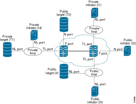
Table 13-6 lists the TL port translations supported in Cisco MDS 9000 Family switches. Figure 13-4 shows examples of TL port translation support.
Figure 13-4 TL Port Translation Support Examples
About TL Port ALPA Caches
Although TL ports cannot be automatically configured, you can manually configure entries in arbitrated loop physical address (ALPA) caches. Generally, ALPA cache entries are automatically populated when an ALPA is assigned to a device. Each device is identified by its port world wide name (pWWN). When a device is allocated an ALPA, an entry for that device is automatically created in the ALPA cache.
A cache contains entries for recently allocated ALPA values. These caches are maintained on various TL ports. If a device already has an ALPA, the Cisco SAN-OS software attempts to allocate the same ALPA to the device each time. The ALPA cache is maintained in persistent storage and saves information across switch reboots. The maximum cache size is 1000 entries. If the cache is full, and a new ALPA is allocated, the Cisco SAN-OS software discards an inactive cache entry (if available) to make space for the new entry. See the "TL Port" section for more information on TL ports.
Displaying TL Port Information
Private loop devices refer to legacy devices that reside on arbitrated loops. These devices are not aware of a switch fabric because they only communicate with devices on the same physical loop.
The legacy devices are used in Fibre Channel networks and devices outside the loop may need to communicate with them.The communication functionality is provided through TL ports.
Use the switchport mode command to configure a TL port (see the "Configuring Interface Modes" section).
The show tlport command displays the TL port interface configurations. This command provides a list of all TL ports configured in a switch and shows the associated VSAN, the FC ID for the port (only domain and area are valid), and the current operational state of the TL port (up or initializing). See Example 13-17 through Example 13-20.
Example 13-17 Displays the TL Ports in All VSANs
switch# show tlport list-------------------------------Interface Vsan FC-ID State------------------------- ------fc1/16 1 0x420000 Initfc2/26 1 0x150000 UpTL ports allow a private device (devices that physically reside on the loop) to see a fabric device and vice-versa by proxying fabric devices on the loop. Fabric devices are proxied by allocating each fabric device an ALPA on this loop.
In addition to these proxied devices, other virtual devices (local or remote domain controller addresses) are also allocated ALPAs on the loop. A switch reserves the ALPA for its own communication with private devices, and the switch acts as a SCSI initiator.
The first column in the output of the show tlport interface command is the ALPA identity of the device on the loop. The columns that follow include the port WWNs, the node WWNs for each device, the device as a SCSI initiator or target, and the real FC ID of the device.
Example 13-18 Displays the Detailed Information for a Specific TL Port
switch# show tlport interface fc1/16 allfc1/16 is up, vsan 1, FCID 0x420000-------------------------------------------------------------------------------- alpa pWWN nWWN SCSI Type Device FC-ID -------------------------------------------------------------------------------- 0x01 20:10:00:05:30:00:4a:de 20:00:00:05:30:00:4a:de Initiator Proxied 0xfffc42 0x73 22:00:00:20:37:39:ae:54 20:00:00:20:37:39:ae:54 Target Private 0x420073 0xef 20:10:00:05:30:00:4a:de 20:00:00:05:30:00:4a:de Initiator Switch 0x0000efExample 13-19 Displays TL Port Information for Private Devices
switch# show tlport interface fc 1/16 privatefc1/16 is up, vsan 1, FCID 0x420000------------------------------------------------------------------------alpa pWWN nWWN SCSI Type FC-ID ------------------------------------------------------------------------0x73 22:00:00:20:37:39:ae:54 20:00:00:20:37:39:ae:54 Target 0x4200730x74 22:00:00:20:37:38:d3:de 20:00:00:20:37:38:d3:de Target 0x420074Example 13-20 Displays TL Port Information for Proxied Devices
switch# show tlport interface fc 1/16 proxiedfc1/16 is up, vsan 1, FCID 0x420000------------------------------------------------------------------------alpa pWWN nWWN SCSI Type FC-ID ------------------------------------------------------------------------0x01 20:10:00:05:30:00:4a:de 20:00:00:05:30:00:4a:de Initiator 0xfffc420x02 21:00:00:e0:8b:01:95:e7 20:00:00:e0:8b:01:95:e7 Initiator 0x420100Manually Inserting Entries into ALPA Cache
To manually insert entries into the ALPA cache, follow these steps:
Displaying the ALPA Cache Contents
The show tlport alpa-cache command displays the contents of the ALPA cache.
switch# show tlport alpa-cache---------------------------------------------------------alpa pWWN Interface---------------------------------------------------------0x02 22:00:00:20:37:46:09:bd fc1/20x04 23:00:00:20:37:46:09:bd fc1/2The first entry indicates that if a device with a pWWN of 22:00:00:20:37:46:09:bd is exported on TL port fc1/2, then the pWWN is allocated an alpa 0x02 (if available).
Clearing the ALPA Cache
The clear tlport alpa-cache command clears the entire content of the ALPA cache.
Buffer Credits
Fibre Channel interfaces use buffer credits to ensure all packets are delivered to their destination. This section describes the different buffer credits available on the Cisco MDS Family switches and includes the following topics:
•
•
•
•
•
About Buffer-to-Buffer Credits
Buffer-to-buffer credits (BB_credits) are a flow control mechanism to ensure that FC switches do not run out of buffers, because switches must not drop frames. BB_credits are negotiated on a per-hop basis.
The receive BB_credit (fcrxbbcredit) value may be configured for each FC interface. In most cases, you do not need to modify the default configuration.
Note
•
•
•
Note
Configuring Buffer-to-Buffer Credits
To configure BB_credits for a Fibre Channel interface, follow these steps:
About Performance Buffers
Note
Regardless of the configured receive BB_credit value, additional buffers, called performance buffers, improve switch port performance. Instead of relying on the built-in switch algorithm, you can manually configure the performance buffer value for specific applications (for example, forwarding frames over FCIP interfaces).
For each physical Fibre Channel interface in any switch in the Cisco MDS 9000 Family, you can specify the amount of performance buffers allocated in addition to the configured receive BB_credit value.
The default performance buffer value is 0. If you use the default option, the built-in algorithm is used. If you do not specify this command, the default option is automatically used.
Configuring Performance Buffers
To configure performance buffers for a Fibre Channel interface, follow these steps:
Note
About Extended BB_credits
You can use the extended BB_credits flow control mechanism in addition to BB_credits for long haul links.
This section includes the following topics:
•
•
Extended BB_credits on Generation 1 Switching Modules
The BB_credits feature allows you to configure up to 255 receive buffers on Generation 1 switching modules. To facilitate BB_credits for long haul links, you can configure up to 3,500 receive BB_credits on a Fibre Channel port on a Generation 1 switching module.
To use this feature on Generation 1 switching modules, you must meet the following requirements:
•
•
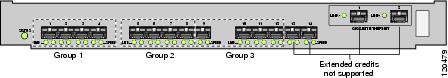
Figure 13-5 Port Group Support for the Extended BB_Credits Feature
The port groups that support extended credit configurations are as follows.
–
–
–
Note
•
•
–
Note
–
•
•
Note
Extended BB_credits on Generation 2 Switching Modules
To use this feature on Generation 2 switching modules, you must meet the following requirements:
•
•
Note
Configuring Extended BB_credits
To configure extended BB_credits for a MDS-14/2 interface, for a Generation 2 switching module interface (not including the Cisco MDS 9124 Fabric Switch), or for an interface in a Cisco MDS 9216i switch, follow these steps:
Displaying BB_Credit Information
To display the BB_credit information, use the show interface bbcredit command (see Example 13-21 and Example 13-22).
Example 13-21 Displays BB_credit Information
switch# show interface bbcreditfc2/1 is down (SFP not present)...fc2/17 is trunkingTransmit B2B Credit is 255Receive B2B Credit is 12Receive B2B Credit performance buffers is 37512 receive B2B credit remaining255 transmit B2B credit remainingfc2/18 is down (SFP not present)fc2/19 is down (SFP not present)fc2/20 is down (SFP not present)fc2/21 is down (Link failure or not-connected)...fc2/31 is upTransmit B2B Credit is 0Receive B2B Credit is 12Receive B2B Credit performance buffers is 4812 receive B2B credit remaining0 transmit B2B credit remainingfc2/32 is down (Link failure or not-connected)Example 13-22 Displays BB_credit Information for a Specified Fibre Channel Interface
switch# show interface fc2/31 bbcreditfc2/31 is upTransmit B2B Credit is 0Receive B2B Credit is 12Receive B2B Credit performance buffers is 4812 receive B2B credit remaining0 transmit B2B credit remainingManagement Interfaces
You can remotely configure the switch through the management interface (mgmt0). To configure a connection on the mgmt0 interface, you must configure either the IP version 4 (IPv4) parameters (IP address, subnet mask, and default gateway) or the IP version 6 (IPv6) parameters so that the switch is reachable.
This section describes the management interfaces and includes the following topics:
•
•
About Management Interfaces
Before you begin to configure the management interface manually, obtain the switch's IPv4 address and subnet mask, or the IPv6 address.
The management port (mgmt0) is autosensing and operates in full duplex mode at a speed of 10/100/1000 Mbps. Autosensing supports both the speed and the duplex mode. On a Supervisor-1 module, the default speed is 100 Mbps and the default duplex mode is auto. On a Supervisor-2 module, the default speed is auto and the default duplex mode is auto.
Note
Configuring Management Interfaces
To configure the mgmt0 Ethernet interface to connect over IPv4, follow these steps:
To configure the mgmt0 Ethernet interface to connect over IPv6, follow these steps:
Displaying Management Interface Configuration
To display the management interface configuration, use the show interface mgmt 0 command.
switch# show interface mgmt 0mgmt0 is upHardware is FastEthernetAddress is 000c.30d9.fdbcInternet address is 10.16.1.2/24MTU 1500 bytes, BW 100 Mbps full Duplex26388 packets input, 6101647 bytes0 multicast frames, 0 compressed0 input errors, 0 frame, 0 overrun 0 fifo10247 packets output, 2389196 bytes, 0 underruns0 output errors, 0 collisions, 0 fifo0 carrier errorsVSAN Interfaces
VSANs apply to Fibre Channel fabrics and enable you to configure multiple isolated SAN topologies within the same physical infrastructure. You can create an IP interface on top of a VSAN and then use this interface to send frames to this VSAN. To use this feature, you must configure the IP address for this VSAN. VSAN interfaces cannot be created for nonexisting VSANs.
This section describes VSAN interfaces and includes the following topics:
•
About VSAN Interfaces
Follow these guidelines when creating or deleting VSAN interfaces:
•
•
•
•
Tip
Creating VSAN Interfaces
To create a VSAN interface, follow these steps:
Displaying VSAN Interface Information
To display VSAN interface information, use the show interface vsan command.
switch# show interface vsan 2vsan2 is up, line protocol is upWWPN is 10:00:00:05:30:00:59:1f, FCID is 0xb90100Internet address is 10.1.1.1/24MTU 1500 bytes, BW 1000000 Kbit0 packets input, 0 bytes, 0 errors, 0 multicast0 packets output, 0 bytes, 0 errors, 0 droppedDefault Settings
Table 13-7 lists the default settings for interface parameters.