-
Cisco MDS 9000 Family CLI Configuration Guide, Release 3.3(3)
-
Index
-
New and Changed Information
-
Preface
- Getting Started
- Installation and Switch Management
- Switch Configuration
-
Fabric Configuration
-
Configuring and Managing VSANs
-
SAN Device Virtualization
-
Creating Dynamic VSANs
-
Configuring Inter-VSAN Routing
-
Distributing Device Alias Services
-
Configuring Fibre Channel Routing Services and Protocols
-
Managing FLOGI, Name Server, FDMI, and RSCN Databases
-
Discovering SCSI Targets
-
Configuring FICON
-
Advanced Features and Concepts
-
Configuring and Managing Zones
-
-
Security
-
Configuring FIPS
-
Configuring Users and Common Roles
-
Configuring SNMP
-
Configuring RADIUS and TACACS+
-
Configuring IPv4 and IPv6 Access Control Lists
-
Configuring Certificate Authorities and Digital Certificates
-
Configuring IPsec Network Security
-
Configuring FC-SP and DHCHAP
-
Configuring Port Security
-
Configuring Fabric Binding
-
- IP Services
- Intelligent Storage Services
- Network and Switch Monitoring
- Traffic Management
- Troubleshooting
-
Configuration Limits for Cisco MDS SAN-OS Release 3.x
-
 Feedback
Table Of Contents
Configuring IPv4 for Gigabit Ethernet Interfaces
Basic Gigabit Ethernet Configuration for IPv4
Configuring Interface Descriptions
Configuring the MTU Frame Size
Verifying Gigabit Ethernet Connectivity
About VLANs for Gigabit Ethernet
Configuring the VLAN Subinterface
Configuring Static IPv4 Routing
Displaying the IPv4 Route Table
Gigabit Ethernet IPv4-ACL Guidelines
Applying IPv4-ACLs on Gigabit Ethernet Interfaces
Configuring IPv4 for Gigabit Ethernet Interfaces
Cisco MDS 9000 Family supports IP version 4 (IPv4) on Gigabit Ethernet interfaces. This chapter describes how to configure IPv4 addresses and other IPv4 features.
This chapter includes the following topics:
•
Basic Gigabit Ethernet Configuration for IPv4
•
•
About IPv4
Both FCIP and iSCSI rely on TCP/IP for network connectivity. On each IPS module or MPS-14/2 module, connectivity is provided in the form of Gigabit Ethernet interfaces that are appropriately configured. This section covers the steps required to configure IP for subsequent use by FCIP and iSCSI.
Note
A new port mode, called IPS, is defined for Gigabit Ethernet ports on each IPS module or MPS-14/2 module. IP storage ports are implicitly set to IPS mode, so it can only be used to perform iSCSI and FCIP storage functions. IP storage ports do not bridge Ethernet frames or route other IP packets.
Each IPS port represents a single virtual Fibre Channel host in the Fibre Channel SAN. All the iSCSI hosts connected to this IPS port are merged and multiplexed through the single Fibre Channel host.
In large scale iSCSI deployments where the Fibre Channel storage subsystems do not require explicit LUN access control for every host device, use of proxy-initiator mode simplifies the configuration.
Note
Note
Tip
Basic Gigabit Ethernet Configuration for IPv4
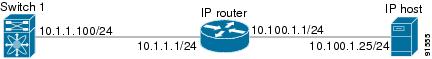
Figure 46-1 shows an example of a basic Gigabit Ethernet IP version 4 (IPv4) configuration.
Figure 46-1 Gigabit Ethernet IPv4 Configuration Example
Note
To configure the Gigabit Ethernet interface for the example in Figure 46-1, follow these steps:
This section includes the following topics:
•
•
Configuring Interface Descriptions
See the "About Interface Descriptions" section on page 13-15 for details on configuring the switch port description for any interface.
Configuring Beacon Mode
See the "About Beacon Mode" section on page 13-17 for details on configuring the beacon mode for any interface.
Configuring Autonegotiation
By default, autonegotiation is enabled all Gigabit Ethernet interface. You can enable or disable autonegotiation for a specified Gigabit Ethernet interface. When autonegotiation is enabled, the port automatically detects the speed or pause method, and duplex of incoming signals based on the link partner. You can also detect link up conditions using the autonegotiation feature.
To configure autonegotiation, follow these steps:
Configuring the MTU Frame Size
You can configure the interfaces on a switch to transfer large (or jumbo) frames on a port. The default IP maximum transmission unit (MTU) frame size is 1500 bytes for all Ethernet ports. By configuring jumbo frames on a port, the MTU size can be increased up to 9000 bytes.
Note
Tip
You do not need to explicitly issue the shutdown and no shutdown commands.
To configure the MTU frame size, follow these steps:
Configuring Promiscuous Mode
You can enable or disable promiscuous mode on a specific Gigabit Ethernet interface. By enabling the promiscuous mode, the Gigabit Ethernet interface receives all the packets and the software then filters and discards the packets that are not destined for that Gigabit Ethernet interface.
To configure the promiscuous mode, follow these steps:
Verifying Gigabit Ethernet Connectivity
Once the Gigabit Ethernet interfaces are connected with valid IP addresses, verify the interface connectivity on each switch. Ping the IP host using the IP address of the host to verify that the static IP route is configured correctly.
Note
- The IP address for the destination (IP host) is correctly configured.
- The host is active (powered on).
- The IP route is configured correctly.
- The IP host has a route to get to the Gigabit Ethernet interface subnet.
- The Gigabit Ethernet interface is in the up state.Use the ping command to verify the Gigabit Ethernet connectivity (see Example 46-1). The ping command sends echo request packets out to a remote device at an IP address that you specify (see the "Using the ping and ping ipv6 Commands" section on page 2-15).
Use the show interface gigabitethernet command to verify if the Gigabit Ethernet interface is up.
Example 46-1 Verifying Gigabit Ethernet Connectivity
switch# ping 10.100.1.25PING 10.100.1.25 (10.100.1.25): 56 data bytes64 bytes from 10.100.1.25: icmp_seq=0 ttl=255 time=0.1 ms64 bytes from 10.100.1.25: icmp_seq=1 ttl=255 time=0.1 ms64 bytes from 10.100.1.25: icmp_seq=2 ttl=255 time=0.1 ms--- 10.100.1.25 ping statistics ---3 packets transmitted, 3 packets received, 0% packet lossround-trip min/avg/max = 0.1/0.1/0.1 msVLANs
This section describes virtual LAN (VLAN) support in Cisco MDS SAN-OS and includes the following topics:
•
•
•
About VLANs for Gigabit Ethernet
Virtual LANs (VLANs) create multiple virtual Layer 2 networks over a physical LAN network. VLANs provide traffic isolation, security, and broadcast control.
Gigabit Ethernet ports automatically recognize Ethernet frames with IEEE 802.1Q VLAN encapsulation. If you need to have traffic from multiple VLANs terminated on one Gigabit Ethernet port, configure subinterfaces—one for each VLAN.
Note
- The Ethernet switch port connected to the IPS module or MPS-14/2 module is configured as a trunking port.
- The encapsulation is set to 802.1Q and not ISL, which is the default.Use the VLAN ID as a subscription to the Gigabit Ethernet interface name to create the subinterface name (the <slot-number>/<port-number>.<VLAN-ID>).
Configuring the VLAN Subinterface
To configure a VLAN subinterface (VLAN ID), follow these steps:
Interface Subnet Requirements
Gigabit Ethernet interfaces (major), subinterfaces (VLAN ID), and management interfaces (mgmt 0) can be configured in the same or different subnet depending on the configuration (see Table 46-1).
Note
Configuring Static IPv4 Routing
To configure static IPv4 routing (see Figure 46-1) through the Gigabit Ethernet interface, follow these steps:
Displaying the IPv4 Route Table
The ip route interface command takes the Gigabit Ethernet interface as a parameter and returns the route table for the interface. See Example 46-2.
Example 46-2 Displays the IP Route Table
switch# show ips ip route interface gig 8/1Codes: C - connected, S - staticNo default gatewayC 10.1.3.0/24 is directly connected, GigabitEthernet8/1Connected (C) identifies the subnet in which the interface is configured (directly connected to the interface). Static (S) identifies the static routes that go through the router.
IPv4-ACLs
This section describes the guidelines for IPv4 access control lists (IPv4-ACLs) and how to apply them to Gigabit Ethernet interfaces.
This section includes the following topics:
•
•
Note
Gigabit Ethernet IPv4-ACL Guidelines
Follow these guidelines when configuring IPv4-ACLs for Gigabit Ethernet interfaces:
•
Note
•
•
–
–
–
Tip
Applying IPv4-ACLs on Gigabit Ethernet Interfaces
To apply an IPv4-ACL on a Gigabit Ethernet interface, follow these steps:
ARP Cache
Cisco MDS SAN-OS supports ARP cache for Gigabit Ethernet interface configured for IPv4. This section includes the following topics:
Displaying ARP Cache
You can display the ARP cache on Gigabit Ethernet interfaces.
Note
Use the show ips arp interface gigabitethernet command to display the ARP cache on the Gigabit Ethernet interfaces. This command takes the Ethernet interface as a parameter and returns the ARP cache for that interface. See Example 46-3.
Example 46-3 Displays ARP Caches
switch# show ips arp interface gigabitethernet 7/1Protocol Address Age (min) Hardware Addr Type InterfaceInternet 20.1.1.5 3 0005.3000.9db6 ARPA GigabitEthernet7/1Internet 20.1.1.10 7 0004.76eb.2ff5 ARPA GigabitEthernet7/1Internet 20.1.1.11 16 0003.47ad.21c4 ARPA GigabitEthernet7/1Internet 20.1.1.12 6 0003.4723.c4a6 ARPA GigabitEthernet7/1Internet 20.1.1.13 13 0004.76f0.ef81 ARPA GigabitEthernet7/1Internet 20.1.1.14 0 0004.76e0.2f68 ARPA GigabitEthernet7/1Internet 20.1.1.15 6 0003.47b2.494b ARPA GigabitEthernet7/1Internet 20.1.1.17 2 0003.479a.b7a3 ARPA GigabitEthernet7/1...Clearing ARP Cache
The ARP cache can be cleared in two ways: clearing just one entry or clearing all entries in the ARP cache.
Use the clear ips arp command to clear the ARP cache. See Example 46-4 and Example 46-5.
Example 46-4 Clearing One ARP Cache Entry
switch# clear ips arp address 10.2.2.2 interface gigabitethernet 8/7arp clear successfulExample 46-5 Clearing All ARP Cache Entries
switch# clear ips arp interface gigabitethernet 8/7arp clear successfulDisplaying IPv4 Statistics
Use the show ips stats ip interface gigabitethernet to display and verify IP v4 statistics. This command takes the main Ethernet interface as a parameter and returns the IPv4 statistics for that interface. See Example 46-6.
Note
Example 46-6 Displays IPv4 Statistics
switch# show ips stats ip interface gigabitethernet 4/1Internet Protocol Statistics for port GigabitEthernet4/1168 total received, 168 good, 0 error0 reassembly required, 0 reassembled ok, 0 dropped after timeout371 packets sent, 0 outgoing dropped, 0 dropped no route0 fragments created, 0 cannot fragmentDefault Settings
Table 46-2 lists the default settings for IPv4 parameters.
Table 46-2 Default IPv4 Parameters
IPv4 MTU frame size
1500 bytes for all Ethernet ports.
Autonegotiation
Enabled.
Promiscuous mode
Disabled.