-
Cisco MDS 9000 Family Configuration Guide, Release 1.3 (from Release 1.3(1) through Release 1.3(6))
-
New and Changed Information
-
Index
-
Preface
-
Product Overview
-
Before You Begin
-
Obtaining and Installing Licenses
-
Initial Configuration
-
Configuring High Availability
-
Software Images
-
Managing Modules
-
Managing System Hardware
-
Configuring and Managing VSANs
-
Configuring Interfaces
-
Configuring Trunking
-
Configuring PortChannels\r\n
-
Configuring and Managing Zones
-
Configuring Inter-VSAN Routing
-
Managing FLOGI, Name Server, FDMI, and RSCN Databases
-
Configuring Switch Security
-
Configuring Fabric Security
-
Configuring Port Security
-
Configuring Fibre Channel Routing Services and Protocols
-
Configuring IP Services
-
Configuring FICON
-
Configuring IP Storage
-
Configuring Call Home
-
Configuring Domain Parameters
-
Configuring Traffic Management
-
Configuring System Message Logging
-
Discovering SCSI Targets
-
Monitoring Network Traffic Using SPAN
-
Advanced Features and Concepts
-
Configuring Fabric Configuration Servers
-
Monitoring System Processes and Logs
-
 Feedback
Table Of Contents
Starting a Switch in the Cisco MDS 9000 Family
Preparing to Configure the Switch
Configuring Out-of-Band Management
In-Band Management Configuration
Adjusting for Daylight Saving Time
Management Interface Configuration
Obtaining Remote Management Access
Configuring the Default Gateway
Working with Configuration Files
Displaying Configuration Files
Downloading Configuration Files to the Switch
From an External Flash (slot0:)
To an External CompactFlash Disk
Backing Up the Current Configuration
Rolling Back to a Previous Configuration
Restoring the Configured Redundancy Mode
Downgrading from a Higher Release
Verifying the Console Configuration
Verifying the COM1 Configuration
Guidelines to Configure Modems
Configuring the Initialization String
Configuring the Default Initialization String
Configuring a User-Specified Initialization String
Initializing a Modem in a Powered on Switch
Verifying the Modem Configuration
Displaying CDP Protocol Settings
Initial Configuration
This chapter describes how to initially configure switches so they can be accessed by other devices. This chapter includes the following sections:
•
Starting a Switch in the Cisco MDS 9000 Family
•
•
•
•
Starting a Switch in the Cisco MDS 9000 Family
The following procedure is a review of the tasks you should have completed during hardware installation, including starting up the switch. These tasks must be completed before you can configure the switch.
Before you can configure a switch, follow these steps:
Step 1
•
•
Refer to the Cisco MDS 9000 Family Hardware Installation Guide (for the required product) for more information.
Tip
Step 2
•
•
•
•
Step 3
Initial Setup Routine
The first time that you access a switch in the Cisco MDS 9000 Family, it runs a setup program that prompts you for the IP address and other configuration information necessary for the switch to communicate over the supervisor module Ethernet interface. This information is required to configure and manage the switch.
Note
Preparing to Configure the Switch
Before you configure a switch in the Cisco MDS 9000 Family for the first time, you need the following information:
•
–
–
•
•
•
•
•
•
–
–
•
•
•
•
Note
Default Login
All Cisco MDS 9000 Family switches have the network administrator as a default user (admin) and a default password (admin). You can change the default password, if required, during the initial setup process. You cannot change the default user at any time.
During the initial setup process, you have the option to configure one additional user in the network administrator role. If you change the administrator password during the initial setup process and subsequently forget this new password, you have the option to recover this password.
See the "Role-Based CLI Authorization" section for information on default roles and permissions and see the "Recovering Administrator Password" section for information on changing the administrator password.
Setup Options
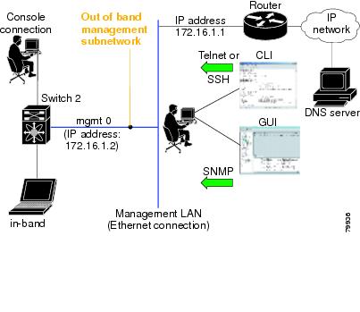
The setup scenario differs based on the subnet to which you are adding the new switch. You must configure a switch in the Cisco MDS 9000 Family with an IP address to enable management connections from outside of the switch.
Note
•
•
Figure 4-1 Management Access to Switches
Assigning Setup Information
This section describes how to initially configure the switch for both out-of-band and in-band management.
Note
Tip
Configuring Out-of-Band Management
Note
To configure the switch for first time out-of-band access, follow these steps:
Step 1
Step 2
This setup utility will guide you through the basic configuration ofthe system. Setup configures only enough connectivity for managementof the system.Press Enter incase you want to skip any dialog. Use ctrl-c at anytimeto skip away remaining dialogs.Would you like to enter the basic configuration dialog (yes/no): yesThe setup utility guides you through the basic configuration process. Press Ctrl-C at any prompt to end the configuration process.
Step 3
Enter the password for admin: adminStep 4
Create another login account (yes/no) [n]: yesWhile configuring your initial setup, you can create an additional user account (in the network-admin role) besides the administrator's account. See the "Role-Based CLI Authorization" section for information on default roles and permissions.
a.
Enter the user login ID: user_nameb.
Enter the password for user_name: user-passwordStep 5
Configure SNMPv3 Management parameters (yes/no) [y]: yesa.
SNMPv3 user name [admin]: adminb.
SNMPv3 user authentication password: admin_pass
Note
The admin password can have a minimum of one character, but the SNMP authentication password must have a minimum of eight characters.Step 6
Configure read-only SNMP community string (yes/no) [n]: yesa.
SNMP community string: snmp_communityStep 7
Note
Enter the switch name: switch_nameStep 8
Continue with Out-of-band (mgmt0) management configuration? [yes/no]: yesa.
Mgmt0 IP address: ip_addressb.
Mgmt0 IP netmask: subnet_maskStep 9
Continue with in-band (VSAN1) management configuration? (yes/no) [no]: noStep 10
Enable the ip routing capabilities? (yes/no) [y]: yesStep 11
Configure static route: (yes/no) [y]: yesa.
Destination prefix: dest_prefixb.
Destination prefix mask: dest_maskc.
Next hop ip address: next_hop_address
Note
Step 12
Configure the default-network: (yes/no) [y]: yesa.
Note
Default network IP address: dest_prefixStep 13
Configure the default-gateway: (yes/no) [y]: yesa.
IP address of the default-gateway: default_gatewayStep 14
Configure the DNS IP address? (yes/no) [y]: yesa.
DNS IP address: name_serverStep 15
Configure the default domain name? (yes/no) [n]: yesa.
Default domain name: domain_nameStep 16
Enable the telnet service? (yes/no) [y]: yesStep 17
Enabled SSH service? (yes/no) [n]: yesStep 18
Type the SSH key you would like to generate (dsa/rsa/rsa1)? dsaStep 19
Enter the number of key bits? (512 to 2048): 768Step 20
Configure NTP server? (yes/no) [n]: yesa.
NTP server IP address: ntp_server_IP_addressStep 21
Configure default switchport interface state (shut/noshut) [shut]: shut
Note
Step 22
Configure default switchport trunk mode (on/off/auto) [on]: onStep 23
Configure default zone policy (permit/deny) [deny]: denyDenies traffic flow to all members of the default zone.
Step 24
Enable full zoneset distribution (yes/no) [n]: noDisables the switch-wide default for the full-zoneset distribution feature.
Step 25
Enable FCID persistence in all the VSANs on this switch (yes/no) [n]: noDisables FC ID persistence in all VSANs in the switch.
You see the new configuration.
Step 26
Step 27
The following configuration will be applied:username admin password admin_pass role network-adminusername user_name password user_pass role network-adminsnmp-server user admin network-admin auth md5 admin_pass priv admin_passsnmp-server community snmp_community roswitchname switchinterface mgmt0ip address ip_address subnet_maskno shutdownip routingip route dest_prefix dest_mask dest_addressip default-network dest_prefixip default-gateway default_gatewayip name-server name_serverip domain-name domain_nametelnet server enablessh key dsa 768 forcessh server enablentp server ipaddr ntp_serverno system default switchport shutdownsystem default switchport trunk mode autono zone default-zone permit vsan 1-4093no zoneset distribute full vsan 1-4093no fcdomain fcid persistent global-enableWould you like to edit the configuration? (yes/no) [n]: noStep 28
Use this configuration and save it? (yes/no) [y]: yes
Caution
In-Band Management Configuration
The in-band management logical interface is VSAN 1. This management interface uses the Fibre Channel infrastructure to transport IP traffic. An interface for VSAN 1 is created on every switch in the fabric. Each switch should have its VSAN 1 interface configured with an IP address in the same subnetwork. A default route that points to the switch providing access to the IP network should be configured on every switch in the Fibre Channel fabric (see "Configuring and Managing VSANs").
Note
To configure a switch for first time in-band access, follow these steps:
Step 1
Step 2
---- Basic System Configuration Dialog ----This setup utility will guide you through the basic configuration ofthe system. Setup configures only enough connectivity for managementof the system.Press Enter incase you want to skip any dialog. Use ctrl-c at anytimeto skip away remaining dialogs.Would you like to enter the basic configuration dialog (yes/no): yesThe setup utility guides you through the basic configuration process. Press Ctrl-C from any prompt to end the configuration process.
Step 3
Enter the password for admin: new_passwordStep 4
Create another login account (yes/no) [no]: noStep 5
Configure SNMPv3 Management parameters (yes/no) [y]: yesa.
SNMPv3 user name [admin]: user_nameBy default, the SNMP user name is admin.
b.
SNMPv3 user authentication password [admin_pass]: admin_pass
Note
The admin password can have a minimum of one character, but the SNMP authentication password must have a minimum of eight characters.Step 6
a.
Configure read-only SNMP community string (yes/no) [n]: nob.
Configure read-only SNMP community string (yes/no) [n]: yesc.
SNMP community string: snmp_communityStep 7
Note
Enter the switch name: switch_nameStep 8
Continue with Out-of-band (mgmt0) management configuration? [yes/no]: noStep 9
Continue with in-band (VSAN1) management configuration? (yes/no) [no]: yesa.
VSAN1 IP address: ip_addressb.
VSAN1 IP net mask: subnet_maskStep 10
Enable ip routing capabilities? (yes/no) [y]: yesStep 11
Configure static route: (yes/no) [y]: noStep 12
Configure the default-network: (yes/no) [y]: noStep 13
Configure the default-gateway: (yes/no) [y]: yesa.
IP address of the default-gateway: default_gatewayStep 14
Configure the DNS IP address? (yes/no) [y]: noStep 15
Configure the default domain name? (yes/no) [n]: noStep 16
Enable the telnet service? (yes/no) [y]: noStep 17
Enabled SSH service? (yes/no) [n]: yesStep 18
Type the SSH key you would like to generate (dsa/rsa/rsa1)? rsaStep 19
Enter the number of key bits? (512 to 1024): 1024Step 20
Configure NTP server? (yes/no) [n]: noStep 21
Configure default switchport interface state (shut/noshut) [shut]: shut
Note
Step 22
Configure default switchport trunk mode (on/off/auto) [on]: onStep 23
Configure default zone policy (permit/deny) [deny]: denyDenies traffic flow to all members of the default zone.
Step 24
Enable full zoneset distribution (yes/no) [n]: noDisables the switch-wide default for the full-zoneset distribution feature.
Step 25
Enable FCID persistence in all the VSANs on this switch (yes/no) [n]: noDisables FC ID persistence in all VSANs in the switch.
You see the new configuration.
Step 26
Step 27
The following configuration will be applied:username admin password admin_pass role network-adminsnmp-server user snmp_user network-admin auth md5 snmp_pass priv snmp_passsnmp-server community snmp_community rwswitchname switchinterface vsan1ip address ip_address subnet_maskno shutdownip default-gateway default_gatewayno telnet server enablessh key rsa 1024 forcessh server enableno system default switchport shutdownsystem default switchport trunk mode autono zone default-zone permit vsan 1-4093no zoneset distribute full vsan 1-4093no fcdomain fcid persistent global-enableWould you like to edit the configuration? (yes/no) [n]: noStep 28
Use this configuration and save it? (yes/no) [y]: yes
Caution
Using the setup Command
To make changes to the initial configuration at a later time, you can issue the setup command in EXEC mode.
switch# setup---- Basic System Configuration Dialog ----This setup utility will guide you through the basic configuration ofthe system. Setup configures only enough connectivity for managementof the system.*Note: setup always assumes a predefined defaults irrespectiveof the current system configuration when invoked from CLI.Press Enter incase you want to skip any dialog. Use ctrl-c at anytimeto skip away remaining dialogs.Would you like to enter the basic configuration dialog (yes/no): yesThe setup utility guides you through the basic configuration process.
Accessing the Switch
After initial configuration, you can access the switch in one of three ways (see Figure 4-2):
•
•
Note
•
Figure 4-2 Switch Access Options
Assigning a Switch Name
Each switch in the fabric requires a unique name. You can assign names to easily identify the switch by its physical location, its SAN association, or the organization to which it is deployed. The assigned name is displayed in the command-line prompt. The switch name is limited to 32 alphanumeric characters.
Note
To change the name of the switch, follow these steps:
Where Do You Go Next?
After reviewing the default configuration, you can change it or perform other configuration or management tasks. The initial setup can only be performed at the CLI. However, you can continue to configure other software features, or access the switch after initial configuration by using either the CLI or the Device Manager and Fabric Manager applications.
To use the Cisco MDS 9000 Fabric Manager, refer to the Cisco MDS 9000 Family Fabric Manager Configuration Guide.
Verifying the Module Status
Before you begin configuring the switch, you need to ensure that the modules in the chassis are functioning as designed. To verify the status of a module at any time, issue the show module command in EXEC mode. A sample output of the show module command follows:
switch# show moduleMod Ports Module-Type Model Status--- ----- -------------------------------- ------------------ ------------1 0 Caching Services Module DS-X9560-SMAP ok2 8 IP Storage Services Module DS-X9308-SMIP ok <-------IPS-8 module4 16 2x1GE IPS, 14x1/2Gbps FC Module DS-X9216i-K9-SUP ok <-------MPS-14/2 module5 0 Supervisor/Fabric-1 DS-X9530-SF1-K9 active *6 0 Supervisor/Fabric-1 DS-X9530-SF1-K9 ha-standby9 4 IP Storage Services Module DS-X9304-SMIP ok <---------IPS-4 moduleMod Sw Hw World-Wide-Name(s) (WWN)--- ----------- ------ --------------------------------------------------1 2.0(1) 0.201 20:41:00:0b:fd:44:68:c0 to 20:48:00:0b:fd:44:68:c02 2.0(0.196) 0.206 20:41:00:0b:fd:44:68:c0 to 20:48:00:0b:fd:44:68:c04 2.0(1) 0.201 20:c1:00:05:30:00:07:1e to 20:d0:00:05:30:00:07:1e5 2.0(1) 0.0 --6 2.0(1) 0.0 --9 2.0(1) 0.1 22:01:00:05:30:00:07:1e to 22:04:00:05:30:00:07:1eMod Application Image Description Application Image Version-------- ----------------------------- -------------------------1 svc-node1 2.0(1)1 svc-node2 2.0(1)Mod MAC-Address(es) Serial-Num--- -------------------------------------- ----------1 00-05-30-01-49-c2 to 00-05-30-01-4a-46 JAB073907EP2 00-05-30-00-9d-d2 to 00-05-30-00-9d-de JAB064605a24 00-05-30-01-7f-32 to 00-05-30-01-7f-38 JAB081405AM5 00-05-30-00-2c-4e to 00-05-30-00-2c-52 JAB06350B1M6 00-05-30-00-19-66 to 00-05-30-00-19-6a JAB073705GL9 00-0d-bc-2f-d6-00 to 00-0d-bc-2f-d6-08 JAB080804TN* this terminal sessionIf the status is OK or active, you can continue with your configuration (see "Managing Modules").
Configuring Date and Time
Switches in the Cisco MDS 9000 Family use Universal Coordinated Time (UTC), which is the same as Greenwich Mean Time (GMT). To change the default time on the switch, issue the clock command from EXEC mode.
switch# clock set <HH:MM:SS> <DD> <Month in words> <YYYY>For example:
switch# clock set 15:58:09 23 September 2002Mon Sep 23 15:58:09 UTC 2002Where HH represents hours in military format (15 for 3 p.m.), MM is minutes (58), SS is seconds (09), DD is the date (23), Month is the month in words (September), and YYYY is the year (2002).
Note
Configuring the Time Zone
You can specify a time zone for the switch.
To specify the local time without the daylight savings feature, follow these steps:
Adjusting for Daylight Saving Time
Following U.S. standards, you can have the switch advance the clock one hour at 2:00 a.m. on the first Sunday in April and move back the clock one hour at 2:00 a.m. on the last Sunday in October. You can also explicitly specify the start and end dates and times and whether or not the time adjustment recurs every year.
To enable the daylight saving time clock adjustment according to the U.S. rules, follow these steps:
NTP Configuration
A Network Time Protocol (NTP) server provides a precise time source (radio clock or atomic clock) to synchronize the system clocks of network devices. NTP is transported over User Datagram Protocol UDP/IP. All NTP communications use UTC. An NTP server receives its time from a reference time source, such as a radio clock or atomic clock, attached to the time. NTP distributes this time across the network.
In a large enterprise network, having one time standard for all network devices is critical for management reporting and event logging functions when trying to correlate interacting events logged across multiple devices. Many enterprise customers with extremely mission-critical networks maintain their own stratum-1 NTP source.
Time synchronization happens when several frames are exchanged between clients and servers. The switches in client mode know the address of one or more NTP servers. The servers act as the time source and receive client synchronization requests.
By configuring an IP address as a peer, the switch will obtain and provide time as required. The peer is capable of providing time on its own and is capable of having a server configured. If both these instances point to different time servers, your NTP service is more reliable. Thus, even if the active server link is lost, you can still maintain the right time due to the presence of the peer.
Tip
If you only configure a peer, the most accurate peer takes on the role of the NTP server and the other peer(s) act as a peer(s). Both machines end at the right time if they have the right time source or if they point to the right NTP source.
Configuring NTP
To configure NTP in a server association, follow these steps:
NTP Configuration Guidelines
The following guidelines apply to all NTP configurations:
•
•
•
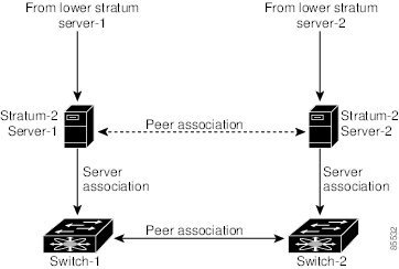
Not even a server down time will affect well-configured switches in the network. Figure 4-3 displays a network with two NTP stratum 2 servers and two switches.
Figure 4-3 NTP Peer and Server Association
In this configuration, the switches were configured as follows:
•
–
–
–
•
–
•
–
–
•
–
–
–
–
Management Interface Configuration
On director class switches, a single IP address is used to manage the switch. The active supervisor module's management (mgmt0) interface uses this IP address. The mgmt0 interface on the standby supervisor module remains in an inactive state and cannot be accessed until a switchover happens. After a switchover, the mgmt0 interface on the standby supervisor module becomes active and assumes the same IP address as the previously active supervisor module.
The management interface on the switch allows multiple simultaneous Telnet or SNMP sessions. You can remotely configure the switch through the management interface, but first you must configure some IP parameters (IP address, subnet mask) so that the switch is reachable. You can manually configure the management interface from the CLI.
The management port (mgmt0) is autosensing and operates in full duplex mode at a speed of 10/100 Mbps. The speed and mode cannot be configured.
Note
Obtaining Remote Management Access
In some cases, a switch interface might be administratively shut down. You can check the status of an interface at any time by using the show interface mgmt 0 command.
To obtain remote management access, follow these steps:
Using the force Option
When you try to shut down a management interface (mgmt0), a follow-up message confirms your action before performing the operation. You can use the force option to bypass this confirmation. The following example shuts down the interface without using the force option:
switch# config tswitch(config)# interface mgmt 0switch(config-if)# shutdownShutting down this interface will drop all telnet sessions.Do you wish to continue (y/n)? yThe following example shuts down the interface using the force option:
switch# config tswitch(config)# interface mgmt 0switch(config-if)# shutdown force
Note
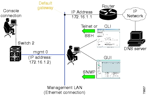
Default Gateway Configuration
The supervisor module sends IP packets with unresolved destination IP addresses to the default gateway (see Figure 4-4).
Figure 4-4 Default Gateway
Configuring the Default Gateway
To configure the IP address of the default gateway, follow these steps:
Step 1
Enters configuration mode.
Step 2
Configures the 172.16.1.1 IP address.
Telnet Server Connection
The Telnet server is enabled by default on all switches in the Cisco MDS 9000 Family. If you require a secure SSH connection, you need to disable the default Telnet connection and then enable the SSH connection (see the "Enabling SSH Service" section).
Note
Tip
Make sure the terminal is connected to the switch and that the switch and terminal are both powered on.
Disabling a Telnet Connection
To disable Telnet connections to the switch, follow these steps:
Working with Configuration Files
Configuration files can contain some or all of the commands needed to configure one or more switches. For example, you might want to download the same configuration file to several switches that have the same hardware configuration so that they have identical module and port configurations.
This section describes how to work with configuration files and has the following topics:
•
•
•
•
Displaying Configuration Files
Use the show running-config command to view the running configuration file.
switch# show running-configBuilding Configuration ...interface port-channel 98interface fc1/1interface fc1/2interface mgmt0ip address 172.22.95.112 255.255.255.0no shutdownvsan databasevsan 2clock summer-time Pacific 1 Sun Apr 02:00 5 Sun Oct 02:00 60switchname switch112Use the show startup-config command to view the startup configuration file.
switch# show startup-configinterface port-channel 98interface fc1/1channel-group 98 forceno shutdowninterface mgmt0ip address 172.22.95.112 255.255.255.0boot system system-237; ep-41boot kickstart boot-237 ep-41ip domain-name cisco.comDownloading Configuration Files to the Switch
You can configure a switch in the Cisco MDS 9000 Family by using configuration files you create or download from another switch. In addition, you can store configuration files on a bootflash device on the supervisor module and you can configure the switch using a configuration stored on an external CompactFlash disk.
Before you begin downloading a configuration file using a remote server, do the following:
•
•
•
Check connectivity to the remote server using the ping command.
From a Remote Server
To configure a switch in the Cisco MDS 9000 Family using a configuration file downloaded from a remote server using TFTP, FTP, SCP, or SFTP, follow these steps:
Step 1
Step 2
copy <scheme> :// <server address> system:running-config command, where scheme is TFTP, FTP, SCP, or SFTP.The configuration file downloads and the commands are executed as the file is parsed line by line.
Use the following command to download a configuration file from a remote server to the running configuration.
switch# copy <scheme>://<url> system:running-configFrom an External Flash (slot0:)
Note
To configure a switch in the Cisco MDS 9000 Family using a configuration file stored on an external CompactFlash disk, follow these steps:
Step 1
Step 2
Step 3
The commands are executed as the file is parsed line by line.
Use the following command to download a configuration file from an external CompactFlash to the running configuration:
switch copy slot0:dns-config.cfg system:running-configTo a Remote Server
To save a configuration file to a remote server such as TFTP, FTP, SCP, or SFTP, follow these steps:
Step 1
Step 2
Step 3
The configuration file is saved to the remote server.
Use the following command to save a running configuration file to a remote server:
switch# copy system:running-config <scheme>://<url>Use the following command to save a startup configuration file to a remote server:
switch# copy nvram:startup-config <scheme>://<url>To an External CompactFlash Disk
To save a configuration file on an external CompactFlash disk, follow these steps:
Step 1
Step 2
Step 3
The configuration file is saved to the CompactFlash disk.
Use the following command to save a running configuration file to an external CompactFlash disk:
switch# copy system:running-config slot0:dns-config.cfgUse the following command to save a startup configuration file to an external CompactFlash disk:
switch# copy nvram:startup-config slot0:dns-config.cfgSaving the Configuration
After you have created a configuration, you save the configuration using the following copy command:
switch# copy system:running-config nvram:startup-configThe copy running-config startup-config command is an alias to the previous command and is used frequently throughout this guide.
Copying Files
The syntax for the copy command follows and is explained in Table 4-1.
switch# copy <scheme>://<username@><server>/<file name>
<scheme>://<username@><server>/<file name>
Table 4-1 copy Command Syntax
bootflash
sup-active
sup-standby
sup-1 or module-5
sup-2 or module-6
sup-local
sup-remoteUser-specified
slot0
—
User-specified
volatile
—
User-specified
nvram
—
startup-config or snapshot-config
system
—
running-config
tftp1
IP address or DNS name
User-specified
ftp
scp (secure copy)
sftp
core
slot-number
Process identifier number
1 When downloading and uploading files, a TFTP limitation restricts a TFTP client to a 32 MB file size and some TFTP servers to a 16 MB file size.
•
switch# copy bootflash:system_image bootflash://sup-2/system_image•
switch# copy nvram:snapshot-config nvram:startup-config
Warning: this command is going to overwrite your current startup-config.
Do you wish to continue? {y/n} [y] y
•
switch# copy system:running-config bootflash:my-config•
switch# copy scp://user@10.1.7.2/system-image bootflash:system-image•
switch# copy sftp://172.16.10.100/myscript.txt volatile:myscript.txt
Note
Backing Up the Current Configuration
Before installing or migrating to any software configuration, back up the startup configuration.
•
switch# copy nvram:startup-config nvram:snapshot-config•
switch# copy nvram:startup-config bootflash:my-config•
switch# copy nvram:startup-config tftp://172.16.10.100/my-config•
switch# copy system:running-config bootflash:my-configRolling Back to a Previous Configuration
All switch configurations reside in the internal bootflash: file system. If your internal bootflash: file system is corrupted, you could potentially lose your configuration. Save and back up your configuration file periodically.
•
switch# copy nvram:snapshot-config nvram:startup-config
Note
•
switch# copy bootflash:my-config nvram:startup-config
Note
Restoring the Configured Redundancy Mode
Tip
By issuing the write erase command and the reload command, you restore the switch settings to their factory defaults. This sequence also restores the redundancy mode setting for the power supplies back to the redundant mode (default).
Depending on the type of power supply, the input voltage, and the number of modules (line cards) in the chassis, the redundancy mode may prevent the line cards from being powered on after a system reboot (see the "Configuring Power Supplies" section). If you use this sequence, the commands that apply to the powered down line cards will not be enforced on the switch (and will not be part of its running configuration).
If using the write erase and reload command sequence before rolling back to a saved configuration, follow these steps:
Step 1
Step 2
Step 3
Downgrading from a Higher Release
Use the install all command to gracefully reload the switch and handle configuration conversions. When downgrading any switch in the Cisco MDS 9000 Family, avoid using the reload command.
For example, to revert to Cisco MDS SAN-OS Release 1.0(4) or 1.0(3a) from Release 1.x, follow these steps:
Step 1
Step 2
Accessing Remote File Systems
To access contents of the standby supervisor module (remote), follow these steps:
Step 1
switch# dir bootflash://sup-remote12198912 Aug 27 17:21:10 2003 bootflash:boot-39a12198912 Aug 27 16:29:18 2003 bootflash:m9500-sf1ek9-kickstart-mzg.1.3.0.39a.bin1921922 Sep 14 19:58:12 2003 aOldImage1864931 Apr 29 12:41:50 2003 bOldImage1864931 Apr 29 12:41:59 2003 dplug212288 Apr 18 20:23:11 2003 lost+found/12097024 Nov 21 16:34:18 2003 m9500-sf1ek9-kickstart-mz.1.3.1.1.bin41574014 Nov 21 16:34:47 2003 m9500-sf1ek9-mz.1.3.1.1.bin1024 Oct 28 20:24:59 2003 newer-fs/2021518 Oct 11 15:49:41 2003 plugin-69aUsage for bootflash://sup-remote102081536 bytes used82478080 bytes free184559616 bytes totalStep 2
switch# del aOldImage
Deleting Files
Assuming you are already in the bootflash: directory, use the delete command as follows:
•
switch# delete dns_config.cfg•
switch# delete slot0:dns_config.cfg•
switch# delete slot0:test
Delete slot0:test? [confirm]
•
switch# delete bootflash:my-dirConfiguring Console Settings
A console port is an asynchronous serial port that enables switches in the Cisco MDS 9000 Family to be set up for initial configuration through a standard RS-232 port with an RJ-45 connector. Any device connected to this port must be capable of asynchronous transmission. Connection to a terminal requires a terminal emulator to be configured as 9600 baud, 8 data bits, 1 stop bit, no parity.
Caution
To configure the console port parameters from the console terminal, follow these steps:
Verifying the Console Configuration
Use the show line console command to verify the configured console settings. This command also displays problems that may have occurred along with the other registration statistics.
switch# show line consoleline Console:Speed: 9600 baudsDatabits: 8 bits per byteStopbits: 1 bit(s)Parity: noneModem In: EnableModem Init-String -default : ATE0Q1&D2&C1S0=1\015Statistics: tx:12842 rx:366 Register Bits:RTS|CTS|DTR|DSR|CD|RIConfiguring COM1 Settings
A COM1 port is a RS-232 port with a DB-9 interface that enables you to connect to an external serial communication device such as a modem. Connection to a terminal requires the terminal emulator to be configured as 9600 baud, 8 data bits, 1 stop bit, no parity.
To configure the COM1 port parameters, follow these steps:
Verifying the COM1 Configuration
Use the show line com1 command to verify the configured COM1 settings. This command also displays problems that may have occurred along with the other registration statistics.
switch# show line com1line Aux:Speed: 9600 baudsDatabits: 8 bits per byteStopbits: 1 bit(s)Parity: noneModem In: EnableModem Init-String -default : ATE0Q1&D2&C1S0=1\015Statistics: tx:17 rx:0 Register Bits:RTS|DTRConfiguring Modem Connections
Modems can only be configured if you are connected to the console or COM1 ports. A modem connection to a switch in the Cisco MDS 9000 Family does not affect switch functionality.
Note
Guidelines to Configure Modems
Tip
The following guidelines apply to modem configurations:
•
–
–
•
•
Follow the procedure specified in the "Initializing a Modem in a Powered on Switch" section.
Enabling Modem Connections
To configure a modem connection through the COM1 port, follow these steps:
To configure a modem connection through the console port, follow these steps:
Configuring the Initialization String
Switches in the Cisco MDS 9500 Family and the Cisco MDS 9216 switch have a default initialization string (ATE0Q1&D2&C1S0=1\015) to detect connected modems. The default string detects connected modems supported by Cisco Systems. The default string contents are as follows:
•
•
•
•
•
•
•
You may retain the default string or change it to another string (80 character limit) using the user-input option. This option is provided if you prefer to use a modem that is not supported or tested by Cisco systems. If you change the string, the changes you make are permanent and remain in effect unless you change them again. Rebooting the system or restarting the CLI does not change the modem initialization string. The switch is not affected even if the modem is not functioning.
Tip
The modem initialization string usage depends on the modem state when the switch boots:
•
•
Note
Configuring the Default Initialization String
To configure the default initialization string through the COM1 port, follow these steps:
To configure the default initialization string through the console port, follow these steps:
Configuring a User-Specified Initialization String
To configure a user-specified initialization string through the COM1 port, follow these steps:
To configure a user-specified initialization string through the console port, follow these steps:
Initializing a Modem in a Powered on Switch
When a switch is already powered on and the modem is later connected to either the console port or the COM1 port, you can initialize the modem using the modem connect line command in EXEC mode. You can specify the com1 option if the modem is connected to the COM1 port, or the console option if the modem is connected to the console.
To connect a modem to a switch that is already powered on, follow these steps.
Step 1
Step 2
Step 3
Verifying the Modem Configuration
Use the show line command to verify the configured modem settings.
switch# show lineline Console:Speed: 9600 baudsDatabits: 8 bits per byteStopbits: 1 bit(s)Parity: noneModem In: EnableModem Init-String -default : ATE0Q1&D2&C1S0=1\015Statistics: tx:12842 rx:366 Register Bits:RTS|CTS|DTR|DSR|CD|RIline Aux:Speed: 9600 baudsDatabits: 8 bits per byteStopbits: 1 bit(s)Parity: noneModem In: EnableModem Init-String -default : ATE0Q1&D2&C1S0=1\015Statistics: tx:17 rx:0 Register Bits:RTS|DTRCDP Configuration
The Cisco Discovery Protocol (CDP) is an advertisement protocol used by Cisco devices to advertise itself to other Cisco devices in the same network. CDP runs on the data link layer and is independent of Layer 3 protocols. Cisco devices that receive the CDP packets cache the information to make it is accessible through the CLI and SNMP.
CDP is supported on the management Ethernet interface on the supervisor module and the Gigabit Ethernet interface on the IPS module. The CDP daemon is restartable and switchable. The running and startup configurations are available across restarts and switchovers.
CDP version 1 (v1) and version 2 (v2) are supported in Cisco MDS 9000 Family switches. CDP packets with any other version number are silently discarded when received.
When the interface link is established, CDP is enabled by default and three CDP packets are sent at one-second intervals. Following this, the CDP frames are sent at the globally-configured refresh interval.
Configuring the CDP
To globally disable the CDP, follow these steps:
To disable the CDP protocol on a specific interface, follow these steps:
To globally configure the refresh time interval for the CDP protocol, follow these steps:
To globally configure the hold time advertised in CDP packets, follow these steps:
To globally configure the CDP version, follow these steps:
Clearing CDP Configurations
Use the clear cdp counters command to clear CDP traffic counters for all interfaces. You can issue this command for a specified interface or for all interfaces (management and Gigabit Ethernet interfaces).
switch# clear cdp countersswitch#Use the clear cdp table command to clear neighboring CDP entries for all interfaces. You can issue this command for a specified interface or for all interfaces (management and Gigabit Ethernet interfaces).
switch# clear cdp table interface gigabitethernet 4/1switch#Displaying CDP Protocol Settings
Use the show cdp command to display CDP entries. See Examples 4-1 to 4-11.
Example 4-1 Displays All CDP Capable Interfaces and Parameters
switch# show cdp allGigabitEthernet4/1 is upCDP enabled on interfaceSending CDP packets every 60 secondsHoldtime is 180 secondsGigabitEthernet4/8 is downCDP enabled on interfaceSending CDP packets every 60 secondsHoldtime is 180 secondsmgmt0 is upCDP enabled on interfaceSending CDP packets every 100 secondsHoldtime is 200 secondsExample 4-2 Displays All CDP Neighbor Entries
switch# show cdp entry all----------------------------------------Device ID:069038747(Kiowa3)Entry address(es):IP Address: 172.22.92.5Platform: WS-C5500, Capabilities: Trans-Bridge SwitchInterface: mgmt0, Port ID (outgoing port): 5/22Holdtime: 136 secVersion:WS-C5500 Software, Version McpSW: 2.4(3) NmpSW: 2.4(3)Copyright (c) 1995-1997 by Cisco SystemsAdvertisement Version: 1Example 4-3 Displays the Specified CDP Neighbor
switch# show cdp entry name 0----------------------------------------Device ID:0Entry address(es):IP Address: 0.0.0.0Platform: DS-X9530-SF1-K9, Capabilities: HostInterface: GigabitEthernet4/1, Port ID (outgoing port): GigabitEthernet4/1Holdtime: 144 secVersion:1.1(0.144)Advertisement Version: 2Duplex: fullExample 4-4 Displays Global CDP Parameters
switch# show cdp globalGlobal CDP information:CDP enabled globallySending CDP packets every 60 secondsSending a holdtime value of 180 secondsSending CDPv2 advertisements is enabledExample 4-5 Displays CDP Parameters for the Management Interface
switch# show cdp interface mgmt 0mgmt0 is upCDP enabled on interfaceSending CDP packets every 60 secondsHoldtime is 180 secondsExample 4-6 Displays CDP Parameters for the Gigabit Ethernet Interface
switch# show cdp interface gigabitethernet 4/1GigabitEthernet4/1 is upCDP enabled on interfaceSending CDP packets every 80 secondsHoldtime is 200 secondsExample 4-7 Displays CDP Neighbors (in brief)
switch# show cdp neighborsCapability Codes: R - Router, T - Trans-Bridge, B - Source-Route-BridgeS - Switch, H - Host, I - IGMP, r - RepeaterDevice ID Local Intrfce Hldtme Capability Platform Port ID0 Gig4/1 135 H DS-X9530-SF1- Gig4/1069038732(Kiowa2 mgmt0 132 T S WS-C5500 8/11069038747(Kiowa3 mgmt0 156 T S WS-C5500 6/20069038747(Kiowa3 mgmt0 158 T S WS-C5500 5/22Example 4-8 Displays CDP Neighbors (in detail)
switch# show CDP neighbor detail----------------------------------------Device ID:0Entry address(es):IP Address: 0.0.0.0Platform: DS-X9530-SF1-K9, Capabilities: HostInterface: GigabitEthernet4/1, Port ID (outgoing port): GigabitEthernet4/1Holdtime: 162 secVersion:1.1(0.144)Advertisement Version: 2Duplex: full----------------------------------------Device ID:069038732(Kiowa2)Entry address(es):IP Address: 172.22.91.5Platform: WS-C5500, Capabilities: Trans-Bridge SwitchInterface: mgmt0, Port ID (outgoing port): 8/11Holdtime: 132 secVersion:WS-C5500 Software, Version McpSW: 2.4(3) NmpSW: 2.4(3)Copyright (c) 1995-1997 by Cisco SystemsAdvertisement Version: 1Example 4-9 Displays the Specified CDP Neighbor (in detail)
switch# show CDP neighbors interface gigabitethernet 4/1 detail----------------------------------------Device ID:0Entry address(es):IP Address: 0.0.0.0Platform: DS-X9530-SF1-K9, Capabilities: HostInterface: GigabitEthernet4/1, Port ID (outgoing port): GigabitEthernet4/1Holdtime: 144 secVersion:1.1(0.144)Advertisement Version: 2Duplex: fullExample 4-10 Displays CDP Traffic Statistics for the Management Interface
switch# show cdp traffic interface mgmt 0----------------------------------------Traffic statistics for mgmt0Input Statistics:Total Packets: 1148Valid CDP Packets: 1148CDP v1 Packets: 1148CDP v2 Packets: 0Invalid CDP Packets: 0Unsupported Version: 0Checksum Errors: 0Malformed Packets: 0Output Statistics:Total Packets: 2329CDP v1 Packets: 1164CDP v2 Packets: 1165Send Errors: 0Example 4-11 Displays CDP Traffic Statistics for the Gigabit Ethernet Interface
switch# show cdp traffic interface gigabitethernet 4/1----------------------------------------Traffic statistics for GigabitEthernet4/1Input Statistics:Total Packets: 674Valid CDP Packets: 674CDP v1 Packets: 0CDP v2 Packets: 674Invalid CDP Packets: 0Unsupported Version: 0Checksum Errors: 0Malformed Packets: 0Output Statistics:Total Packets: 674CDP v1 Packets: 0CDP v2 Packets: 674Send Errors: 0