-
Cisco MDS 9000 Family Configuration Guide, Release 1.3 (from Release 1.3(1) through Release 1.3(6))
-
New and Changed Information
-
Index
-
Preface
-
Product Overview
-
Before You Begin
-
Obtaining and Installing Licenses
-
Initial Configuration
-
Configuring High Availability
-
Software Images
-
Managing Modules
-
Managing System Hardware
-
Configuring and Managing VSANs
-
Configuring Interfaces
-
Configuring Trunking
-
Configuring PortChannels\r\n
-
Configuring and Managing Zones
-
Configuring Inter-VSAN Routing
-
Managing FLOGI, Name Server, FDMI, and RSCN Databases
-
Configuring Switch Security
-
Configuring Fabric Security
-
Configuring Port Security
-
Configuring Fibre Channel Routing Services and Protocols
-
Configuring IP Services
-
Configuring FICON
-
Configuring IP Storage
-
Configuring Call Home
-
Configuring Domain Parameters
-
Configuring Traffic Management
-
Configuring System Message Logging
-
Discovering SCSI Targets
-
Monitoring Network Traffic Using SPAN
-
Advanced Features and Concepts
-
Configuring Fabric Configuration Servers
-
Monitoring System Processes and Logs
-
 Feedback
Table Of Contents
Configuring Gigabit Ethernet Interfaces
About Gigabit Ethernet Interfaces
Configuring a Basic Gigabit Ethernet Interface
Configuring the Interface Description
Configuring the Promiscuous Mode
About VLANs for Gigabit Ethernet
Configuring the VLAN Subinterface
Verifying Gigabit Ethernet Connectivity
Displaying Gigabit Ethernet Interface Statistics
Displaying Ethernet MAC Statistics
Displaying DMA-Bridge Statistics
Gigabit Ethernet High Availability
VRRP for iSCSI and FCIP Services
Configuring VRRP for Gigabit Ethernet Interfaces
Ethernet PortChannel Aggregation
Configuring Ethernet PortChannels
Advanced FCIP Profile Configuration
Configuring TCP Listener Ports
Advanced FCIP Interface Configuration
Configuring Active Connections
Configuring the Number of TCP Connections
Configuring FCIP Write Acceleration
Ethernet PortChannels and Fibre Channel PortChannels
Routing iSCSI Requests and Responses
Presenting Fibre Channel Targets as iSCSI Targets
iSCSI Virtual Target Configuration Examples
Presenting iSCSI Hosts as Virtual Fibre Channel Hosts
Making the Dynamic Initiator WWN Mapping Static
Assigning VSAN Membership to iSCSI Hosts
Assigning VSANs to a iSCSI Interface
Configuring iSCSI Proxy Initiators
Fibre Channel Zoning-Based Access Control
Displaying Proxy Initiator Information
Displaying Global iSCSI Information
Displaying iSCSI Virtual Targets
Displaying iSCSI User Information
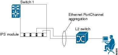
Multiple IPS Ports Connected to the Same IP Network
Ethernet PortChannel-Based High Availability
iSCSI Setup Guidelines and Scenarios
CHAP with Local Password Database
CHAP with External RADIUS Server
Configuring Storage Name Services
Creating iSNS Profiles and Tagging Profiles
Configuring IP Storage
Cisco MDS 9000 Family IP storage (IPS) services modules extend the reach of Fibre Channel SANs by using open-standard, IP-based technology. The switch connects separated SAN islands using Fibre Channel over IP (FCIP), and it allows IP hosts to access Fibre Channel storage using the iSCSI protocol.
This chapter includes the following sections:
•
Configuring Gigabit Ethernet Interfaces
•
•
Note
IP Storage Services Module
The IP Storage (IPS) services module (IPS module) allows you to use FCIP and iSCSI features. It integrates seamlessly into the Cisco MDS 9000 Family, and it supports the full range of features available on other switching modules, including VSANs, security, and traffic management.
The following types of IPS modules are currently available for use in any Cisco MDS 9216 switch or any switch in the Cisco MDS 9500 Series:
•
•
The Gigabit Ethernet ports in these module can be configured to support FCIP protocol, iSCSI protocol, or both protocols simultaneously.
•
Figure 22-1 FCIP Scenarios
•
Figure 22-2 iSCSI Scenarios
Verifying the Module Status
After inserting the module, verify the status of the module using the show module command:
switch# show moduleMod Ports Module-Type Model Status--- ----- ------------------------------- ------------------ ------------2 16 1/2 Gbps FC Module DS-X9016 ok3 4 IP Storage Services Module DS-X9304-SMIP ok <-------------IPS-4 module4 8 IP Storage Services Module DS-X9308-SMIP ok <-------------IPS-8 module5 0 Supervisor/Fabric-1 DS-X9530-SF1-K9 active *6 0 Supervisor/Fabric-1 DS-X9530-SF1-K9 ha-standbyMod Sw Hw World-Wide-Name(s) (WWN)--- ----------- ------ --------------------------------------------------2 1.1(1) 0.3 20:41:00:05:30:00:86:5e to 20:50:00:05:30:00:86:5e3 1.1(1) 0.2 20:01:00:05:30:00:86:5e to 20:c8:00:05:30:00:86:5e4 1.1(1) 0.2 20:c1:00:05:30:00:86:5e to 20:c8:00:05:30:00:86:5e5 1.1(1) 0.602 --6 1.1(1) 0.602 --Mod MAC-Address(es) Serial-Num--- -------------------------------------- ----------2 00-05-30-00-9f-62 to 00-05-30-00-9f-66 JAB064505YV3 00-05-30-00-ad-8e to 00-05-30-00-ad-9a JAB070806sd4 00-05-30-00-a1-ae to 00-05-30-00-a1-ba JAB0649059h5 00-05-30-00-9f-f6 to 00-05-30-00-9f-fa JAB06350B1M6 00-05-30-00-9f-f2 to 00-05-30-00-9f-f6 JAB06350B1F* this terminal sessionUpgrading IPS Modules
Caution
IPS modules use a rolling upgrade install mechanism whereby, each module in a given switch can only be upgraded in sequence. To guarantee a stable state, each IPS module in a switch requires a 5-minute delay before the next IPS module is upgraded.
Configuring Gigabit Ethernet Interfaces
This section includes the following topics:
•
•
•
•
•
•
•
About Gigabit Ethernet Interfaces
Both FCIP and iSCSI rely on TCP/IP for network connectivity. On each IPS module, connectivity is provided in the form of Gigabit Ethernet interfaces that are appropriately configured. This section covers the steps required to configure IP for subsequent use by FCIP and iSCSI.
A new port mode, called IPS, is defined for Gigabit Ethernet ports on each IPS module. IP storage ports are implicitly set to IPS mode, so it can only be used to perform iSCSI and FCIP storage functions. IP storage ports do not bridge Ethernet frames or route other IP packets.
Tip
Configuring a Basic Gigabit Ethernet Interface
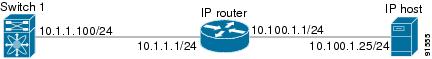
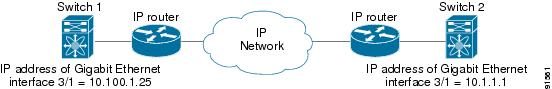
Figure 22-3 depicts a basic Gigabit Ethernet configuration.
Figure 22-3 Gigabit Ethernet Configuration
To configure the Gigabit Ethernet interface for the scenario in Figure 22-3, follow these steps:
Configuring the Interface Description
Refer to the "Configuring Interface Descriptions" section for details on configuring the switchport description for any interface.
Configuring the Beacon Mode
Refer to the "Configuring the Beacon Mode" section for details on configuring the beacon mode for any interface.
Configuring Auto-Negotiation
By default, the port is configured to auto-negotiate. You can configure auto-negotiation for a specified Gigabit Ethernet interface. By configuring auto-negotiation, the port automatically detects the speed or pause method, and duplex of incoming signals based on the link partner. You can also detect link up conditions using the auto-negotiation feature.
To configure auto-negotiation, follow these steps:
Configuring MTU Size
You can configure the switch to receive and transfer large (or jumbo) frames on a port. The default IP MTU frame size is 1500 bytes for all Ethernet ports. By configuring jumbo frames on a port, the MTU size can be increased to 9000 bytes. The following example sets the size to 3000 bytes. Independent of the MTU size, the IPS module does not pack multiple IP frames (converted to FCIP or to iSCSI).
Note
Tip
To configure MTU frame size, follow these steps:
Configuring the Promiscuous Mode
You can configure the promiscuous-mode to be on or off for a specified Gigabit Ethernet interface. By configuring the promiscuous mode all packets are received by the Gigabit Ethernet interface, the software then filters and discards the packets that are not destined for that Gigabit Ethernet interface.
To configure the promiscuous mode, follow these steps:
About VLANs for Gigabit Ethernet
Virtual LANs (VLANs) create multiple virtual Layer 2 networks over a physical LAN network. VLANs provide traffic isolation, security, and broadcast control.
IPS Gigabit Ethernet ports automatically recognize Ethernet frames with IEEE 802.1Q VLAN encapsulation. If you need to have traffic from multiple VLANs terminated on one IPS port, configure subinterfaces—one for each VLAN.
Note
- The Ethernet switch port connected to the IPS module is configured as a trunking port.
- The encapsulation is set to 802.1Q and not ISL, which is the default.Use the VLAN ID as a subscription to the Gigabit Ethernet interface name to create the subinterface name (the slot-number>/<port-number>.<VLAN-ID>).
Configuring the VLAN Subinterface
To configure a VLAN subinterface (the VLAN ID), follow these steps:
Interface Subnet Requirements
Gigabit Ethernet interfaces (major), subinterfaces (VLAN ID), and management interfaces (mgmt 0) can be configured in the same or different subnet depending on the configuration (see Table 22-1).
Note
Managing IP Routing
To configure static IP routing (see Figure 22-3) through the Gigabit Ethernet interface, follow these steps:
Displaying the IP Route Table
The show ips ip route interface ethernet command takes the ethernet interface as a parameter and returns the route table for the interface. See Example 22-1.
Example 22-1 Displays the Route Table
switch# show ips ip route interface gig 8/1Codes: C - connected, S - staticNo default gatewayC 10.1.3.0/24 is directly connected, GigabitEthernet8/1Connected (C) identifies the subnet in which the interface is configured (directly connected to the interface). Static (S) identifies the static routes that go through the router.
Verifying Gigabit Ethernet Connectivity
The ping command sends echo request packets out to a remote device at an IP address that you specify (see the "Using the ping Command" section).
Once the Gigabit Ethernet interfaces are connected with valid IP addresses, verify the interface connectivity on each switch using the ping command. Ping the IP host using the IP address of the host to verify that the static IP route is configured correctly. See Example 22-2.
Example 22-2 Verifying Gigabit Ethernet Connectivity
switch# ping 10.100.1.25PING 10.100.1.25 (10.100.1.25): 56 data bytes64 bytes from 10.100.1.25: icmp_seq=0 ttl=255 time=0.1 ms64 bytes from 10.100.1.25: icmp_seq=1 ttl=255 time=0.1 ms64 bytes from 10.100.1.25: icmp_seq=2 ttl=255 time=0.1 ms--- 10.100.1.25 ping statistics ---3 packets transmitted, 3 packets received, 0% packet lossround-trip min/avg/max = 0.1/0.1/0.1 ms
Note
- The IP address for the destination (IP host) is correctly configured.
- The host is active (powered on).
- The IP route is configured correctly.
- The IP host has a route to get to the Gigabit Ethernet interface subnet.
- The Gigabit Ethernet interface is in the up state (use the show interface gigabitethernet command).
Managing ARP Caches
Use the show ips arp interface gigabitethernet command to display the ARP cache on the Gigabit Ethernet interfaces. This command takes the Ethernet interface as a parameter and returns the ARP cache for that interface. See Example 22-3.
Example 22-3 Displays ARP Caches
switch# show ips arp interface gigabitethernet 7/1Protocol Address Age (min) Hardware Addr Type InterfaceInternet 20.1.1.5 3 0005.3000.9db6 ARPA GigabitEthernet7/1Internet 20.1.1.10 7 0004.76eb.2ff5 ARPA GigabitEthernet7/1Internet 20.1.1.11 16 0003.47ad.21c4 ARPA GigabitEthernet7/1Internet 20.1.1.12 6 0003.4723.c4a6 ARPA GigabitEthernet7/1Internet 20.1.1.13 13 0004.76f0.ef81 ARPA GigabitEthernet7/1Internet 20.1.1.14 0 0004.76e0.2f68 ARPA GigabitEthernet7/1Internet 20.1.1.15 6 0003.47b2.494b ARPA GigabitEthernet7/1Internet 20.1.1.17 2 0003.479a.b7a3 ARPA GigabitEthernet7/1...The ARP cache can be cleared in two ways: clearing just one entry or clearing all entries in the ARP cache. See Examples 22-4 and 22-5.
Example 22-4 Clearing One ARP Cache Entry
switch# clear ips arp address 10.2.2.2 interface gigabitethernet 8/7arp clear successfulExample 22-5 Clearing All ARP Cache Entries
switch# clear ips arp interface gigabitethernet 8/7arp clear successful
Note
Displaying Statistics
This section provides examples to verify Gigabit Ethernet and TCP/IP statistics on the IP storage ports.
Displaying Gigabit Ethernet Interface Statistics
Use the show interface Gigabit Ethernet command on each switch to verify that the interfaces are up and functioning as desired. See Example 22-6.
Example 22-6 Displays the Gigabit Ethernet Interface
switch# show interface gigabitethernet 8/1GigabitEthernet8/1 is up <-----------The interface is in the up state.Hardware is GigabitEthernet, address is 0005.3000.a98eInternet address is 10.1.3.1/24MTU 1500 bytes, BW 1000000 KbitPort mode is IPSSpeed is 1 GbpsBeacon is turned off5 minutes input rate 744 bits/sec, 93 bytes/sec, 1 frames/sec5 minutes output rate 0 bits/sec, 0 bytes/sec, 0 frames/sec3343 packets input, 406582 bytes0 multicast frames, 0 compressed0 input errors, 0 frame, 0 overrun 0 fifo8 packets output, 336 bytes, 0 underruns0 output errors, 0 collisions, 0 fifo0 carrier errorsExample 22-7 Displays the Gigabit Ethernet Subinterface
switch# show interface gigabitethernet 4/2.100GigabitEthernet4/2.100 is upHardware is GigabitEthernet, address is 0005.3000.abcbInternet address is 10.1.2.100/24MTU 1500 bytes5 minutes input rate 0 bits/sec, 0 bytes/sec, 0 frames/sec5 minutes output rate 0 bits/sec, 0 bytes/sec, 0 frames/sec0 packets input, 0 bytes0 multicast frames, 0 compressed0 input errors, 0 frame, 0 overrun 0 fifo1 packets output, 46 bytes, 0 underruns0 output errors, 0 collisions, 0 fifo0 carrier errorsDisplaying Ethernet MAC Statistics
The show ips stats mac interface gigabitethernet command takes the main Gigabit Ethernet interface as a parameter and returns Ethernet statistics for that interface. See Example 22-8.
Example 22-8 Displays Ethernet MAC Statistics
switch# show ips stats mac interface gigabitethernet 8/1Ethernet MAC statistics for port GigabitEthernet8/1Hardware Transmit Counters237 frame 43564 bytes0 collisions, 0 late collisions, 0 excess collisions0 bad frames, 0 FCS error, 0 abort, 0 runt, 0 oversizeHardware Receive Counters427916 bytes, 3464 frames, 0 multicasts, 3275 broadcasts0 bad, 0 runt, 0 CRC error, 0 length error0 code error, 0 align error, 0 oversize errorSoftware Counters3429 received frames, 237 transmit frames0 frames soft queued, 0 current queue, 0 max queue0 dropped, 0 low memory
Note
Displaying DMA-Bridge Statistics
You can display direct memory access (DMA) device statistics using the show ips stats dma-bridge interface gigabitethernet command. This command takes the main Gigabit Ethernet interface as a parameter and returns Ethernet statistics for that interface. See Example 22-9.
Example 22-9 Displays DMA-Bridge Statistics
switch# show ips stats dma-bridge interface gigabitethernet 7/1Dma-bridge ASIC Statistics for port GigabitEthernet7/1Hardware Egress Counters231117 Good, 0 bad protocol, 0 bad header cksum, 0 bad FC CRCHardware Ingress Counters218255 Good, 0 protocol error, 0 header checksum error0 FC CRC error, 0 iSCSI CRC error, 0 parity errorSoftware Egress Counters231117 good frames, 0 bad header cksum, 0 bad FIFO SOP0 parity error, 0 FC CRC error, 0 timestamp expired error0 unregistered port index, 0 unknown internal type0 RDL ok, 0 RDL drop (too big), 0 RDL ttl_13656368645 idle poll count, 0 loopback, 0 FCC PQ, 0 FCC EQFlow Control: 0 [0], 0 [1], 0 [2], 0 [3]Software Ingress Counters218255 Good frames, 0 header cksum error, 0 FC CRC error0 iSCSI CRC error, 0 descriptor SOP error, 0 parity error0 frames soft queued, 0 current Q, 0 max Q, 0 low memory0 out of memory drop, 0 queue full drop0 RDL ok, 0 RDL drop (too big)Flow Control: 0 [0], 0 [1], 0 [2], 0 [3]This output shows all Fibre Channel frames that ingress or egress from the Gigabit Ethernet port.
Note
Displaying TCP/IP Statistics
Note
Use the show ips stats ip interface gigabitethernet to display and verify IP statistics. This command takes the main Gigabit Ethernet interface as a parameter and returns IP statistics for that interface. See Example 22-10.
Example 22-10 Displays IP Statistics
switch# show ips stats ip interface gigabitethernet 4/1Internet Protocol Statistics for port GigabitEthernet4/1168 total received, 168 good, 0 error0 reassembly required, 0 reassembled ok, 0 dropped after timeout371 packets sent, 0 outgoing dropped, 0 dropped no route0 fragments created, 0 cannot fragmentUse the show ips stats tcp interface gigabitethernet to display and verify TCP statistics. This command takes the main Ethernet interface as a parameter, and shows TCP stats along with the connection list and TCP state. The detail option shows all information maintained by the interface. See Examples 22-11 and 22-12.
Example 22-11 Displays TCP Statistics
switch# show ips stats tcp interface gigabitethernet 4/1TCP Statistics for port GigabitEthernet4/1Connection Stats0 active openings, 3 accepts0 failed attempts, 12 reset received, 3 establishedSegment stats163 received, 355 sent, 0 retransmitted0 bad segments received, 0 reset sentTCP Active ConnectionsLocal Address Remote Address State Send-Q Recv-Q0.0.0.0:3260 0.0.0.0:0 LISTEN 0 0Example 22-12 Displays Detailed TCP Statistics
switch# show ips stats tcp interface gigabitethernet 4/1 detailTCP Statistics for port GigabitEthernet4/1TCP send stats355 segments, 37760 bytes222 data, 130 ack only packets3 control (SYN/FIN/RST), 0 probes, 0 window updates0 segments retransmitted, 0 bytes0 retransmitted while on ethernet send queue, 0 packets split0 delayed acks sentTCP receive stats163 segments, 114 data packets in sequence, 6512 bytes in sequence0 predicted ack, 10 predicted data0 bad checksum, 0 multi/broadcast, 0 bad offset0 no memory drops, 0 short segments0 duplicate bytes, 0 duplicate packets0 partial duplicate bytes, 0 partial duplicate packets0 out-of-order bytes, 1 out-of-order packets0 packet after window, 0 bytes after window0 packets after close121 acks, 37764 ack bytes, 0 ack toomuch, 4 duplicate acks0 ack packets left of snd_una, 0 non-4 byte aligned packets8 window updates, 0 window probe30 pcb hash miss, 0 no port, 0 bad SYN, 0 paws dropsTCP Connection Stats0 attempts, 3 accepts, 3 established3 closed, 2 drops, 0 conn drops0 drop in retransmit timeout, 1 drop in keepalive timeout0 drop in persist drops, 0 connections drainedTCP Miscellaneous Stats115 segments timed, 121 rtt updated0 retransmit timeout, 0 persist timeout12 keepalive timeout, 11 keepalive probesTCP SACK Stats0 recovery episodes, 0 data packets, 0 data bytes0 data packets retransmitted, 0 data bytes retransmitted0 connections closed, 0 retransmit timeoutsTCP SYN Cache Stats15 entries, 3 connections completed, 0 entries timed out0 dropped due to overflow, 12 dropped due to RST0 dropped due to ICMP unreach, 0 dropped due to bucket overflow0 abort due to no memory, 0 duplicate SYN, 0 no-route SYN drop0 hash collisions, 0 retransmittedTCP Active ConnectionsLocal Address Remote Address State Send-Q Recv-Q0.0.0.0:3260 0.0.0.0:0 LISTEN 0 0Use the show ips stats icmp interface gigabitethernet to display and verify IP statistics. This command takes the main Ethernet interface as a parameter and returns the ICMP statistics for that interface. See Example 22-13.
Example 22-13 Displays ICMP Statistics
switch# show ips stats icmp interface gigabitethernet 4/1ICMP Statistics for port GigabitEthernet4/15 ICMP messages received0 ICMP messages dropped due to errorsICMP input histogram5 echo requestICMP output histogram5 echo replyGigabit Ethernet High Availability
Virtual Router Redundancy Protocol (VRRP) and Ethernet PortChannels are two Gigabit Ethernet features that provide high availability for iSCSI and FCIP services.
VRRP for iSCSI and FCIP Services
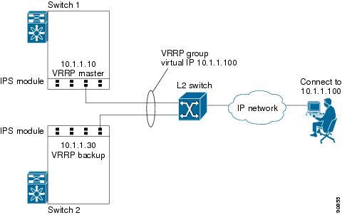
VRRP provides a redundant alternate path to the Gigabit Ethernet port for iSCSI and FCIP services. VRRP provides IP address fail over protection to an alternate Gigabit Ethernet interface so the IP address is always available (see Figure 22-4).
Figure 22-4 VRRP Scenario
In Figure 22-4, all members of the VRRP group must be IP storage Gigabit Ethernet ports. VRRP group members can be one or more of the following interfaces:
•
•
•
•
•
•
See the "Configuring VRRP" section.
Configuring VRRP for Gigabit Ethernet Interfaces
Note
To configure VRRP for Gigabit Ethernet interfaces, follow these steps:
Ethernet PortChannel Aggregation
Ethernet PortChannels refer to the aggregation of multiple physical Gigabit Ethernet interfaces into one logical Ethernet interface to provide link redundancy and, in some cases, higher aggregated bandwidth and load balancing.
The data traffic from one TCP connection always travels on the same physical links. An Ethernet switch connecting to the MDS Gigabit Ethernet port can implement load balancing based on the IP address, IP address and UDP/TCP port number, or MAC address.
Note
Ethernet PortChannels can only aggregate two physical interfaces that are adjacent to each other on a given IPS module (see Figure 22-5).
Note
Figure 22-5 Ethernet PortChannel Scenario
In Figure 22-5, Gigabit Ethernet ports 3 and 4 in slot 9 are aggregated into an Ethernet PortChannel.
Note
Note
Configuring Ethernet PortChannels
Note
- The interface already has an IP address assigned.
- The subinterfaces are configured on that interface.The PortChannel configuration specified in "Configuring PortChannels" also applies to Ethernet PortChannel configurations.
To configure Ethernet PortChannels, follow these steps:
Configuring CDP
The Cisco Discovery Protocol (CDP) is supported on the management Ethernet interface on the supervisor module and the Gigabit Ethernet interface on the IPS module.
See the "CDP Configuration" section.
IPS Core Dumps
IPS core dumps are different from the system's kernel core dumps for other modules. When the IPS module's operating system (OS) unexpectedly resets, it is sometimes useful to obtain a copy of the memory image (called a IPS core dump) to identify the cause of the reset. Under that condition, the IPS module sends the core dump to the supervisor module for storage. Core dumps take up significant space and hence the level of what gets stored can be configured using one of the following options:
•
•
Configuring IPS Core Dumps
To configure IPS core dumps on the IPS module, follow these steps:
Configuring FCIP
This section includes the following topics:
•
•
•
About FCIP
The Fibre Channel over IP Protocol (FCIP) is a tunneling protocol that connects geographically distributed Fibre Channel storage area networks (SAN islands) transparently over IP local area networks (LANs), metropolitan area networks (MANs), and wide area networks (WANs). See Figure 22-6.
Figure 22-6 Fibre Channel SANs Connected by FCIP
FCIP uses TCP as a network layer transport.
Note
To configure the IPS module for FCIP, you should have a basic understanding of the following concepts:
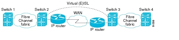
FCIP and VE Ports
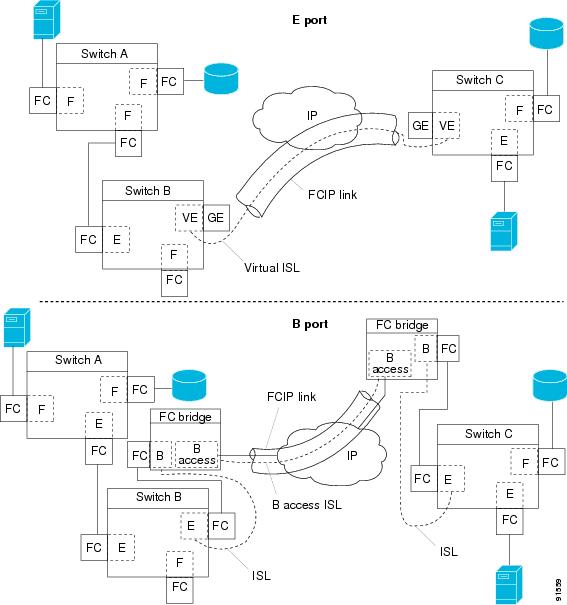
Figure 22-7 describes the internal model of FCIP with respect to Fibre Channel Inter-Switch Links (ISLs) and Cisco's enhanced ISLs (EISLs).
FCIP virtual E (VE) ports behave exactly like standard Fibre Channel E ports, except that the transport in this case is FCIP instead of Fibre Channel. The only requirement is for the other end of the VE port to be another VE port.
A virtual ISL is established over a FCIP link and transports Fibre Channel traffic. Each associated virtual ISL looks like a Fibre Channel ISL with either an E port or a TE port at each end (see Figure 22-7).
Figure 22-7 FCIP Links and Virtual ISLs
See the "E Port" section.
FCIP Links
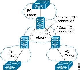
FCIP links consist of one or more TCP connections between two FCIP link endpoints. Each link carries encapsulated Fibre Channel frames.
When the FCIP link comes up, the VE ports at both ends of the FCIP link create a virtual Fibre Channel (E)ISL and initiate the E port protocol to bring up the (E)ISL.
By default, the FCIP feature on any Cisco MDS 9000 Family switch creates two TCP connections for each FCIP link.
•
•
To enable FCIP on the IPS module, a FCIP profile and FCIP interface (interface FCIP) must be configured.
The FCIP link is established between two peers, the VE port initialization behavior is identical to a normal E port. This behavior is independent of the link being FCIP or pure Fibre Channel, and is based on the E port discovery process (ELP, ESC).
Once the FCIP link is established, the VE port behavior is identical to E port behavior for all inter-switch communication (including domain management, zones, and VSANs). At the Fibre Channel layer, all VE and E port operations are identical.
FCIP Profiles
The FCIP profile contains information about local IP address and TCP parameters. The profile defines the following information:
•
•
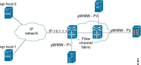
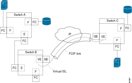
The FCIP profile's local IP address determines the Gigabit Ethernet port where the FCIP links terminate (see Figure 22-8).
Figure 22-8 FCIP Profile and FCIP Links
FCIP Interfaces
The FCIP interface is the local endpoints of the FCIP link and a VE port interface. All the FCIP and E port parameters are configured in context to the FCIP interface.
The FCIP parameters consist of the following:
•
•
•
•
Enabling FCIP
To begin configuring the FCIP feature, you must explicitly enable FCIP on the required switches in the fabric. By default, this feature is disabled in all switches in the Cisco MDS 9000 Family.
The configuration and verification commands for the FCIP feature are only available when FCIP is enabled on a switch. When you disable this feature, all related configurations are automatically discarded.
To enable FCIP on any participating switch, follow these steps:
Basic FCIP Configuration
To configure a FCIP link, follow these steps on both switches:
Step 1
Step 2
Step 3
Step 4
Step 5
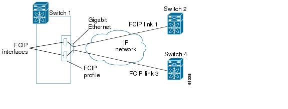
Creating FCIP Profiles
You must assign a local IP address of a Gigabit Ethernet interface or subinterface to the FCIP profile to create a FCIP profile (see Figure 22-9).
Figure 22-9 Assigning Profiles to Each Gigabit Ethernet Interface
To create a FCIP profile in switch 1, follow these steps:
To assign FCIP profile in switch 2, follow these steps:
Creating FCIP Links
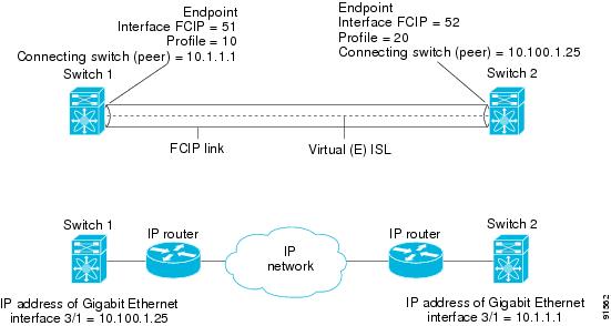
When two FCIP link endpoints are created, a FCIP link is established between the two IPS modules. To create a FCIP link, assign a profile to the FCIP interface and configure the peer information. The peer IP switch information initiates (creates) a FCIP link to that peer switch (see Figure 22-10).
Figure 22-10 Assigning Profiles to Each Gigabit Ethernet Interface
To create a FCIP link endpoints in switch 1, follow these steps:
To create a FCIP link endpoints in switch 2, follow these steps:
Advanced FCIP Profile Configuration
A basic FCIP configuration uses the local IP address to configure the FCIP profile. In addition to the local IP address and the local port, you can specify other TCP parameters as part of the FCIP profile configuration.
•
FCIP configuration options can be accessed from the switch(config-profile)# submode prompt.
To enter the switch(config-profile)# prompt, follow these steps:
Configuring TCP Listener Ports
The default TCP port for FCIP is 3225.
You can change this port using the port command.
To change the default FCIP port number (3225), follow these steps:
Step 1
Associates the profile with the local port number (5000).
Reverts to the default 3225 port.
Configuring TCP Parameters
You can control TCP behavior in a switch by configuring the following TCP parameters.
•
Minimum Retransmit Timeout
You can control the minimum amount of time TCP waits before retransmitting. By default, this value is 200 milliseconds (ms).
To configure the minimum retransmit time, follow these steps:
Keepalive Timeout
You can configure the interval that the TCP connection uses to verify that the FCIP link is functioning. This ensures that a FCIP link failure is detected quickly even when there is no traffic.
If the TCP connection is idle for more than the specified time, then keepalive timeout packets are sent to ensure that the connection is active. This command can be used to tune the time taken to detect FCIP link failures.
The first interval during which the connection is idle is 60 seconds (default). When the connection is idle for 60 seconds, eight keepalive probes are sent at 1-second intervals. If no response is received for these eight probes and the connection remains idle throughout, that FCIP link is automatically closed.
Note
To configure the keepalive timeout, follow these steps:
Maximum Retransmissions
The tcp max-retransmissions parameter specifies the maximum number of times a packet is retransmitted before TCP decides to close the connection.
To configure maximum retransmissions, follow these steps:
Path MTU
Path MTU (PMTU) is the minimum MTU on the IP network between the two endpoints of the FCIP link. PMTU discovery is a mechanism by which TCP learns of the PMTU dynamically and adjusts the maximum TCP segment accordingly (RFC 1191).
By default, PMTU discovery is enabled on all switches with a default timeout of 3600 seconds. If TCP reduces the size of the maximum segment because of PMTU change, the reset-timeout specifies the time after which TCP tries the original MTU.
To configure PMTU, follow these steps:
Selective acknowledgment
TCP may experience poor performance when multiple packets are lost within one window. With the limited information available from cumulative acknowledgments, a TCP sender can only learn about a single lost packet per round trip time. A selective acknowledgment (SACK) mechanism helps overcome the limitations of multiple lost packets during a TCP transmission.
The receiving TCP sends back SACK advertisements to the sender. The sender can then retransmit only the missing data segments. By default, SACK is enabled on Cisco MDS 9000 Family switches.
To configure SACK, follow these steps:
Step 1
Disables SACK.
Enables SACK (default).
Window Management
You can compute the optimal TCP window size using the max-bandwidth parameter, the min-available-bandwidth parameter, and the dynamically measured round-trip-time (RTT).
Note
The interaction and the resulting TCP behavior is outlined below:
•
•
•
The software uses standard TCP rules to increase the window beyond the one required to maintain the min-available-bandwidth to reach the max-bandwidth.
The FCIP defaults are max-bandwidth = 1G, min-available-bandwidth = 500 Mbps, and round-trip-time =1 ms.
The min-available-bandwidth parameter and the measured round-trip-time together determine the threshold below which TCP aggressively maintains a window size sufficient to transmit at min-available-bandwidth.
The maximum-bandwidth parameter and the measured round-trip-time together determine the maximum window size.
To configure window management, follow these steps:
Buffer Size
You can defines the required additional buffering—beyond the normal send window size —that TCP allows before flow controlling the switch's egress path for the FCIP interface. The default FCIP buffer size is 0 KB.
To set the buffer size, follow these steps:
Quality of Service
The Quality of Service (QoS) parameter specifies the differentiated services code point (DSCP) value to mark all IP packets (type of service—TOS field in the IP header).
•
•
If the FCIP link has only one TCP connection, that data DSCP value is applied to all packets in that connection.
To set the QoS values, follow these steps:
Monitoring Window Congestion
The congestion window monitoring (CWM) parameter determines the maximum burst size allowed after an idle period.
•
•
By default, this parameter is enabled and the default burst size is 10 KB.
Tip
To change the CWM defaults, follow these steps:
Estimating Maximum Delay Jitter
As of Cisco MDS SAN-OS Release 1.3(4), you can configure the maximum estimated delay jitter in microseconds by the packet sender. The estimated variation should not include network queuing delay. By default, this parameter is enabled in Cisco MDS switches when IPS modules are present.
The default value is 100 microseconds for FCIP interfaces and 500 microseconds for iSCSI interfaces. The valid range is from 0 to 10000 microseconds.
To configure the maximum jitter value, follow these steps:
Advanced FCIP Interface Configuration
You can establish connection to a peer by configuring one or more of the following options for the FCIP interface. To do so, you must first create the interface and enter the config-if submode.
•
•
•
To enter the config-if submode, follow these steps:
Step 1
Enters configuration mode.
Step 2
Creates a FCIP interface (100).
Configuring Peers
To establish a FCIP link with the peer, you can use one of two options:
•
•
Peer IP Address
The basic FCIP configuration uses the peer's IP address to configure the peer information. You can also specify the peer's port number to configure the peer information. If you do not specify a port, the default 3225 port number is used to establish connection.
To assign the peer information based on the IP address, port number, or a profile ID, follow these steps:
Special Frames
You can alternatively establish a FCIP link with a peer using an optional protocol called special frames. When special frames are enabled, the peer IP address (and optionally the port or the profile ID) only needs to be configured on one end of the link. Once the connection is established, a special frame is exchanged to discover and authenticate the link.
By default, the special frame feature is disabled.
Note
Tip
You can enable or disable the special-frame option. On the peer side, the special-frame option must be enabled to establish the FCIP link.
To enable special frames, follow these steps:
Configuring Active Connections
You can configure the required mode for initiating an IP connection. By default, active mode is enabled to actively attempt an IP connection.
If you enable the passive mode, the switch does not initiate a TCP connection and merely waits for the peer to connect to it.
Note
Use the passive-mode option to configure the required mode for initiating an IP connection.
To enable the passive mode, follow these steps:
Configuring the Number of TCP Connections
You can specify the number of TCP connections from a FCIP link. By default, the switch tries two (2) TCP connections for each FCIP link. You can configure one or two TCP connections. For example, the Cisco PA-FC-1G Fibre Channel port adapter, which has only one (1) TCP connection, interoperates with any switch in the Cisco MDS 9000 Family. One TCP connection is within the specified limit. If the peer initiates one TCP connection, and your MDS switch is configured for two TCP connections, then the software handles it gracefully and moves on with just one connection.
Use the tcp-connection option to specify the number of TCP connections from a FCIP link. You can change the configuration on the switch using the tcp-connection 1 command.
To specify the TCP connection attempts, follow these steps:
Enabling Timestamps
You can instruct the switch to discard packets that are outside the specified time. By default, this option is disabled in all switches in the Cisco MDS 9000 Family.
The acceptable-diff option specifies the time range within which packets can be accepted. If the packet arrived within the range specified by this option, the packet is accepted. Otherwise, it is dropped. By default if a packet arrives within a 1000 millisecond interval (+ or -1000 ms), that packet is accepted.
Use the time-stamp option to enable or disable FCIP timestamps on a packet.
Note
To enable or disable the time-stamp option, follow these steps:
B Port Interoperability Mode
While E ports typically interconnect Fibre Channel switches, some SAN extender devices, such as Cisco's PA-FC-1G Fibre Channel port adapter and the SN 5428-2 storage router, implement a bridge port model to connect geographically dispersed fabrics. This model uses B port as described in the T11 Standard FC-BB-2. Figure 22-11 depicts a typical SAN extension over an IP network.
Figure 22-11 FCIP B Port and Fibre Channel E Port
B ports bridge Fibre Channel traffic from one E port to a remote E port without participating in fabric-related activities such as principal switch election, domain ID assignment, and Fibre Channel routing (FSPF). For example, Class F traffic entering a SAN extender does not interact with the B port. The traffic is transparently propagated (bridged) over a WAN interface before exiting the remote B port. This bridge results in both E ports exchanging Class F information that ultimately leads to normal ISL behavior such as fabric merging and routing.
FCIP links between B port SAN extenders do not exchange the same information as FCIP links between E ports, and are therefore incompatible. This is reflected by the terminology used in FC-BB-2: while VE ports establish a virtual ISL over a FCIP link, B ports use a B access ISL.
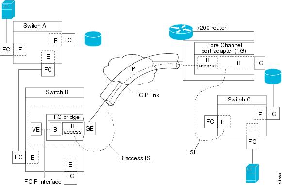
The IPS module supports FCIP links that originate from a B port SAN extender device by implementing the B access ISL protocol on a Gigabit Ethernet interface. Internally, the corresponding virtual B port connects to a virtual E port that completes the end-to-end E port connectivity requirement (see Figure 22-12).
Figure 22-12 FCIP Link Terminating in a B Port Mode
The B port feature in the IPS module allows remote B port SAN extenders to communicate directly with a Cisco MDS 9000 Family switch, therefore eliminating the need for local bridge devices.
Configuring B Ports
When a FCIP peer is a SAN extender device that only supports Fibre Channel B ports, you need to enable the B port mode for the FCIP link. When a B port is enabled, the E port functionality is also enabled and they coexist. If the B port is disabled, the E port functionality remains enabled.
To enable B port mode, follow these steps:
E Port Configurations
•
•
•
–
–
•
•
•
See "Configuring and Managing VSANs," "Configuring Trunking," "Configuring PortChannels," "Configuring Fibre Channel Routing Services and Protocols," "Configuring Domain Parameters," and "Configuring and Managing Zones."
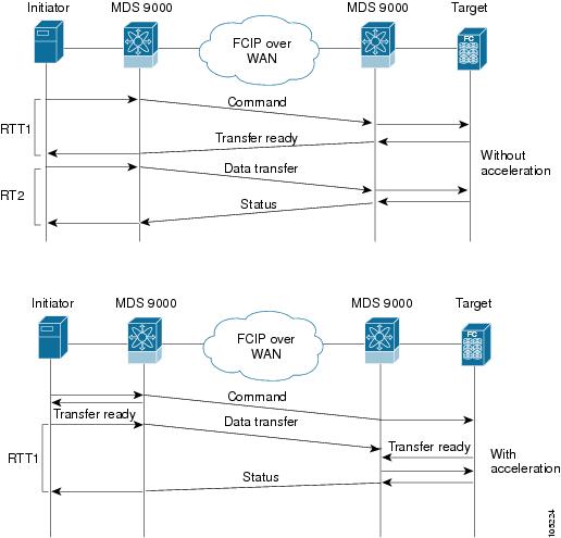
Configuring FCIP Write Acceleration
The FCIP write acceleration feature in SAN-OS 1.3(3) enables you to significantly improve application performance when storage traffic is routed over wide area networks using FCIP. When FCIP write acceleration is enabled, WAN throughput is maximized by minimizing the impact of WAN latency for the command to transfer ready acknowledgments (see Figure 22-13).
Note
Figure 22-13 FCIP Link Write Acceleration
In Figure 22-13, some data sent by the host is queued on the target before the target issues a Transfer Ready. This way the actual write operation may be done in less time than the write operation without the write acceleration feature being enabled.
Tip
Caution
To enable write acceleration, follow these steps:
Enabling FCIP Compression
The FCIP compression feature introduced in Cisco MDS SAN-OS Release 1.3(x) allows IP packets to be compressed on the FCIP link if this feature is enabled on that link. By default the FCIP compression is disabled.
This feature uses the Lempel-Ziv-Stac (LZS) compression algorithm to compress packets.
The high-throughput mode allows faster compression but the compression ratio may be lower. The high-comp-ratio mode allows a higher compression ratio, but the throughput may be lower.
To enable FCIP compression, follow these steps:
Displaying FCIP Information
Use the show interface commands to view the summary, counter, description, and status of the FCIP link. Use the output of these commands to verify the administration mode, the interface status, the operational mode, the related VSAN ID, and the profile used. See Examples 22-14 to 22-19.
Example 22-14 Displays the FCIP Interface
switch# show interface fcip 3fcip3 is trunkingHardware is GigabitEthernetPort WWN is 20:ca:00:05:30:00:07:1ePeer port WWN is 20:ca:00:00:53:00:18:1eAdmin port mode is auto, trunk mode is onPort mode is TEvsan is 1Trunk vsans (allowed active) (1,10)Trunk vsans (operational) (1)Trunk vsans (up) (1)Trunk vsans (isolated) (10)Trunk vsans (initializing) ()Using Profile id 3 (interface GigabitEthernet4/3)Peer InformationPeer Internet address is 43.1.1.1 and port is 3225Special Frame is disabledMaximum number of TCP connections is 2Time Stamp is disabledB-port mode disabledTCP Connection Information2 Active TCP connectionsControl connection: Local 43.1.1.2:3225, Remote 43.1.1.1:65532Data connection: Local 43.1.1.2:3225, Remote 43.1.1.1:6553430 Attempts for active connections, 0 close of connectionsTCP ParametersPath MTU 1500 bytesCurrent retransmission timeout is 300 msRound trip time: Smoothed 10 ms, Variance: 5Advertised window: Current: 122 KB, Maximum: 122 KB, Scale: 1Peer receive window: Current: 114 KB, Maximum: 114 KB, Scale: 1Congestion window: Current: 2 KB, Slow start threshold: 1048560 KB5 minutes input rate 64 bits/sec, 8 bytes/sec, 0 frames/sec5 minutes output rate 64 bits/sec, 8 bytes/sec, 0 frames/sec808 frames input, 75268 bytes808 Class F frames input, 75268 bytes0 Class 2/3 frames input, 0 bytes0 Error frames timestamp error 0806 frames output, 74712 bytes806 Class F frames output, 74712 bytes0 Class 2/3 frames output, 0 bytes0 Error frames 0 reass framesExample 22-15 Displays Detailed FCIP Interface Counter Information
switch# show interface fcip 3 countersfcip3TCP Connection Information2 Active TCP connectionsControl connection: Local 43.1.1.2:3225, Remote 43.1.1.1:65532Data connection: Local 43.1.1.2:3225, Remote 43.1.1.1:6553430 Attempts for active connections, 0 close of connectionsTCP ParametersPath MTU 1500 bytesCurrent retransmission timeout is 300 msRound trip time: Smoothed 10 ms, Variance: 5Advertised window: Current: 122 KB, Maximum: 122 KB, Scale: 1Peer receive window: Current: 114 KB, Maximum: 114 KB, Scale: 1Congestion window: Current: 2 KB, Slow start threshold: 1048560 KB5 minutes input rate 64 bits/sec, 8 bytes/sec, 0 frames/sec5 minutes output rate 64 bits/sec, 8 bytes/sec, 0 frames/sec814 frames input, 75820 bytes814 Class F frames input, 75820 bytes0 Class 2/3 frames input, 0 bytes0 Error frames timestamp error 0812 frames output, 75264 bytes812 Class F frames output, 75264 bytes0 Class 2/3 frames output, 0 bytes0 Error frames 0 reass framesExample 22-16 Displays Brief FCIP Interface Counter Information
switch# show interface fcip 3 counters brief-------------------------------------------------------------------------------Interface Input (rate is 5 min avg) Output (rate is 5 min avg)----------------------------- -----------------------------Rate Total Rate TotalMbits/s Frames Mbits/s Frames-------------------------------------------------------------------------------fcip3 9 0 9 0Example 22-17 Displays the FCIP Interface Description
switch# show interface fcip 51 descriptionFCIP51Sample FCIP interfaceExample 22-18 Displays FCIP Profiles
switch# show fcip profile-------------------------------------------------------------------------------ProfileId Ipaddr TcpPort-------------------------------------------------------------------------------1 10.10.100.150 32252 10.10.100.150 322640 40.1.1.2 3225100 100.1.1.2 3225200 200.1.1.2 3225Example 22-19 Displays the Specified FCIP Profile Information
switch# show fcip profile 7FCIP Profile 7Internet Address is 47.1.1.2 (interface GigabitEthernet4/7)Listen Port is 3225TCP parametersSACK is disabledPMTU discovery is enabled, reset timeout is 3600 secKeep alive is 60 secMinimum retransmission timeout is 300 msMaximum number of re-transmissions is 4Send buffer size is 0 KBMaximum allowed bandwidth is 1000000 kbpsMinimum available bandwidth is 15000 kbpsEstimated round trip time is 1000 usecExample 22-20 provides a sample output of FCIP counters when the write acceleration feature is enabled.
Example 22-20 Displays IP Compression Counters in a FCIP Interface
switch# show interface fcip 8 countersfcip8TCP Connection Information2 Active TCP connectionsControl connection: Local 10.2.2.1:3225, Remote 10.2.2.2:65439Data connection: Local 10.2.2.1:3225, Remote 10.2.2.2:654414 Attempts for active connections, 0 close of connectionsTCP ParametersPath MTU 1500 bytesCurrent retransmission timeout is 200 msRound trip time: Smoothed 2 ms, Variance: 1Advertized window: Current: 14 KB, Maximum: 14 KB, Scale: 9Peer receive window: Current: 14 KB, Maximum: 17 KB, Scale: 9Congestion window: Current: 10 KB, Slow start threshold: 112 KB5 minutes input rate 760 bits/sec, 95 bytes/sec, 0 frames/sec5 minutes output rate 912 bits/sec, 114 bytes/sec, 0 frames/sec9379771 frames input, 16906568212 bytes638 Class F frames input, 58752 bytes9379133 Class 2/3 frames input, 16906509460 bytes7908669 Reass frames0 Error frames timestamp error 09229787 frames output, 16569073984 bytes638 Class F frames output, 60128 bytes9229149 Class 2/3 frames output, 16569013856 bytes0 Error framesWrite Accelerator statistics18609558 packets in 10219163 packets out0 frames dropped 0 CRC errors0 rejected due to table full0 ABTS sent 6 ABTS received0 tunnel synchronization errors485136 writes recd 485136 XFER_RDY sent (host)485136 XFER_RDY rcvd (host)0 XFER_RDY not proxied due to flow control (host)0 bytes queued for sending0 estimated bytes queued on the other side for sending0 times TCP flow ctrl (target)0 bytes current TCP flow ctrl (target)IP compression statistics10044 rxbytes 0 rxbytes compressed10044 txbytes 6460 txbytes compressedFCIP High Availability
The following high availability solutions are available for FCIP configurations:
•
•
Fibre Channel PortChannels
Figure 22-14 provides an example of a PortChannel-based load balancing configuration. To perform this configuration, you need two IP addresses on each SAN island. This solution addresses link failures.
Figure 22-14 PortChannel Based Load Balancing
The following characteristics set Fibre Channel PortChannel solutions apart from other solutions:
•
•
•
FSPF
Figure 22-15 displays a FPSF-based load balancing configuration example. This configuration requires two IP addresses on each SAN island, and addresses IP and FCIP link failures.
Figure 22-15 FSPF-Based Load Balancing
The following characteristics set FSPF solutions apart from other solutions:
•
•
•
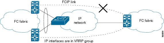
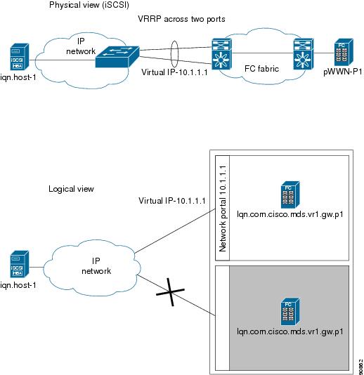
VRRP
Figure 22-16 displays a VRRP-based high availability FCIP configuration example. This configuration requires at least two physical Gigabit Ethernet ports connected to the Ethernet switch on the island where you need to implement high availability using VRRP.
Figure 22-16 VRRP-Based High Availability
The following characteristics set VRRP solutions apart from other solutions:
•
•
•
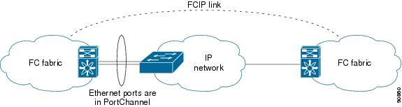
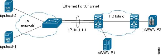
Ethernet PortChannels
Figure 22-17 displays an Ethernet PortChannel-based high availability FCIP example. This solution addresses the problem caused by individual Gigabit Ethernet link failures.
Figure 22-17 Ethernet PortChannel-Based High Availability
The following characteristics set Ethernet PortChannel solutions apart from other solutions:
•
•
•
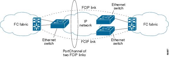
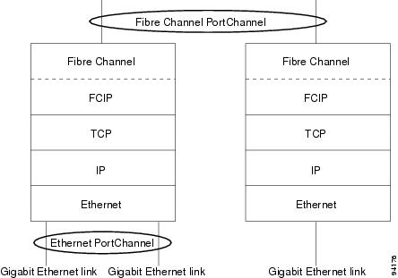
Ethernet PortChannels and Fibre Channel PortChannels
Ethernet PortChannels offer Ethernet-level redundancy and Fibre Channel PortChannels offer (E)ISL-level redundancy. FCIP is unaware of any Ethernet PortChannels or Fibre Channel PortChannels. Fibre Channel PortChannels are unaware of any Ethernet PortChannels, and there is no mapping between the two (see Figure 22-18).
Figure 22-18 PortChannels at the Fibre Channel and Ethernet Levels
To configure Fibre Channel PortChannels, see "Configuring PortChannels." To configure Ethernet PortChannels, see the "Ethernet PortChannel Aggregation" section.
Configuring iSCSI
This section includes the following topics:
•
•
•
•
•
•
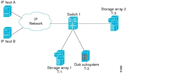
About iSCSI
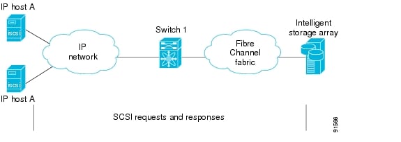
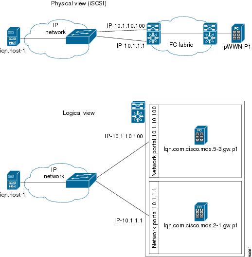
The IPS module provides transparent SCSI routing by default. IP hosts using the iSCSI protocol can transparently access targets on the Fibre Channel network. Figure 22-19 provides an example of a typical configuration of iSCSI hosts with access to a Fibre Channel SAN.
Figure 22-19 Typical IP to Fibre Channel SAN Configuration
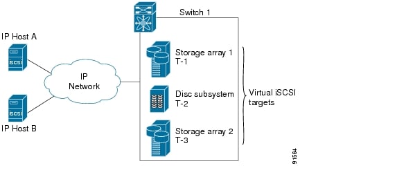
IPS modules enable you to create virtual iSCSI targets and then maps them to physical Fibre Channel targets available in the Fibre Channel SAN. They presents the Fibre Channel targets to IP hosts as if the physical targets were attached to the IP network (see Figure 22-20).
Figure 22-20 iSCSI View
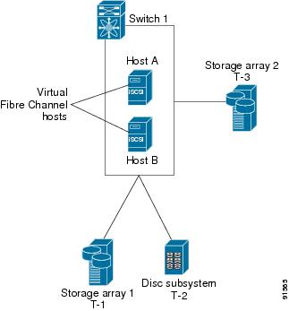
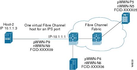
In conjunction with presenting Fibre Channel targets to iSCSI hosts, the IPS module presents each iSCSI host as a Fibre Channel host (in transparent mode), that is, a host bus adapter (HBA) to the Fibre Channel storage device. The storage device responds to each IP host as if it were a Fibre Channel host connected to the Fibre Channel network (see Figure 22-21).
Figure 22-21 Fibre Channel SAN View
Note
Enabling iSCSI
To begin configuring the iSCSI feature, you must explicitly enable iSCSI on the required switches in the fabric. By default, this feature is disabled in all switches in the Cisco MDS 9000 Family.
The configuration and verification commands for the iSCSI feature are only available when iSCSI is enabled on a switch. When you disable this feature, all related configurations are automatically discarded.
To enable iSCSI on any participating switch, follow these steps:
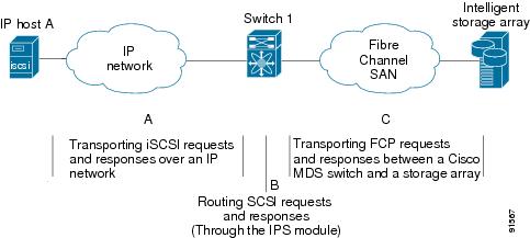
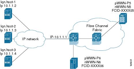
Routing iSCSI Requests and Responses
The iSCSI feature consists of routing iSCSI requests and responses between hosts in an IP network and Fibre Channel storage devices in the Fibre Channel SAN that are accessible from any Fibre Channel interface of the Cisco MDS 9000 Family switch (see Figure 22-22).
Figure 22-22 Routing iSCSI Requests and Responses for Transparent iSCSI Routing
Each iSCSI host that requires access to storage through the IPS module needs to have a compatible iSCSI driver installed. (The Cisco.com website at http://www.cisco.com/pcgi-bin/tablebuild.pl/sn5420-scsi provides a list of compatible drivers). Using the iSCSI protocol, the iSCSI driver allows an iSCSI host to transport SCSI requests and responses over an IP network. From the host operating system perspective, the iSCSI driver appears to be a SCSI transport driver similar to a Fibre Channel driver for a peripheral channel in the host. From the storage device perspective, each IP host appears as a Fibre Channel host.
Routing SCSI from the IP host to the Fibre Channel storage device consists of the following main actions (see Figure 22-23):
•
•
•
Figure 22-23 Transparent SCSI Routing Actions
Note
Presenting Fibre Channel Targets as iSCSI Targets
The IPS module presents physical Fibre Channel targets as iSCSI targets allowing them to be accessed by iSCSI hosts. It does this in one of two ways:
•
•
Note
Dynamic Importing
The IPS module maps each physical Fibre Channel target port as one iSCSI target. That is, all LU accessible through the physical storage target port are available as iSCSI LUs with the same LU number (LUN) as in the storage target.
For example, if an iSCSI target was created for a Fibre Channel target port with pWWN 31:00:11:22:33:44:55:66 and that pWWN contains LUN 0 through 2, those LUNs would become available to an IP host as LUNs 0 through 2 as well.
Note
The iSCSI target node name is created automatically using the iSCSI qualified name (IQN) format. The iSCSI qualified name is restricted to a maximum name length of 223 alphanumeric characters and a minimum length of 16 characters.
The IPS module creates an IQN formatted iSCSI node name using the following conventions:
•
iqn.1987-05.com.cisco:05.<mgmt-ip-address>.<slot#>-<port#>-<sub-intf#>.<Target-pWWN>•
iqn.1987-05.com.cisco:05.vrrp-<vrrp-ID#>-<vrrp-IP-addr>.<Target-pWWN>•
iqn.1987-02.com.cisco:05.<mgmt-ip-address>.pc-<port-ch-sub-intf#>.<Target-pWWN>
Note
Use the iscsi import target fc command to enable dynamic importing of Fibre Channel targets into iSCSI.
To dynamically import Fibre Channel targets, follow these steps:
Static Importing
You can manually (statically) create an iSCSI target and assign a node name to it. A statically mapped iSCSI target can either contain the whole FC target port, or it can contain one or more LUs from a Fibre Channel target port.
To create a static iSCSI virtual target for the entire Fibre Channel target port, follow these steps:
See the "iSCSI-Based Access Control" section for more information on controlling access to statically-imported targets.
For multiple interfaces configured with iSNS (see the "Configuring Storage Name Services" section), a different static virtual target name has to be created for each interface tagged to an iSNS profile and each static virtual target must be advertised only from one interface (see the "Advertising iSCSI Targets" section)
Advertising iSCSI Targets
You can limit the Gigabit Ethernet interfaces over which static iSCSI targets are advertised. By default iSCSI targets are advertised on all Gigabit Ethernet interfaces, subinterfaces, PortChannel interfaces, and PortChannel subinterfaces.
To configure a specific interface that should be advertised by a static iSCSI virtual target, follow these steps:
High Availability Static Target Importing
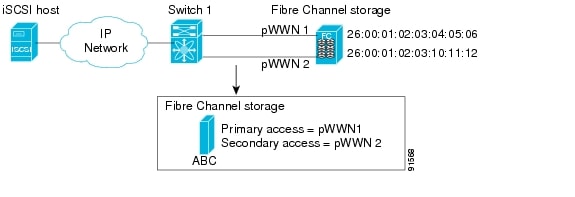
Statically imported iSCSI targets have an additional option to provide a secondary pWWN for the Fibre Channel target. This can be used when the physical Fibre Channel target is configured to have an LU visible across redundant ports. When the active port fails, the secondary port becomes active and the iSCSI session switches to use the new active port (see Figure 22-24).
Figure 22-24 Static Target Importing Through Two Fibre Channel Ports
In Figure 22-24, you can create a virtual iSCSI target that is mapped to both pWWN1 and pWWN2 to provide redundant access to the Fibre Channel targets.
The failover to secondary port is done transparently by the IPS port without impacting the iSCSI session from the host. All outstanding I/O are terminated with a check condition status when the primary port fails. New I/O received while the failover has not completed will receive a busy status.
Tip
Enable the optional revert-primary-port option to direct the IPS port to switch back to the primary port when the primary port is up again. If this option is disabled (default) and the primary port is up again after a switchover, the old sessions will remain with the secondary port and does not switch back to the primary port. However, any new session will use the primary port. This is the only situation when both the primary and secondary ports are used at the same time.
To create a static iSCSI virtual target, follow these steps:
Storage Port Failover LUN Trespass
In addition to the high availability of statically imported iSCSI targets, the trespass feature is available (as of Cisco MDS SAN-OS Release 1.3(x)) to enable the export of LUs, on an active port failure, from the active to the passive port of a statically imported iSCSI target.
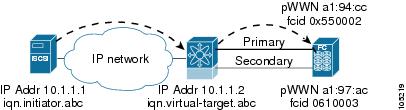
In physical Fibre Channel targets, which are configured to have LUs visible over two Fibre Channel N-ports, when the active port fails, the passive port takes over. Some physical Fibre Channel targets require that the trespass command be issued to export the LUs from the active port to the passive port. A statically imported iSCSI target's secondary pWWN option and an additional option of enabling the trespass feature is available for a physical Fibre Channel target with redundant ports. When the active port fails, the passive port becomes active, and if the trespass feature is enabled, the Cisco MDS switch issues a trespass command to the target to export the LUs on the new active port. The iSCSI session switches to use the new active port and the exported LUs are accessed over the new active port (see Figure 22-25).
Figure 22-25 Virtual Target with an Active Primary Port
To enable the trespass feature for a static iSCSI virtual target, follow these steps:
Use the show iscsi virtual-target command to verify.
switch# show iscsi virtual-target iqn.1987-02.com.cisco.initiatortarget: 1987-02.com.cisco.initiatorPort WWN 00:00:00:00:00:00:00:00Configured nodeall initiator permit is disabledtrespass support is enablediSCSI Virtual Target Configuration Examples
This section provides three examples of virtual target configurations.
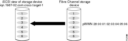
Example 1
This example assigns the whole Fibre Channel target as a virtual iSCSI target. All LUNs that are part of the Fibre Channel target are available as part of the iSCSI target (see Figure 22-26).
iscsi virtual-target name iqn.1987-02.com.cisco.initiator-1pWWN 28:00:01:02:03:04:05:06Figure 22-26 Assigning iSCSI Node Names
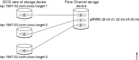
Example 2
This example maps a subset of LUNs of a Fibre Channel target to three iSCSI virtual targets. Each iSCSI target only has one LUN (see Figure 22-27).
iscsi virtual-target name iqn.1987-02.com.cisco.initiator-1pWWN 28:00:01:02:03:04:05:06 fc-lun 0 iscsi-lun 0iscsi virtual-target name iqn.1987-02.com.cisco.initiator-2pWWN 28:00:01:02:03:04:05:06 fc-lun 1 iscsi-lun 0iscsi virtual-target name iqn.1987-02.com.cisco.initiator-3pWWN 28:00:01:02:03:04:05:06 fc-lun 2 iscsi-lun 0Figure 22-27 Mapping LUNs to a iSCSI Node Name
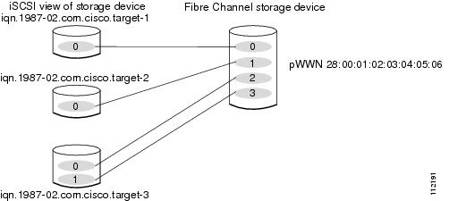
Example 3
This example maps three subsets of Fibre Channel LUN targets to three iSCSI virtual targets. Two iSCSI targets have one LUN and the third iSCSI target has two LUNs (see Figure 22-28).
iscsi virtual-target name iqn.1987-02.com.cisco.initiator-1pWWN 28:00:01:02:03:04:05:06 fc-lun 0 iscsi-lun 0iscsi virtual-target name iqn.1987-02.com.cisco.initiator-2pWWN 28:00:01:02:03:04:05:06 fc-lun 1 iscsi-lun 0iscsi virtual-target name iqn.1987-02.com.cisco.initiator-3pWWN 28:00:01:02:03:04:05:06 fc-lun 2 iscsi-lun 0pWWN 28:00:01:02:03:04:05:06 fc-lun 3 iscsi-lun 1Figure 22-28 Mapping LUNs to Multiple iSCSI Node Names
Presenting iSCSI Hosts as Virtual Fibre Channel Hosts
The iSCSI hosts are mapped to virtual Fibre Channel hosts in one of two ways (see Figure 22-21):
•
•
Dynamic Mapping
When an iSCSI host connects to the IPS module using the iSCSI protocol, a virtual N port is created for the host. The nWWNs and pWWNs are dynamically allocated from the switch's Fibre Channel WWN pool. The IPS module registers this N port in the Fibre Channel SAN. The IPS module continues using that nWWN and pWWN to represent this iSCSI host until it no longer has a connection to any iSCSI target through that IP storage port.
At that point, the virtual Fibre Channel host is taken offline from the Fibre Channel SAN and the nWWNs and pWWNs are released back to the switch's Fibre Channel WWN pool. These addresses become available for assignment to other iSCSI hosts requiring access to Fibre Channel SANs. When a dynamically mapped iSCSI initiator has multiple sessions to multiple Fibre Channel targets, each session can use the same pWWN and nWWN as long as it uses the same node name in the iSCSI login message.
If the host has multiple network interfaces (each having different IP addresses), you can treat each IP address as a different iSCSI initiator host by using the switchport initiator id ip-address command.
Identifying Initiators
By default, the switch uses the iSCSI node name to identify the initiator.
An iSCSI initiator is identified in one of two ways:
•
•
Use the switchport initiator id name command to identify the iSCSI initiator using the iSCSI node name and the switchport initiator id ip-address command to identify the iSCSI initiator using the IP address,
To identify the initiator using the IP address, follow these steps:
Static Mapping
With dynamic mapping, each time the iSCSI host connects to the IPS module a new Fibre Channel N port is created and the nWWNs and pWWNs allocated for this N port may be different. Use the static mapping method to obtain the same nWWN and pWWNs for the iSCSI host each time it connects to the IPS module.
Static mapping can be used on the IPS module to access intelligent Fibre Channel storage arrays that have access control and LUN mapping or masking configuration based on the initiator's pWWNs and/or nWWNs.
Note
You can implement static mapping in one of two ways:
•
•
This assignment uses the system-assign option.
Tip
To configure static mapping (using the name option) for an iSCSI initiator, follow these steps:
To configure static mapping (using the ip-address option) for an iSCSI initiator, follow these steps:
To assign the WWN for an iSCSI initiator, follow these steps:
Note
Making the Dynamic Initiator WWN Mapping Static
After a dynamic initiator has already logged in, you may decide to permanently keep the automatically assigned nWWN/pWWN mapping, so this initiator uses the same mapping the next time it logs in.
To permanently keep the automatically assigned nWWN/pWWN mapping, follow these steps:
Assigning VSAN Membership to iSCSI Hosts
By default, a host is only in VSAN 1 (default VSAN). You can configure an iSCSI host to be a member of one or more VSANs. The IPS module creates one Fibre Channel virtual N port in each VSAN to which the host belongs.
To assign VSAN membership for iSCSI hosts, follow these steps:
Note
Assigning VSANs to a iSCSI Interface
All dynamic iSCSI initiators are members of VSAN 1. The port VSAN of an iSCSI interface is the default VSAN for all dynamic iSCSI initiators. All dynamic iSCSI initiators are members of the port VSAN of the iSCSI interface. The default port VSAN of an iSCSI interface is VSAN 1.
Use the vsan vsan-number interface iscsi slot/port command in the VSAN database submode to change the default port VSAN.
Tip
To change the default port VSAN, follow these steps:
Configuring iSCSI Proxy Initiators
Note
By default, each iSCSI initiator appears as one Fibre Channel initiator in transparent mode in the Fibre Channel fabric. For some storage arrays, this appearance requires the initiator's pWWN to be manually configured for access control purposes. This process can be quite cumbersome. The proxy initiator feature allows all iSCSI initiators to connect through one IPS port making it appear as one Fibre Channel port per VSAN. It simplifies the task of configuring the pWWN for each new initiator on the storage array, and of configuring Fibre Channel access control such as zoning. This feature along with static target importing (using LUN mapping) results in the configuration being performed only on the switch when a new iSCSI host is added. On the storage array, all LUNs that are used by iSCSI initiators are configured to allow access by the proxy initiator's pWWN. From the iSCSI perspective, this configuration is no different from the default mode (see Figure 22-29).
Figure 22-29 iSCSI View of a Proxy Initiator
From the Fibre Channel perspective, only one Fibre Channel initiator is visible per VSAN (see Figure 22-30).
Figure 22-30 FC View with a Proxy Initiator
To configure the proxy initiator, follow these steps:
To verify the proxy initiator mode configuration, use the show interface iscsi command in EXEC mode (see the "Displaying Proxy Initiator Information" section).
iSCSI Initiator Idle Timeout
iSCSI initiator idle timeout specifies the time for which the initiator information is kept after the initiator logs out. The default is 300 seconds.
To configure the initiator idle timeout, follow these steps:
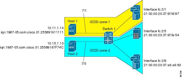
Access Control in iSCSI
You can control access to each statically mapped iSCSI target by specifying a list of IPS ports on which it is advertised and specifying a list of iSCSI initiator node names allowed to access it. Fibre Channel zoning-based access control and iSCSI-based access control are the two mechanisms by which access control can be provided for iSCSI. Both methods can be used simultaneously.
Note
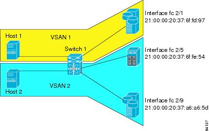
Fibre Channel Zoning-Based Access Control
Zoning is an access control mechanism within a VSAN. The switch's zoning implementation extends the VSAN and zoning concepts from the Fibre Channel domain to cover the iSCSI domain. This extension includes both iSCSI and Fibre Channel features and provides a uniform, flexible access control across a SAN. There are two Fibre Channel zoning access control mechanisms--static and dynamic.
•
•
To register an iSCSI initiator in the zone database, follow these steps:
iSCSI-Based Access Control
For static iSCSI targets, you can manually configure a list of iSCSI initiators that are allowed to access the targets. The iSCSI initiator is identified by the iSCSI node name or the IP address of the iSCSI host.
By default, static virtual iSCSI targets are not accessible to any iSCSI host. You must explicitly configure accessibility to allow a virtual iSCSI target to be accessed by all hosts. The initiator access list can contain one or more initiators. Each initiator is identified by one of the following:
•
•
•
To configure access control in iSCSI, follow these steps:
Enforcing Access Control
IPS modules use both iSCSI node name-based and Fibre Channel zoning-based access control lists to enforce access control during iSCSI discovery and iSCSI session creation.
•
•
The IPS module then creates a Fibre Channel virtual N port (the N port may already exist) for this IP host and does a Fibre Channel name server query for the FCID of the Fibre Channel target pWWN that is being accessed by the IP host. It uses the IP host virtual N port's pWWN as the requester of the name server query. Thus, the name server does a zone-enforced query for the pWWN and responds to the query.
If the FCID is returned by the name server, then the iSCSI session is accepted. Otherwise, the login request is rejected.
Note
iSCSI User Authentication
The IPS module supports the iSCSI authentication mechanism to authenticate iSCSI hosts that request access to storage. By default, IPS modules allow CHAP or None authentication of iSCSI initiators. When iSCSI authentication is enabled, the iSCSI hosts must provide user name and password information each time an iSCSI session is established.
Note
You can use RADIUS authentication (see the "Configuring RADIUS" section) or TACACS+ authentication (see the "Configuring TACACS+" section). If no authentication is configured, local authentication is used.
The aaa authentication iscsi default command enables aaa authentication for the iSCSI host.
To configure AAA authentication for an iSCSI user, follow these steps:
Authentication Mechanism
During an iSCSI login, both the iSCSI initiator and target have the option to authenticate each other. By default, the IPS module allows either CHAP authentication or no authentication from iSCSI hosts.
Note
If CHAP authentication should always be used, issue the iscsi authentication chap command at either the global level or at a per-interface level. If authentication should not be used, issue the iscsi authentication none command.
To configure the authentication mechanism for iSCSI, follow these steps:
To configure the authentication policy for iSCSI sessions to a particular interface, follow these steps:
The IPS module verifies the iSCSI host authentication using the local password database, TACACS+, or RADIUS (see the "Configuring CLI User Profiles" section). If local authentication is used, the username iscsi-user password iscsi command assigns a password and a user name for a new user. If the user name does not exist it is created.
Note
To configure iSCSI users for local authentication, follow these steps:
You can restrict an initiator to use a specified CHAP username to connect to a Cisco MDS switch. This configuration is in addition to configuring the iSCSI username and password,
To restrict an initiator to use a specified CHAP username, follow these steps:
Advanced iSCSI Configuration
Advanced configuration options are available for iSCSI interfaces on a per-IPS port basis. These configurations are similar to the advanced FCIP configurations and are already explained in that section (see the Advanced FCIP Profile Configuration).
To access these commands from the iSCSI interface, follow these steps:
Cisco MDS switches support the following advanced features for iSCSI interfaces:
•
See the "Configuring TCP Listener Ports" section)
•
–
See the "Minimum Retransmit Timeout" section, "Keepalive Timeout" section, "Maximum Retransmissions" section, "Path MTU" section, "Monitoring Window Congestion" section and "Estimating Maximum Delay Jitter" section.
–
•
•
iSCSI Forwarding Mode
The iSCSI gateway on the IPS module has two modes of forwarding operation:
•
•
Tip
Displaying iSCSI Information
This section includes the following topics:
•
•
•
Displaying iSCSI Interfaces
Use the show iscsi interface command to view the summary, counter, description, and status of the iSCSI interface. Use the output to verify the administrative mode, the interface status, TCP parameters currently used, and brief statistics. See Example 22-21.
Example 22-21 Displays the iSCSI Interface Information
switch# show interface iscsi 2/1iscsi2/1 is up --------------------------> Interface is upHardware is GigabitEthernetPort WWN is 20:41:00:05:30:00:50:deAdmin port mode is ISCSIPort mode is ISCSISpeed is 1 GbpsiSCSI initiator is identified by nameNumber of iSCSI session: 7, Number of TCP connection: 7Configured TCP parametersLocal Port is 3260PMTU discover is disabledKeepalive-timeout is 1 secMinimum-retransmit-time is 300 msMax-retransmissions 8Sack is disabledMinimum available bandwidth is 0 kbpsEstimated round trip time is 0 usec5 minutes input rate 265184 bits/sec, 33148 bytes/sec, 690 frames/sec5 minutes output rate 375002168 bits/sec, 46875271 bytes/sec, 33833 frames/seciSCSI statistics6202235 packets input, 299732864 bytesCommand 6189718 pdus, Data-out 1937 pdus, 1983488 bytes, 0 fragments146738794 packets output, 196613551108 bytesResponse 6184282 pdus (with sense 4), R2T 547 pdusData-in 140543388 pdus, 189570075420 bytesThe show iscsi stats command can be used to view brief or detailed iSCSI statistics per iSCSI interface. See Examples 22-22 and 22-23.
Example 22-22 Displays iSCSI Statistics for the iSCSI Interface
switch# show iscsi stats iscsi 2/1iscsi2/15 minutes input rate 0 bits/sec, 0 bytes/sec, 0 frames/sec5 minutes output rate 0 bits/sec, 0 bytes/sec, 0 frames/seciSCSI statistics3568 packets input, 1134600 bytesCommand 2930 pdus, Data-out 471 pdus, 939008 bytes, 0 fragmentsoutput 13418 packets, 10785796 bytesResponse 2930 pdus (with sense 18), R2T 235 pdusData-in 10086 pdus, 10134572 bytesExample 22-23 Displays Detailed iSCSI Statistics for the iSCSI Interface
switch# show iscsi stats iscsi 2/1 detailiscsi2/15 minutes input rate 0 bits/sec, 0 bytes/sec, 0 frames/sec
Note
5 minutes output rate 0 bits/sec, 0 bytes/sec, 0 frames/sec
Note
iSCSI statistics3568 packets input, 1134600 bytes
Note
Command 2930 pdus, Data-out 471 pdus, 939008 bytes, 0 fragments
Note
output 13418 packets, 10785796 bytes
Note
Response 2930 pdus (with sense 18), R2T 235 pdus
Note
Data-in 10086 pdus, 10134572 bytes
Note
iSCSI Forward:Command: 2930 PDUs (Rcvd: 2930)
Note
Data-Out (Write): 471 PDUs (Rcvd 471), 0 fragments, 939008 bytes
Note
FCP Forward:Xfer_rdy: 235 (Rcvd: 240)
Note
Data-In: 10086 (Rcvd: 10093), 10134572 bytes
Note
Response: 2930 (Rcvd: 2942), with sense 18
Note
TMF Resp: 0
Note
iSCSI Stats:Login: attempt: 40, succeed: 9, fail: 31, authen fail: 0
Note
Rcvd: NOP-Out: 13, Sent: NOP-In: 13
Note
NOP-In: 0, Sent: NOP-Out: 0
Note
TMF-REQ: 0, Sent: TMF-RESP: 0
Note
Text-REQ: 2, Sent: Text-RESP: 2
Note
SNACK: 0
Note
Unrecognized Opcode: 0, Bad header digest: 0
Note
Command in window but not next: 0, exceed wait queue limit: 0
Note
Received PDU in wrong phase: 0
Note
SCSI Busy responses: 0
Note
FCP Stats:Total: Sent: 3733 (number of FCP frames sent out on the FC side)Received: 13373 (Error: 0, Unknown: 0)
Note
Sent: PLOGI: 38, Rcvd: PLOGI_ACC: 38, PLOGI_RJT: 0
Note
PRLI: 100, Rcvd: PRLI_ACC: 7, PRLI_RJT: 0, Error: 0, From initiator: 0
Note
LOGO: 35, Rcvd: LOGO_ACC: 0, LOGO_RJT: 0
Note
PRLO: 4, Rcvd: PRLO_ACC: 0, PRLO_RJT: 0
Note
ABTS: 93, Rcvd: ABTS_ACC: 0
Note
TMF REQ: 0
Note
Self orig command: 7, Rcvd: data: 7, resp: 7
Note
Rcvd: PLOGI: 35, Sent: PLOGI_ACC: 33, PLOGI_RJT: 2
Note
LOGO: 4, Sent: LOGO_ACC: 4, LOGO_RJT: 0
Note
PRLI: 6, Sent: PRLI_ACC: 6, PRLI_RJT: 0
Note
PRLO: 0, Sent: PRLO_ACC: 0, PRLO_RJT: 0
Note
ABTS: 0
Note
iSCSI Drop:Command: Target down 0, Task in progress 0, LUN map fail 0CmdSeqNo not in window 0, No Exchange ID 0, Reject 0No task: 0
Note
Data-Out: 0, Data CRC Error: 0
Note
TMF-Req: 0, No task: 0
Note
FCP Drop:Xfer_rdy: 0, Data-In: 0, Response: 0
Note
Buffer Stats:Buffer less than header size: 0, Partial: 477, Split: 237Pullup give new buf: 0, Out of contiguous buf: 0, Unaligned m_data: 0
Note
Displaying Proxy Initiator Information
If the proxy initiator feature is enabled in the iSCSI interface, use the show interface iscsi command to display configured proxy initiator information (see Examples 22-24 and 22-25).
Example 22-24 Displays Proxy Initiator Information for the iSCSI Interface with System-Assigned WWNs
switch# show interface iscsi 4/1iscsi4/1 is upHardware is GigabitEthernetPort WWN is 20:c1:00:05:30:00:a7:9eAdmin port mode is ISCSIPort mode is ISCSISpeed is 1 GbpsiSCSI initiator is identified by nameNumber of iSCSI session: 0, Number of TCP connection: 0Configured TCP parametersLocal Port is 3260PMTU discover is enabled, reset timeout is 3600 secKeepalive-timeout is 60 secMinimum-retransmit-time is 300 msMax-retransmissions 4Sack is disabledQOS code point is 0Forwarding mode: pass-thruTMF Queueing Mode : disabledProxy Initiator Mode : enabled<----------------------------Proxy initiator is enablednWWN is 28:00:00:05:30:00:a7:a1 (system-assigned)<----System-assigned nWWNpWWN is 28:01:00:05:30:00:a7:a1 (system-assigned)<---- System-assigned pWWN5 minutes input rate 0 bits/sec, 0 bytes/sec, 0 frames/sec5 minutes output rate 0 bits/sec, 0 bytes/sec, 0 frames/seciSCSI statisticsInput 7 packets, 2912 bytesCommand 0 pdus, Data-out 0 pdus, 0 bytesOutput 7 packets, 336 bytesResponse 0 pdus (with sense 0), R2T 0 pdusData-in 0 pdus, 0 bytesExample 22-25 Displays Proxy Initiator Information for the iSCSI Interface with User-Assigned WWNs
switch# show interface iscsi 4/2iscsi4/2 is upHardware is GigabitEthernetPort WWN is 20:c1:00:05:30:00:a7:9eAdmin port mode is ISCSIPort mode is ISCSISpeed is 1 GbpsiSCSI initiator is identified by nameNumber of iSCSI session: 0, Number of TCP connection: 0Configured TCP parametersLocal Port is 3260PMTU discover is enabled, reset timeout is 3600 secKeepalive-timeout is 60 secMinimum-retransmit-time is 300 msMax-retransmissions 4Sack is disabledQOS code point is 0Forwarding mode: pass-thruTMF Queueing Mode : disabledProxy Initiator Mode : enablednWWN is 11:11:11:11:11:11:11:11 (manually-configured)<----User-assigned nWWNpWWN is 22:22:22:22:22:22:22:22 (manually-configured)<----User-assigned pWWN5 minutes input rate 0 bits/sec, 0 bytes/sec, 0 frames/sec5 minutes output rate 0 bits/sec, 0 bytes/sec, 0 frames/seciSCSI statisticsInput 7 packets, 2912 bytesCommand 0 pdus, Data-out 0 pdus, 0 bytesOutput 7 packets, 336 bytesResponse 0 pdus (with sense 0), R2T 0 pdusData-in 0 pdus, 0 bytesDisplaying Global iSCSI Information
Use the show iscsi global command to view the overall configuration and the iSCSI status. See Example 22-26.
Example 22-26 Displays the Current Global iSCSI Configuration and State
switch# show iscsi globaliSCSI Global informationAuthentication: NONEImport FC Target: EnabledNumber of target nodes: 5Number of portals: 8Number of sessions: 6Failed session: 0, Last failed initiator name:Displaying iSCSI Sessions
Use the show iscsi session command to view details about the current iSCSI sessions in the switch. Without parameters, this command displays all sessions. The output can be filtered by specifying an initiator, a target, or both.
Example 22-27 displays one iSCSI initiator configured based on the IQN name (iqn.1987-05.com.cisco:02.3021b0f2fda0.avanti12-w2k) and another based on its IP address (10.10.100.199).
Example 22-27 Displays Brief Information of All iSCSI Sessions
switch# show iscsi sessionInitiator iqn.1987-05.com.cisco:02.3021b0f2fda0.avanti12-w2kInitiator ip addr (s): 10.10.100.116Session #1Discovery session, ISID 00023d000043, Status activeSession #2Target VT1VSAN 1, ISID 00023d000046, Status active, no reservationSession #3Target VT2VSAN 1, ISID 00023d000048, Status active, no reservationInitiator 10.10.100.199Initiator name iqn.1987-05.com.cisco.01.7e3183ae458a94b1cd6bc168cba09d2eSession #1Target VT2VSAN 1, ISID 246700000000, Status active, no reservationSession #2Target VT1VSAN 1, ISID 246b00000000, Status active, no reservationSession #3Target iqn.1987-05.com.cisco:05.switch.04-01.2100002037a6be32VSAN 1, ISID 246e00000000, Status active, no reservationExample 22-28 and Example 22-29 display the iSCSI initiator configured based on its IP address (10.10.100.199).
Example 22-28 Displays Brief Information About the Specified iSCSI Session
switch# show iscsi session initiator 10.10.100.199 target VT1Initiator 10.10.100.199Initiator name iqn.1987-05.com.cisco.01.7e3183ae458a94b1cd6bc168cba09d2eSession #1Target VT1VSAN 1, ISID 246b00000000, Status active, no reservationExample 22-29 Displays Detailed Information About the Specified iSCSI Session
switch# show iscsi session initiator 10.10.100.199 target VT1 detailInitiator 10.10.100.199 (oasis-qa)Initiator name iqn.1987-05.com.cisco.01.7e3183ae458a94b1cd6bc168cba09d2eSession #1 (index 3)Target VT1VSAN 1, ISID 246b00000000, TSIH 384, Status active, no reservationType Normal, ExpCmdSN 39, MaxCmdSN 54, Barrier 0MaxBurstSize 0, MaxConn 0, DataPDUInOrder NoDataSeqInOrder No, InitialR2T Yes, ImmediateData NoRegistered LUN 0, Mapped LUN 0Stats:PDU: Command: 38, Response: 38Bytes: TX: 8712, RX: 0Number of connection: 1Connection #1Local IP address: 10.10.100.200, Peer IP address: 10.10.100.199CID 0, State: LOGGED_INStatSN 62, ExpStatSN 0MaxRecvDSLength 1024, our_MaxRecvDSLength 1392CSG 3, NSG 3, min_pdu_size 48 (w/ data 48)AuthMethod none, HeaderDigest None (len 0), DataDigest None (len 0)Version Min: 2, Max: 2FC target: Up, Reorder PDU: No, Marker send: No (int 0)Received MaxRecvDSLen key: NoDisplaying iSCSI Initiators
Use the show iscsi initiator command to display information about all initiators connected to an iSCSI interface in the switch. The information can be filtered to display only the desired iSCSI initiator by specifying the initiator name. Detailed output of the iscsi initiator can be obtained by specifying the detail option. The iscsi-session (and optionally detail) parameter displays only iSCSI session information. The fcp-session (and optionally detail) parameter displays only FCP session information. The output includes static and dynamic initiators. See Examples 22-30 and 22-31.
Example 22-30 Displays Information About Connected iSCSI Initiators
switch# show iscsi initiatoriSCSI Node name is iqn.1987-05.com.cisco:02.3021b0f2fda0.avanti12-w2kInitiator ip addr (s): 10.10.100.116iSCSI alias name: AVANTI12-W2KNode WWN is 22:01:00:05:30:00:10:e1 (configured)Member of vsans: 1, 2, 10Number of Virtual n_ports: 1Virtual Port WWN is 22:04:00:05:30:00:10:e1 (configured)Interface iSCSI 4/1, Portal group tag: 0x180VSAN ID 1, FCID 0x6c0202VSAN ID 2, FCID 0x6e0000VSAN ID 10, FCID 0x790000iSCSI Node name is 10.10.100.199iSCSI Initiator name: iqn.1987-05.com.cisco.01.7e3183ae458a94b1cd6bc168cba09d2eiSCSI alias name: oasis-qaNode WWN is 22:03:00:05:30:00:10:e1 (configured)Member of vsans: 1, 5Number of Virtual n_ports: 1Virtual Port WWN is 22:00:00:05:30:00:10:e1 (configured)Interface iSCSI 4/1, Portal group tag: 0x180VSAN ID 5, FCID 0x640000VSAN ID 1, FCID 0x6c0203Example 22-31 Displays Detailed Information About the iSCSI Initiator
switch# show iscsi initiator iqn.1987-05.com.cisco:02.3021b0f2fda0.avanti12-w2k detailiSCSI Node name is iqn.1987-05.com.cisco:02.3021b0f2fda0.avanti12-w2kInitiator ip addr (s): 10.10.100.116iSCSI alias name: AVANTI12-W2KNode WWN is 22:01:00:05:30:00:10:e1 (configured)Member of vsans: 1, 2, 10Number of Virtual n_ports: 1Virtual Port WWN is 22:04:00:05:30:00:10:e1 (configured)Interface iSCSI 4/1, Portal group tag is 0x180VSAN ID 1, FCID 0x6c02021 FC sessions, 1 iSCSI sessionsiSCSI session details <-------------------iSCSI session detailsTarget: VT1Statistics:PDU: Command: 0, Response: 0Bytes: TX: 0, RX: 0Number of connection: 1TCP parametersLocal 10.10.100.200:3260, Remote 10.10.100.116:4190Path MTU: 1500 bytesRetransmission timeout: 310 msRound trip time: Smoothed 160 ms, Variance: 38Advertized window: Current: 61 KB, Maximum: 62 KB, Scale: 0Peer receive window: Current: 63 KB, Maximum: 63 KB, Scale: 0Congestion window: Current: 1 KBFCP Session details <-------------------FCP session detailsTarget FCID: 0x6c01e8 (S_ID of this session: 0x6c0202)pWWN: 21:00:00:20:37:62:c0:0c, nWWN: 20:00:00:20:37:62:c0:0cSession state: CLEANUP1 iSCSI sessions share this FC sessionTarget: VT1Negotiated parametersRcvDataFieldSize 1392 our_RcvDataFieldSize 1392MaxBurstSize 0, EMPD: FALSERandom Relative Offset: FALSE, Sequence-in-order: YesStatistics:PDU: Command: 0, Response: 0Use the show fcns database (and optionally detail) to display the Fibre Channel name server entry for the Fibre Channel N port created for iSCSI initiators in the SAN. See Examples 22-32 and 22-35.
Example 22-32 Displays the FCNS Database Contents
switch# show fcns databaseVSAN 1:--------------------------------------------------------------------------FCID TYPE PWWN (VENDOR) FC4-TYPE:FEATURE--------------------------------------------------------------------------0x020101 N 22:04:00:05:30:00:35:e1 (Cisco) scsi-fcp:init isc..w <--iSCSI0x020102 N 22:02:00:05:30:00:35:e1 (Cisco) scsi-fcp:init isc..w initiator0x0205d4 NL 21:00:00:04:cf:da:fe:c6 (Seagate) scsi-fcp:target0x0205d5 NL 21:00:00:04:cf:e6:e4:4b (Seagate) scsi-fcp:target0x0205d6 NL 21:00:00:04:cf:e6:21:ac (Seagate) scsi-fcp:target0x0205d9 NL 21:00:00:04:cf:e6:19:9b (Seagate) scsi-fcp:target0x0205da NL 21:00:00:04:cf:e6:19:62 (Seagate) scsi-fcp:target0x0205dc NL 21:00:00:04:cf:e6:e9:82 (Seagate) scsi-fcp:target0x0205e0 NL 21:00:00:04:cf:e6:21:06 (Seagate) scsi-fcp:target0x0205e1 NL 21:00:00:04:cf:e6:e0:eb (Seagate) scsi-fcp:targetTotal number of entries = 10VSAN 2:--------------------------------------------------------------------------FCID TYPE PWWN (VENDOR) FC4-TYPE:FEATURE--------------------------------------------------------------------------0xef0001 N 22:02:00:05:30:00:35:e1 (Cisco) scsi-fcp:init isc..wTotal number of entries = 1VSAN 3:--------------------------------------------------------------------------FCID TYPE PWWN (VENDOR) FC4-TYPE:FEATURE--------------------------------------------------------------------------0xed0001 N 22:02:00:05:30:00:35:e1 (Cisco) scsi-fcp:init isc..wTotal number of entries = 1Example 22-33 Displays the FCNS Database in Detail
switch# show fcns database detail------------------------VSAN:1 FCID:0x020101------------------------port-wwn (vendor) :22:04:00:05:30:00:35:e1 (Cisco)node-wwn :22:03:00:05:30:00:35:e1class :2,3node-ip-addr :10.2.2.12ipa :ff ff ff ff ff ff ff fffc4-types:fc4_features:scsi-fcp:init iscsi-gwsymbolic-port-name :symbolic-node-name :iqn.1991-05.com.microsoft:oasis2-dellport-type :Nport-ip-addr :0.0.0.0fabric-port-wwn :22:01:00:05:30:00:35:dehard-addr :0x000000------------------------VSAN:1 FCID:0x020102------------------------port-wwn (vendor) :22:02:00:05:30:00:35:e1 (Cisco)node-wwn :22:01:00:05:30:00:35:e1class :2,3node-ip-addr :10.2.2.11ipa :ff ff ff ff ff ff ff fffc4-types:fc4_features:scsi-fcp:init iscsi-gwsymbolic-port-name :symbolic-node-name :iqn.1987-05.com.cisco.01.14ac33ba567f986f174723b5f9f2377port-type :Nport-ip-addr :0.0.0.0fabric-port-wwn :22:01:00:05:30:00:35:dehard-addr :0x000000...Total number of entries = 10======================================================================------------------------VSAN:2 FCID:0xef0001------------------------port-wwn (vendor) :22:02:00:05:30:00:35:e1 (Cisco)node-wwn :22:01:00:05:30:00:35:e1class :2,3node-ip-addr :10.2.2.11ipa :ff ff ff ff ff ff ff fffc4-types:fc4_features:scsi-fcp:init iscsi-gwsymbolic-port-name :symbolic-node-name :iqn.1987-05.com.cisco.01.14ac33ba567f986f174723b5f9f2377port-type :Nport-ip-addr :0.0.0.0fabric-port-wwn :22:01:00:05:30:00:35:dehard-addr :0x000000Total number of entries = 1...Example 22-34 Displays Detailed Information for a Fibre Channel N Port Created for An iSCSI Initiator Identified by Its IQN Name
switch# show fcns database fcid 0x6c0203 detail vsan 1------------------------VSAN:1 FCID:0x6c0203------------------------port-wwn (vendor) :22:00:00:05:30:00:10:e1 (Cisco)node-wwn :22:03:00:05:30:00:10:e1class :2,3node-ip-addr :10.10.100.199ipa :ff ff ff ff ff ff ff fffc4-types:fc4_features:scsi-fcp:init iscsi-gwsymbolic-port-name :symbolic-node-name :10.10.100.199port-type :Nport-ip-addr :0.0.0.0fabric-port-wwn :20:c1:00:05:30:00:10:dehard-addr :0x000000Total number of entries = 1Example 22-35 Displays Detailed Information for a Fibre Channel N Port Created for An iSCSI Initiator Identified by Its IP Address
switch# show fcns database fcid 0x6c0203 detail vsan 1------------------------VSAN:1 FCID:0x6c0203------------------------port-wwn (vendor) :22:00:00:05:30:00:10:e1 (Cisco)node-wwn :22:03:00:05:30:00:10:e1class :2,3node-ip-addr :10.10.100.199ipa :ff ff ff ff ff ff ff fffc4-types:fc4_features:scsi-fcp:init iscsi-gwsymbolic-port-name :symbolic-node-name :10.10.100.199 <----ID assigned by IP addressport-type :Nport-ip-addr :0.0.0.0fabric-port-wwn :20:c1:00:05:30:00:10:dehard-addr :0x000000Total number of entries = 1Use the show iscsi initiator configured to display information about all the configured iSCSI initiators. Specifying the name shows information about the desired initiator. See Example 22-36.
Example 22-36 Display Information About Configured Initiators
switch# show iscsi initiator configurediSCSI Node name is iqn.1987-05.com.cisco:02.3021b0f2fda0.avanti12-w2kMember of vsans: 1, 2, 10Node WWN is 22:01:00:05:30:00:10:e1No. of PWWN: 5Port WWN is 22:04:00:05:30:00:10:e1Port WWN is 22:05:00:05:30:00:10:e1Port WWN is 22:06:00:05:30:00:10:e1Port WWN is 22:07:00:05:30:00:10:e1Port WWN is 22:08:00:05:30:00:10:e1iSCSI Node name is 10.10.100.199Member of vsans: 1, 5Node WWN is 22:03:00:05:30:00:10:e1No. of PWWN: 4Port WWN is 22:00:00:05:30:00:10:e1Port WWN is 22:09:00:05:30:00:10:e1Port WWN is 22:0a:00:05:30:00:10:e1Port WWN is 22:0b:00:05:30:00:10:e1Displaying iSCSI Virtual Targets
Use the show iscsi virtual-target to display information about the FC targets exported as iSCSI virtual targets to the iSCSI initiators. The output includes static as well as dynamic targets. See Example 22-37.
Example 22-37 Displays Exported Targets
switch# show iscsi virtual-targettarget: VT1* Port WWN 21:00:00:20:37:62:c0:0cConfigured nodeall initiator permit is enabledtarget: VT2Port WWN 21:00:00:04:cf:4c:52:c1Configured nodeall initiator permit is disabledtarget: iqn.1987-05.com.cisco:05.switch.04-01.2100002037a6be32Port WWN 21:00:00:20:37:a6:be:32 , VSAN 1Auto-created nodeDisplaying IPS Statistics
The show ips stats tcp interface command displays information about the underlying transport for iSCSI. See Examples 22-38 and 22-39.
Example 22-38 Displays iSCSI Stats (In Brief)
switch# show ips stats tcp interface gigabitethernet 2/1TCP Statistics for port GigabitEthernet2/1Connection Stats0 active openings, 6 accepts0 failed attempts, 0 reset received, 6 establishedSegment stats640780835 received, 150953931 sent, 12 retransmitted0 bad segments received, 0 reset sentTCP Active ConnectionsLocal Address Remote Address State Send-Q Recv-Q10.48.69.250:3260 10.48.69.226:1026 ESTABLISH 0 010.48.69.250:3260 10.48.69.231:1026 ESTABLISH 0 010.48.69.250:3260 10.48.69.231:1033 ESTABLISH 0 010.48.69.250:3260 10.48.69.226:1038 ESTABLISH 0 00.0.0.0:3260 0.0.0.0:0 LISTEN 0 0Example 22-39 Displays SCSI Stats (In Detail)
switch# show ips stats tcp interface gigabitethernet 2/1 detailTCP Statistics for port GigabitEthernet2/1TCP send stats150953931 segments, 2755572300 bytes53986369 data, 82341597 ack only packets4 control (SYN/FIN/RST), 0 probes, 14625949 window updates12 segments retransmitted, 576 bytes12 retransmitted while on ethernet send queue, 0 packets split118741734 delayed acks sentTCP receive stats640780835 segments, 640325552 data packets in sequence, 925034009772 bytes in sequence0 predicted ack, 615117910 predicted data0 bad checksum, 0 multi/broadcast, 0 bad offset0 no memory drops, 0 short segments0 duplicate bytes, 0 duplicate packets0 partial duplicate bytes, 0 partial duplicate packets0 out-of-order bytes, 0 out-of-order packets0 packet after window, 0 bytes after window0 packets after close25656078 acks, 2755572210 ack bytes, 0 ack toomuch, 5786 duplicate acks0 ack packets left of snd_una, 0 non-4 byte aligned packets12100 window updates, 0 window probe29 pcb hash miss, 17 no port, 0 bad SYN, 0 paws dropsTCP Connection Stats0 attempts, 6 accepts, 6 established4 closed, 4 drops, 0 conn drops0 drop in retransmit timeout, 4 drop in keepalive timeout0 drop in persist drops, 0 connections drainedTCP Miscellaneous Stats21635776 segments timed, 21642712 rtt updated12 retransmit timeout, 0 persist timeout8494 keepalive timeout, 8490 keepalive probesTCP SACK Stats0 recovery episodes, 0 data packets, 0 data bytes0 data packets retransmitted, 0 data bytes retransmitted0 connections closed, 0 retransmit timeoutsTCP SYN Cache Stats6 entries, 6 connections completed, 0 entries timed out0 dropped due to overflow, 0 dropped due to RST0 dropped due to ICMP unreach, 0 dropped due to bucket overflow0 abort due to no memory, 0 duplicate SYN, 0 no-route SYN drop0 hash collisions, 0 retransmittedTCP Active ConnectionsLocal Address Remote Address State Send-Q Recv-Q10.48.69.250:3260 10.48.69.226:1026 ESTABLISH 0 010.48.69.250:3260 10.48.69.231:1026 ESTABLISH 0 010.48.69.250:3260 10.48.69.231:1033 ESTABLISH 0 010.48.69.250:3260 10.48.69.226:1038 ESTABLISH 0 00.0.0.0:3260 0.0.0.0:0 LISTEN 0 0The show ips stats buffer command displays information about the iSCSI buffers. See Example 22-40.
Example 22-40 Displays iSCSI Buffers
switch# show ips stats buffer interface gigabitethernet 4/2Mbuf Statistics for port GigabitEthernet4/2Free Mbufs : 83221Mbuf high watermark : 124830Mbuf low watermark : 20805Mbuf alloc failures : 0Total clusters : 2304Free Clusters : 80145Clusters high watermark : 87381Clusters low watermark : 79059Clusters alloc failures : 0Free shared mbufs : 0Shared Mbuf alloc failures : 0Free shared clusters : 0Shared clusters alloc failures: 0Ether channel Statistics for port GigabitEthernet4/2TCP segments sent : 0TCP segments received : 0Xmit packets sent : 0Xmit packets received : 0Config packets sent : 0Config packets received : 0MPQ packets send errors : 0Displaying iSCSI User Information
The show user-account iscsi command displays all configured iSCSI user names. See Example 22-41.
Example 22-41 Displays iSCSI User Names
switch# show user-account iscsiusername:iscsiusersecret: dsfffsffsffasffsdffgusername:user2secret:cshadhdhsadadjajdjasiSCSI High Availability
The following high availability features are available for iSCSI configurations:
•
•
Multiple IPS Ports Connected to the Same IP Network
Figure 22-31 provides an example of a configuration with multiple Gigabit Ethernet interfaces in the same IP network.
Figure 22-31 Multiple Gigabit Ethernet Interfaces in the Same IP Network
In Figure 22-31, each iSCSI host discovers two iSCSI targets for every physical Fibre Channel target (with different names). The multi-pathing software on the host provides load-balancing over both paths. If one Gigabit Ethernet interface fails, the host multi-pathing software is not affected because it can use the second path.
VRRP-Based High Availability
Figure 22-32 provides an example of a VRRP-based high availability iSCSI configuration.
Figure 22-32 VRRP-Based iSCSI High Availability
In Figure 22-32, each iSCSI host discovers one iSCSI target for every physical Fibre Channel target. When the Gigabit Ethernet interface of the VRRP master fails, the iSCSI session is terminated. The host then reconnects to the target and the session comes up because the second Gigabit Ethernet interface has taken over the virtual IP address as the new master.
Tip
Ethernet PortChannel-Based High Availability
Note
Figure 22-33 provides a sample Ethernet PortChannel-based high availability iSCSI configuration.
Figure 22-33 Ethernet PortChannel-Based iSCSI High Availability
In Figure 22-33, each iSCSI host discovers one iSCSI target for every physical Fibre Channel target. The iSCSI session from the iSCSI host to the virtual iSCSI target (on the IPS port) uses one of the two physical interfaces (because an iSCSI session uses one TCP connection). When the Gigabit Ethernet interface fails, the IPS module and the Ethernet switch transparently forwards all the frames on to the second Gigabit Ethernet interface.
iSCSI Setup Guidelines and Scenarios
This section provides guidelines on iSCSI authentication possibilities, setup requirements, and sample scenarios. It includes the following authentication setup guidelines:
•
•
Note
No Authentication
Set the iSCSI authentication method to none to configure a network with no authentication.
switch(config)# iscsi authentication noneCHAP with Local Password Database
To configure authentication using the CHAP option with the local password database, follow these steps:
Step 1
switch(config)# aaa authentication iscsi default localStep 2
switch(config)# iscsi authentication chapStep 3
switch(config)# username iscsi-user password abcd iscsi
Note
Step 4
switch# show iscsi globaliSCSI Global information Authentication: CHAP <----VerifyImport FC Target: Disabled...
CHAP with External RADIUS Server
To configure authentication using the CHAP option with an external RADIUS server, follow these steps:
Step 1
switch(config)# radius-server key mds-1Step 2
switch(config)# radius-server host 10.1.1.10Step 3
switch(config)# aaa group server radius iscsi-radius-groupswitch(config-radius)# server 10.1.1.1Step 4
switch(config)# aaa authentication iscsi default group iscsi-radius-groupStep 5
switch(config)# iscsi authentication chapStep 6
switch# show iscsi globaliSCSI Global informationAuthentication: CHAP <---------------- Verify CHAP....Step 7
switch# show aaa authenticationdefault: localconsole: localiscsi: group iscsi-radius-group <--------- Group namedhchap: localswitch# show radius-server groupstotal number of groups:2following RADIUS server groups are configured:group radius:server: all configured radius serversgroup iscsi-radius-group:server: 10.1.1.1 on auth-port 1812, acct-port 1813switch# show radius-serverGlobal RADIUS shared secret:mds-1 <-------- Verify secret....following RADIUS servers are configured:10.1.1.1: <----------- Verify the server IP addressavailable for authentication on port:1812available for accounting on port:1813To configure an iSCSI RADIUS server, follow these steps:
Step 1
Step 2
Step 3
Scenario 1
Sample scenario 1 assumes the following configuration (see Figure 22-34):
•
•
•
•
•
Figure 22-34 iSCSI Scenario 1
To configure scenario 1 (see Figure 22-34), follow these steps:
Step 1
switch(config)# iscsi authentication noneStep 2
switch(config)# iscsi import target fcStep 3
switch(config)# int gigabitethernet 7/1switch(config-if)# ip address 10.11.1.1 255.255.255.0switch(config-if)# no shut
Note
Step 4
switch(config)# int iscsi 7/1switch(config-if)# switchport initiator id ip-addressswitch(config-if)# no shutStep 5
switch(config)# int gigabitethernet 7/5switch(config-if)# ip address 10.15.1.1 255.255.255.0switch(config-if)# no shutStep 6
switch(config)# int iscsi 7/5switch(config-if)# switchport initiator id nameswitch(config-if)# no shut
Note
Step 7
switch# show fcns databaseVSAN 1:--------------------------------------------------------------------------FCID TYPE PWWN (VENDOR) FC4-TYPE:FEATURE--------------------------------------------------------------------------0x6d0001 NL 21:00:00:20:37:6f:fd:97 (Seagate) scsi-fcp:target0x6d0101 NL 21:00:00:20:37:6f:fe:54 (Seagate) scsi-fcp:target0x6d0201 NL 21:00:00:20:37:a6:a6:5d (Seagate) scsi-fcp:targetTotal number of entries = 3Step 8
Note
switch(config)# zone name iscsi-zone-1 vsan 1switch(config-zone)# member pwwn 21:00:00:20:37:6f:fd:97switch(config-zone)# member symbolic-nodename 10.11.1.10Step 9
Note
switch(config)# zone name iscsi-zone-2 vsan 1switch(config-zone)# member pwwn 21:00:00:20:37:6f:fe:54switch(config-zone)# member pwwn 21:00:00:20:37:a6:a6:5dswitch(config-zone)# member symbolic-nodename iqn.1987-05.com.cisco:01.25589167f74cStep 10
switch(config)# zoneset name zoneset-iscsi vsan 1switch(config-zoneset)# member iscsi-zone-1switch(config-zoneset)# member iscsi-zone-2Step 11
switch(config)# zoneset activate name zoneset-iscsi vsan 1Step 12
Note
switch# show zoneset activezoneset name zoneset-iscsi vsan 1zone name iscsi-zone-1 vsan 1* fcid 0x6d0001 [pwwn 21:00:00:20:37:6f:fd:97] <-----------Targetsymbolic-nodename 10.11.1.10 <--------------------------------- iSCSI host (host 1, not online)zone name iscsi-zone-2 vsan 1* fcid 0x6d0101 [pwwn 21:00:00:20:37:6f:fe:54] <------------Target* fcid 0x6d0201 [pwwn 21:00:00:20:37:a6:a6:5d] <------------Targetsymbolic-nodename iqn.1987-05.com.cisco:01.25589167f74c <-iSCSI host (host 2, not online)Step 13
Step 14
switch# show iscsi sessionInitiator iqn.1987-05.com.cisco:01.25589167f74c <-----Host 2Initiator ip addr (s): 10.15.1.11Session #1Target iqn.1987-05.com.cisco:05.172.22.92.166.07-05.21000020376ffe54
Note
VSAN 1, ISID 00023d000001, Status active, no reservationSession #2Target iqn.1987-05.com.cisco:05.172.22.92.166.07-05.2100002037a6a65dVSAN 1, ISID 00023d000001, Status active, no reservationInitiator 10.11.1.10 <-----------------------------------Host 1Initiator name iqn.1987-05.com.cisco:01.e41695d16b1aSession #1Target iqn.1987-05.com.cisco:05.172.22.92.166.07-01.21000020376ffd97VSAN 1, ISID 00023d000001, Status active, no reservationStep 15
Step 16
Step 17
switch# show fcns databaseVSAN 1:--------------------------------------------------------------------------FCID TYPE PWWN (VENDOR) FC4-TYPE:FEATURE--------------------------------------------------------------------------0x6d0001 NL 21:00:00:20:37:6f:fd:97 (Seagate) scsi-fcp:target0x6d0101 NL 21:00:00:20:37:6f:fe:54 (Seagate) scsi-fcp:target0x6d0201 NL 21:00:00:20:37:a6:a6:5d (Seagate) scsi-fcp:target0x6d0300 N 20:03:00:0b:fd:44:68:c2 (Cisco) scsi-fcp:init isc..w0x6d0301 N 20:05:00:0b:fd:44:68:c2 (Cisco) scsi-fcp:init isc..wStep 18
Scenario 2
Sample scenario 2 assumes the following configuration (see Figure 22-35):
•
•
•
•
Figure 22-35 iSCSI Scenario 2
To configure scenario 2 (see Figure 22-35), follow these steps:
Step 1
switch(config)# iscsi authentication noneStep 2
switch(config)# iscsi import target fcStep 3
switch(config)# int gigabitethernet 7/1switch(config-if)# ip address 10.11.1.1 255.255.255.0switch(config-if)# no shutStep 4
switch(config)# int iscsi 7/1switch(config-if)# switchport initiator id ip-addressswitch(config-if)# no shutStep 5
switch(config)# int gigabitethernet 7/5switch(config-if)# ip address 10.15.1.1 255.255.255.0switch(config-if)# no shutStep 6
switch(config)# int iscsi 7/5switch(config-if)# switchport initiator id nameswitch(config-if)# no shutStep 7
switch(config)# iscsi initiator name iqn.1987-05.com.cisco:01.e41695d16b1a <-----Host 2switch(config-iscsi-init)# static pWWN system-assign 1switch(config-iscsi-init)# static nWWN system-assignswitch(config)# iscsi initiator ip address 10.15.1.11switch(config-iscsi-init)# static pwwn system-assigned 1switch(config-iscsi-init)# vsan 2Step 8
Note
switch# show iscsi initiator configurediSCSI Node name is iqn.1987-05.com.cisco:01.e41695d16b1aMember of vsans: 1Node WWN is 20:03:00:0b:fd:44:68:c2No. of PWWN: 1Port WWN is 20:02:00:0b:fd:44:68:c2iSCSI Node name is 10.15.1.11Member of vsans: 2No. of PWWN: 1Port WWN is 20:06:00:0b:fd:44:68:c2Step 9
switch(config)# zone name iscsi-zone-1 vsan 1Step 10
Note
•
switch(config-zone)# member symbolic-nodename iqn.1987-05.com.cisco:01.e41695d16b1a•
switch(config-zone)# member pwwn 20:02:00:0b:fd:44:68:c2Step 11
Note
switch(config)# zone name iscsi-zone-2 vsan 2Step 12
switch(config)# zoneset activate name iscsi-zoneset-v2 vsan 2Zoneset activation initiated. check zone statusswitch# show zoneset active vsan 2zoneset name iscsi-zoneset-v2 vsan 2zone name iscsi-zone-2 vsan 2* fcid 0x750001 [pwwn 21:00:00:20:37:6f:fe:54]* fcid 0x750101 [pwwn 21:00:00:20:37:a6:a6:5d]pwwn 20:06:00:0b:fd:44:68:c2 <-----------------Host is not onlineStep 13
Step 14
Step 15
Step 16
Step 17
Step 18
Step 19
switch(config)# show fcns database fcid 0x680102 detail vsan 1------------------------VSAN:1 FCID:0x680102------------------------port-wwn (vendor) :20:02:00:0b:fd:44:68:c2 (Cisco)node-wwn :20:03:00:0b:fd:44:68:c2class :2,3node-ip-addr :10.11.1.10ipa :ff ff ff ff ff ff ff fffc4-types:fc4_features:scsi-fcp:init iscsi-gwsymbolic-port-name :symbolic-node-name :iqn.1987-05.com.cisco:01.e41695d16b1aport-type :Nport-ip-addr :0.0.0.0fabric-port-wwn :21:81:00:0b:fd:44:68:c0hard-addr :0x000000Step 20
switch# show zoneset active vsan 1zoneset name iscsi-zoneset-v1 vsan 1zone name iscsi-zone-1 vsan 1* fcid 0x680001 [pwwn 21:00:00:20:37:6f:fd:97]* fcid 0x680102 [pwwn 20:02:00:0b:fd:44:68:c2]Step 21
Configuring Storage Name Services
As of Cisco MDS SAN-OS Release 1.3(1), the Internet Storage Name Service (iSNS) client feature is available in all switches in the Cisco MDS 9000 Family with IPS modules installed.
iSNS services allow your existing TCP/IP networks to function more effectively as storage area networks by automating the discovery, management, and configuration of iSCSI devices. To facilitate these functions, the iSNS client functionality registers iSCSI portals and all targets accessible through a particular interface with an external iSNS server.
Creating iSNS Profiles and Tagging Profiles
The iSNS client functionality on each interface (Gigabit Ethernet interface or subinterface or PortChannel) registers information with its configured iSNS server using an iSNS profile. This process is referred to as tagging an iSNS profile to an interface. Each iSNS profile keeps information about an iSNS server IP address. One profile can be tagged to one or more interfaces.
Once a profile is tagged to an interface, the MDS switch opens a TCP connection to the iSNS server IP address (using a well-known iSNS port number 3205) in the profile and registers network entity and portal objects. It goes through the FC name server database and configuration to find storage nodes to register with the server.
Statically mapped virtual targets are registered if the associated Fibre channel pWWN is present in the FC name server database and no access control configuration prevents it (using the advertise interface or the initiator options in the iscsi virtual-target name command). A dynamically mapped target is registered if the dynamic target importing is enabled using the iscsi import target fc command.
See the "Presenting Fibre Channel Targets as iSCSI Targets" section.
A storage node is deregistered from the iSNS server when it becomes unavailable either because of configuration changes (such as access control change or dynamic import disabling) or when the Fibre Channel storage port goes off-line. It is registered again when the node is online.
When the iSNS client is unable to register/deregister objects with the iSNS server (for example, the client is unable to make a TCP connection to the iSNS server), it retries every minute to re-register all iSNS objects for the affected interface(s) with the iSNS server.
Untagging a profile causes the network entity and portal to deregister from that interface.
Creating an iSNS Profile
To create an iSNS profile, follow these steps:
Modifying an iSNS Profile
To modify (tag) the iSNS profile for an interface, untag the interface from currently tagged profile and then tag to a new profile
To modify the iSNS profile for a profile, remove the existing server and then add the new server.
To tag an interface to a profile, follow these steps:
To untag an interface from a profile, follow these steps:
All associated iSNS objects for an interface tagged to an iSNS profile can be re-registered with the iSNS server using the isns reregister command in EXEC mode.
switch# isns reregister gigabitethernet 1/4switch# isns reregister port-channel 1switch#Verifying iSNS Configurations
Use the show isns profile command to view configured iSNS profiles. Profile ABC has two portals registered with the iSNS server. Each portal corresponds to a particular interface. Profile XYZ has a specified iSNS server, but does not have any tagged interfaces configured (see Examples 22-42 and 22-43).
Example 22-42 Displays all Configured iSNS Profiles
switch# show isns profileiSNS profile name ABCtagged interface GigabitEthernet2/3tagged interface GigabitEthernet2/2iSNS Server 10.10.100.204iSNS profile name XYZiSNS Server 10.10.100.211Example 22-43 Displays a Specified iSNS Profile
switch# show isns profile ABCiSNS profile name ABCtagged interface GigabitEthernet2/3tagged interface GigabitEthernet2/2iSNS Server 10.10.100.204Use the show isns profile counters command to view all configured profiles with the iSNS PDU statistics for each tagged interface (see Examples 22-44 and 22-45).
Example 22-44 Displays Configured Profiles with iSNS Statistics
switch# show isns profile countersiSNS profile name ABCtagged interface port-channel 1iSNS statisticsInput 54 pdus (registration/deregistration pdus only)Reg pdus 37, Dereg pdus 17Output 54 pdus (registration/deregistration pdus only)Reg pdus 37, Dereg pdus 17iSNS Server 10.10.100.204iSNS profile name XYZtagged interface port-channel 2iSNS statisticsInput 30 pdus (registration/deregistration pdus only)Reg pdus 29, Dereg pdus 1Output 30 pdus (registration/deregistration pdus only)Reg pdus 29, Dereg pdus 1iSNS Server 10.1.4.218Example 22-45 Displays a Specified Profile's iSNS Statistics
switch# show isns profile ABC countersiSNS profile name ABCtagged interface port-channel 1iSNS statisticsInput 54 pdus (registration/deregistration pdus only)Reg pdus 37, Dereg pdus 17Output 54 pdus (registration/deregistration pdus only)Reg pdus 37, Dereg pdus 17iSNS Server 10.10.100.204Use the show isns command to view all objects registered on the iSNS server and specified in the given profile (see Example 22-46).
Example 22-46 Displays iSNS Queries
switch# show isns query ABC gigabitethernet 2/3iSNS server: 10.10.100.204Init: iqn.1991-05.com.microsoft:ibmw2kAlias: <MS SW iSCSI Initiator>Tgt : iqn.1987-05.com.cisco:05.172.22.94.22.02-03Tgt : iqn.1987-05.com.cisco:05.172.22.94.22.02-03.210000203762fa34nWWN: 200000203762fa34Use the show interface command to view the iSNS profile to which an interface is tagged (see Example 22-47).
Example 22-47 Displays Tagged iSNS Interfaces
switch# show int gigabitethernet 2/3
	GigabitEthernet2/3 is up
	Hardware is GigabitEthernet, address is 0005.3000.ae94
Internet address is 10.10.100.201/24MTU 1500 bytesPort mode is IPSSpeed is 1 GbpsBeacon is turned offAuto-Negotiation is turned oniSNS profile ABC^^^^^^^^^^^^^^^^5 minutes input rate 112 bits/sec, 14 bytes/sec, 0 frames/sec5 minutes output rate 0 bits/sec, 0 bytes/sec, 0 frames/sec1935 packets input, 132567 bytes4 multicast frames, 0 compressed0 input errors, 0 frame, 0 overrun 0 fifo1 packets output, 42 bytes, 0 underruns0 output errors, 0 collisions, 0 fifo0 carrier errorsDefault Settings
Table 22-2 lists the default settings for Gigabit Ethernet parameters.
Table 22-2 Default Gigabit Ethernet Parameters
IP MTU frame size
1500 bytes for all Ethernet ports
Auto-negotiation
Enabled.
Promiscuous mode
Disabled
Table 22-3 lists the default settings for FCIP parameters.
Table 22-4 lists the default settings for iSCSI parameters.