-
Dial Technologies Configuration Guide, Cisco IOS Release 15.2S
- Part 1: Dial Interfaces, Controllers, and Lines
-
Part 2 - Modem Configuration and Management
-
Overview of Modem Interfaces
-
Configuring and Managing Integrated Modems
-
1- and 2-Port V.90 Modem WICs for Cisco 2600 and Cisco 3600 Series Multiservice Platforms
-
Call Tracker show Commands Extensions
-
Cisco NM-8AM-V2 and NM-16AM-V2 Analog Modem Network Modules with V.92
-
MICA and NextPort Modem Tech-Support Command Additions
-
PIAFS Wireless Data Protocol Version 2.1 for Cisco MICA Modems
-
V.92 and V.44 Support for Digital Modems
-
V.92 Modem on Hold for Cisco AS5300 and Cisco AS5800 Universal Access Servers
-
V.92 Modem on Hold for Cisco AS5350, Cisco AS5400, and Cisco AS5850 Universal Gateways and Cisco AS5800 Universal Access Servers
-
V.92 Quick Connect for Cisco AS5300 and Cisco AS5800 Universal Access Servers
-
V.92 Quick Connect for Cisco AS5350, Cisco AS5400, and Cisco AS5850 Universal Gateways and Cisco AS5800 Universal Access Servers
-
V.92 Reporting Using RADIUS Attribute v.92-info
-
Configuring and Managing Cisco Access Servers and Dial Shelves
-
Configuring and Managing External Modems
-
Modem Signal and Line States
-
Creating and Using Modem Chat Scripts
-
Cisco Modem User Interface
-
Modem Script and System Script Support in Large-Scale Dial-Out
-
- Part 3 - ISDN Configuration
- Part 4 - Signaling Configuration
-
Part 5 - Dial-on-Demand Routing Configuration
-
Preparing to Configure DDR
-
Configuring Legacy DDR Spokes
-
Configuring Legacy DDR Hubs
-
Configuring Peer-to-Peer DDR with Dialer Profiles
-
Dialer Map VRF-Aware for an MPLS VPN
-
Dialer Persistent
-
PPPoE Client DDR Idle-Timer
-
Redial Enhancements
-
Rotating Through Dial Strings
-
Configuring Dialer CEF
-
CEF Support for Dialer Profiles on Cisco 7500 Routers
-
Configuring Snapshot Routing
-
- Part 6: Dial-Backup Configuration
- Part 7: Dial-Related Addressing Services
- Part 8: Virtual Templates and Profiles
-
Part 9: PPP Configuration
-
Configuring Asynchronous SLIP and PPP
-
Optimized PPP Negotiation
-
Customer Profile Idle Timer Enhancements for Interesting Traffic
-
Multiclass Multilink PPP
-
Configuring Media-Independent PPP and Multilink PPP
-
PPP/MLP MRRU Negotiation Configuration
-
Troubleshooting Enhancements for Multilink PPP over ATM Link Fragmentation and Interleaving
-
Multichassis Multilink PPP
-
- Part 10: Callback and Bandwidth Allocation Configuration
- Part 11: Dial Access Specialized Features
- Appendix
 Feedback
Table Of Contents
Overview of Dial Interfaces, Controllers, and Lines
Templates for Virtual Access Interfaces
Templates for Protocol Translation
Virtual Asynchronous Interfaces
Circuit-Switched Digital Calls
Non-ISDN Channelized T1 and Channelized E1 Lines
Relationship Between Lines and Interfaces
Asynchronous Interfaces and Physical Terminal Lines
Synchronous Interfaces and Virtual Terminal Lines
Overview of Dial Interfaces, Controllers, and Lines
This chapter describes the different types of software constructs, interfaces, controllers, channels, and lines that are used for dial-up remote access. It includes the following main sections:
•
Circuit-Switched Digital Calls
•
For a complete description of the commands in this chapter, refer to the Cisco IOS Dial Technologies Command Reference. To locate documentation of other commands that appear in this chapter, use the command reference master index or search online.
Cisco IOS Dial Components
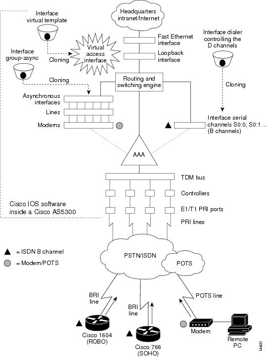
Different components inside Cisco IOS software work together to enable remote clients to dial in and send packets. Figure 1 shows one Cisco AS5300 access server that is receiving calls from a remote office, branch office (ROBO); small office, home office (SOHO); and modem client.
Depending on your network scenario, you may encounter all of the components in Figure 1. For example, you might decide to create a virtual IP subnet by using a loopback interface. This step saves address space. Virtual subnets can exist inside devices that you advertise to your backbone. In turn, IP packets get relayed to remote PCs, which route back to the central site.
Figure 1 Cisco IOS Dial Universe
Logical Constructs
A logical construct stores core protocol characteristics to assign to physical interfaces. No data packets are forwarded to a logical construct. Cisco uses three types of logical constructs in its access servers and routers. These constructs are described in the following sections:
•
Asynchronous Interfaces
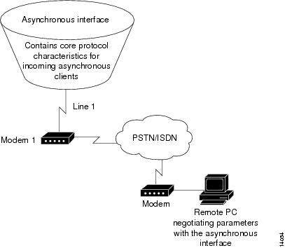
An asynchronous interface assigns network protocol characteristics to remote asynchronous clients that are dialing in through physical terminal lines and modems. (See Figure 2.)
Use the interface async command to create and configure an asynchronous interface.
Figure 2 Logical Construct for an Asynchronous Interface
To enable clients to dial in, you must configure two asynchronous components: asynchronous lines and asynchronous interfaces. Asynchronous interfaces correspond to physical terminal lines. For example, asynchronous interface 1 corresponds to tty line 1.
Commands entered in asynchronous interface mode configure protocol-specific parameters for asynchronous interfaces, whereas commands entered in line configuration configure the physical aspects for the same port.
Specifically, you configure asynchronous interfaces to support PPP connections. An asynchronous interface on an access server or router can be configured to support the following functions:
•
•
•
•
•
•
Group Asynchronous Interfaces
A group asynchronous interface is a parent interface that stores core protocol characteristics and projects them to a specified range of asynchronous interfaces. Asynchronous interfaces clone protocol information from group asynchronous interfaces. No data packets arrive in a group asynchronous interface. By setting up a group asynchronous interface, you also eliminate the need to repeatedly configure identical configuration information across several asynchronous interfaces.
Virtual Template Interfaces
A virtual template interface stores protocol configuration information for virtual access interfaces and protocol translation sessions. (See Figure 3.)
Figure 3 Logical Construct for a Virtual Template Interface
Templates for Virtual Access Interfaces
Virtual templates project configuration information to temporary virtual access interfaces triggered by multilink or virtual private dial-up network (VPDN) session events. When a virtual access interface is triggered, the configuration attributes in the virtual template are cloned and the negotiated parameters are applied to the connection.
The following example shows a virtual template interface on a Cisco 7206 router, which is used as a home gateway in a VPDN scenario:
Router# configure terminalRouter(config)# interface virtual-template 1Router(config-if)# ip unnumbered ethernet 2/1Router(config-if)# peer default ip address pool cisco-poolRouter(config-if)# ppp authentication chap papRouter(config-if)# exitRouter(config)# vpdn enableRouter(config)# vpdn incoming isp cisco.com virtual-template 1Templates for Protocol Translation
Virtual templates are used to simplify the process of configuring protocol translation to tunnel PPP or Serial Line Internet Protocol (SLIP) across X.25, TCP, and LAT networks. You can create a virtual interface template using the interface virtual-template command, and you can use it for one-step and two-step protocol translation. When a user dials in through a vty line and a tunnel connection is established, the router clones the attributes of the virtual interface template onto a virtual access interface. This virtual access interface is a temporary interface that supports the protocol configuration specified in the virtual interface template. This virtual access interface is created dynamically and lasts only as long as the tunnel session is active.
The virtual template in the following example explicitly specifies PPP encapsulation. The translation is from X.25 to PPP, which enables tunneling of PPP across an X.25 network.
Router# configure terminalRouter(config)# interface virtual-template 1Router(config-if)# ip unnumbered ethernet 0Router(config-if)# peer default ip address 172.18.2.131Router(config-if)# encapsulation pppRouter(config-if)# exitRouter(config)# translate x25 5555678 virtual-template 1For more information, refer to the chapter "Configuring Protocol Translation and Virtual Asynchronous Devices" in the Cisco IOS Terminal Services Configuration Guide.
Logical Interfaces
A logical interface receives and sends data packets and controls physical interfaces. Cisco IOS software provides three logical interfaces used for dial access. These interfaces are described in the following sections:
•
Dialer Interfaces
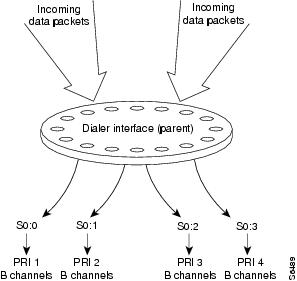
A dialer interface is a parent interface that stores and projects protocol configuration information that is common to all data (D) channels that are members of a dialer rotary group. Data packets pass through dialer interfaces, which in turn initiate dialing for inbound calls. In most cases, D channels get their core protocol intelligence from dialer interfaces.
Figure 4 shows packets coming into a dialer interface, which contains the configuration parameters common to four D channels (shown as S0:0, S0:1, S0:2, and S0:3). All the D channels are members of the same rotary group. Without the dialer interface configuration, each D channel must be manually configured with identical properties. Dialer interfaces condense and streamline the configuration process.
Figure 4 Dialer Interface and Its Neighboring Components
A dialer interface is user configurable and linked to individual B channels, where it delivers data packets to their physical destinations. Dialer interfaces seize physical interfaces to cause packet delivery. If a dialer interface engages in a multilink session, a dialer interface is in control of a virtual access interface, which in turn controls S0:3 or chassis 2 S0:3, for example. A dialer interface is created with the interface dialer global configuration command.
The following example shows a fully configured dialer interface:
Router# configure terminalRouter(config)# interface dialer 0Router(config-if)# ip unnumbered loopback 0Router(config-if)# no ip mroute-cacheRouter(config-if)# encapsulation pppRouter(config-if)# peer default ip address pool dialin_poolRouter(config-if)# dialer in-bandRouter(config-if)# dialer-group 1Router(config-if)# no fair-queueRouter(config-if)# no cdp enableRouter(config-if)# ppp authentication chap pap callinRouter(config-if)# ppp multilinkAll the D channels are members of rotary group 1.
Virtual Access Interfaces
A virtual access interface is a temporary interface that is spawned to terminate incoming PPP streams that have no physical connections. PPP streams, Layer 2 Forwarding Protocol (L2F), and Layer 2 Tunnel Protocol (L2TP) frames that come in on multiple B channels are reassembled on virtual access interfaces. These access interfaces are constructs used to terminate packets.
Virtual access interfaces obtain their set of instructions from virtual interface templates. The attributes configured in virtual templates are projected or cloned to a virtual access interfaces. Virtual access interfaces are not directly user configurable. These interfaces are created dynamically and last only as long as the tunnels or multilink sessions are active. After the sessions end, the virtual access interfaces disappear.
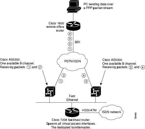
Figure 5 shows how a virtual access interface functions to accommodate a multilink session event. Two physical interfaces on two different access servers are participating in one multilink call from a remote PC. However, each Cisco AS5300 access server has only one B channel available to receive a call. All other channels are busy. Therefore all four packets are equally dispersed across two separate B channels and two access servers. Each Cisco AS5300 access server receives only half the total packets. A virtual access interface is dynamically spawned upstream on a Cisco 7206 backhaul router to receive the multilink protocol, track the multilink frames, and reassemble the packets. The Cisco 7206 router is configured to be the bundle master, which performs all packet assembly and reassembly for both Cisco AS5300 access servers.
Figure 5 Virtual Access Interfaces Used for Multichassis Multilink Session Events
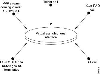
Virtual Asynchronous Interfaces
A virtual asynchronous interface is created on demand to support calls that enter the router through a nonphysical interface. For example, asynchronous character stream calls terminate or land on nonphysical interfaces. These types of calls include inbound Telnet, LAT, PPP over character-oriented protocols (such as V.120 or X.25), and LAPB-TA and PAD calls. A virtual asynchronous interface is also used to terminate L2F/L2TP tunnels, which are often traveling companions with Multilink protocol sessions. Virtual asynchronous interfaces are not user configurable; rather, they are dynamically created and torn down on demand. A virtual asynchronous line is used to access a virtual asynchronous interface.
Figure 6 shows a variety of calls that are terminating on a virtual asynchronous interface. After the calls end, the interface is torn down.
Figure 6 Asynchronous Character Stream Calls Terminating on a Virtual Asynchronous Interface
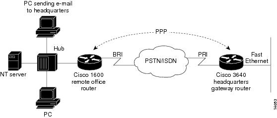
Circuit-Switched Digital Calls
Circuit-switched digital calls are usually ISDN 56-kbps or 64-kbps data calls that use PPP. These calls are initiated by an ISDN router, access server, or terminal adapter that is connected to a client workstation. Individual synchronous serial digital signal level 0 (DS0) bearer (B) channels are used to transport circuit-switched digital calls across WANs. These calls do not transmit across "old world" lines.
Figure 7 shows a Cisco 1600 series remote office router dialing in to a Cisco 3640 router positioned at a headquarters gateway.
Figure 7 Remote Office LAN Dialing In to Headquarters
T1 and E1 Controllers
Cisco controllers negotiate the following parameters between an access server and a central office: line coding, framing, clocking, DS0/time-slot provisioning, and signaling.
Time slots are provisioned to meet the needs of particular network scenarios. T1 controllers have
24 time slots, and E1 controllers have 30 time slots. To support traffic flow for one ISDN PRI line in a T1 configuration, use the pri-group command. To support traffic flow for analog calls over a channelized E1 line with recEive and transMit (E&M—also ear and mouth) signaling, use the cas-group 1 timeslots 1-30 type e&m-fgb command. Most telephone companies do not support provisioning one trunk for different combinations of time-slot services, though this provisioning is supported on Cisco controllers. On a T1 controller, for example, time slots 1 to 10 could run PRI, time slots 11 to 20 could run channel-associated signaling (CAS), and time slots 21 to 24 could support leased-line grouping.The following example configures one of four T1 controllers on a Cisco AS5300 access server:
Router# configure terminalRouter(config)# controller t1 ?<0-3> Controller unit numberRouter(config)# controller t1 0Router(config-controller)# framing esfRouter(config-controller)# linecode b8zsRouter(config-controller)# clock source line primaryRouter(config-controller)# pri-group timeslots 1-24Router(config-controller)#This example supports modem calls and circuit-switched digital calls over ISDN PRI.
Non-ISDN Channelized T1 and Channelized E1 Lines
A channelized T1 or channelized E1 line is an analog line that was originally intended to support analog voice calls, but has evolved to support analog data calls. ISDN is not sent across channelized T1 or E1 lines. Channelized T1 and channelized E1 lines are often referred to as CT1 and CE1. These channelized lines are found in "old world," non-ISDN telephone networks.
The difference between traditional channelized lines (analog) and nonchannelized lines (ISDN) is that channelized lines have no built-in D channel. That is, all 24 channels on a T1 line carry only data. The signaling is in-band or associated to the data channels. Traditional channelized lines do not support digitized data calls (for example, BRI with 2B + D). Channelized lines support a variety of in-band signal types, such as ground start, loop start, wink start, immediate start, E&M, and R2.
Signaling for channelized lines is configured with the cas-group controller configuration command. The following example configures E&M group B signaling on a T1 controller:
Router# configure terminalRouter(config)# controller t1 0Router(config-controller)# cas-group 1 timeslots 1-24 type ?e&m-fgb E & M Type II FGBe&m-fgd E & M Type II FGDe&m-immediate-start E & M Immediate Startfxs-ground-start FXS Ground Startfxs-loop-start FXS Loop Startr1-modified R1 Modifiedsas-ground-start SAS Ground Startsas-loop-start SAS Loop StartRouter(config-controller)# cas-group 1 timeslots 1-24 type e&m-fgbRouter(config-controller)# framing esfRouter(config-controller)# clock source line primaryISDN Service
Cisco routing devices support ISDN BRI and ISDN PRI. Both media types use B channels and D channels. Figure 8 shows how many B channels and D channels are assigned to each media type.
Figure 8 Logical Relationship of B Channels and D Channels
ISDN BRI
ISDN BRI operates over most of the copper twisted-pair telephone wiring in place. ISDN BRI delivers a total bandwidth of a 144 kbps via three separate channels. Two of the B channels operate at 64 kbps and are used to carry voice, video, or data traffic. The third channel, the D channel, is a 16-kbps signaling channel used to tell the Public Switched Telephone Network (PSTN) how to handle each of the B channels. ISDN BRI is often referred to as "2 B + D."
Enter the interface bri command to bring up and configure a single BRI interface, which is the overseer of the 2 B + D channels. The D channel is not user configurable.
The following example configures an ISDN BRI interface on a Cisco 1600 series router. The isdn spid command defines the service profile identifier (SPID) number for both B channels. The SPID number is assigned by the ISDN service provider. Not all ISDN lines have SPIDs.
Router# configure terminalRouter(config)# interface bri 0Router(config-if)# isdn spid1 55598760101Router(config-if)# isdn spid2 55598770101Router(config-if)# isdn switch-type basic-niRouter(config-if)# ip unnumbered ethernet 0Router(config-if)# dialer map ip 172.168.37.40 name hq 5552053Router(config-if)# dialer load-threshold 70Router(config-if)# dialer-group 1Router(config-if)# encapsulation pppRouter(config-if)# ppp authentication chap pap callinRouter(config-if)# ppp multilinkRouter(config-if)# no shutdownISDN PRI
ISDN PRI is designed to carry large numbers of incoming ISDN calls at point of presences (POPs) and other large central site locations. All the reliability and performance of ISDN BRI applies to ISDN PRI, but ISDN PRI has 23 B channels running at 64 kbps each and a shared 64 kbps D channel that carries signaling traffic. ISDN PRI is often referred to as "23 B + D" (North America and Japan) or "30 B + D" (rest of the world).
The D channel notifies the central office switch to send the incoming call to particular timeslots on the Cisco access server or router. Each one of the B channels carries data or voice. The D channel carries signaling for the B channels. The D channel identifies if the call is a circuit-switched digital call or an analog modem call. Analog modem calls are decoded and then sent to the onboard modems. Circuit-switched digital calls are directly relayed to the ISDN processor in the router. Enter the interface serial command to bring up and configure the D channel, which is user configurable.
Figure 9 shows the logical contents of an ISDN PRI interface used in a T1 network configuration. The logical contents include 23 B channels, 1 D channel, 24 time slots, and 24 virtual serial interfaces (total number of B + D channels).
Figure 9 Logical Relationship of ISDN PRI Components for T1
The following example is for a Cisco AS5300 access server. It configures one T1 controller for ISDN PRI, then configures the neighboring D channel (interface serial 0:23). Controller T1 0 and interface serial 0:23 are both assigned to the first PRI port. The second PRI port is assigned to controller T1 1 and interface serial 1:23, and so on. The second PRI port configuration is not shown in this example. This Cisco AS5300 access server is used as part of a stack group dial-in solution for an Internet service provider.
Router# configure terminalRouter(config)# controller t1 0Router(config-controller)# framing esfRouter(config-controller)# linecode b8zsRouter(config-controller)# clock source line primaryRouter(config-controller)# pri-group timeslots 1-24Router(config-controller)# exitRouter(config)# interface serial 0:23Router(config-if)# ip unnumbered Loopback 0Router(config-if)# ip accounting output-packetsRouter(config-if)# no ip mroute-cacheRouter(config-if)# encapsulation pppRouter(config-if)# isdn incoming-voice modemRouter(config-if)# dialer-group 1Router(config-if)# no fair-queueRouter(config-if)# compress stacRouter(config-if)# no cdp enableRouter(config-if)# ppp authentication chapRouter(config-if)# ppp multilinkRouter(config-if)# netbios nbfLine Types
This section describes the different line types used for dial access. It also describes the relationship between lines and interfaces.
Note
Table 1 shows the types of lines that can be configured.
Table 1 Available Line Types
CON or CTY
Console
Typically used to log in to the router for configuration purposes.
Line 0.
AUX
Auxiliary
EIA/TIA-232 data terminal equipment (DTE) port used as a backup (tty) asynchronous port. Cannot be used as a second console port.
Last tty line number plus 1.
tty
Asynchronous
Same as asynchronous interface. Used typically for remote-node dial-in sessions that use such protocols as SLIP, PPP, AppleTalk Remote Access (ARA), and XRemote.
The numbering widely varies between platforms. This number is equivalent to the maximum number of modems or asynchronous interfaces supported by your access server or router.1
vty
Virtual asynchronous
Used for incoming Telnet, LAT, X.25 PAD, and protocol translation connections into synchronous ports (such as Ethernet and serial interfaces) on the router.
Last tty line number plus 2 through the maximum number of vty lines specified.2
1 Enter the interface line tty ? command to view the maximum number of tty lines supported.
2 Increase the number of vty lines on a router using the line vty global configuration command. Delete vty lines with the no line vty line-number command. The line vty command accepts any line number larger than 5 up to the maximum number of lines supported by your router with its current configuration. Enter the interface line vty ? command to view the maximum number of vty lines supported.
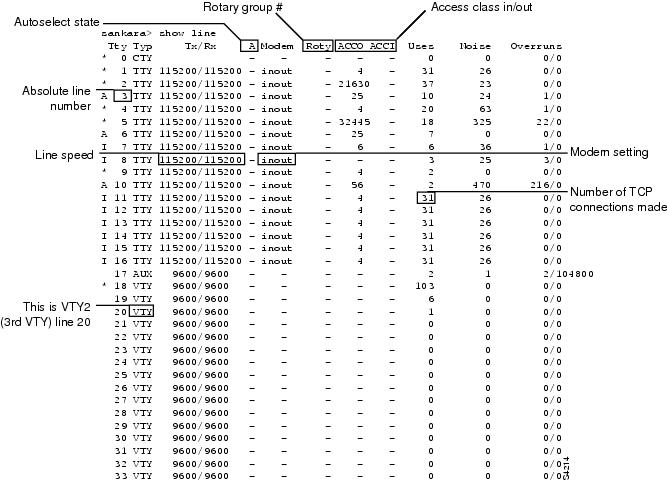
Use the show line command to see the status of each of the lines available on a router. (See Figure 10.)
Figure 10 Sample Show Line Output Showing CTY, tty, AUX, and vty Line Statistics
Relationship Between Lines and Interfaces
The following sections describe the relationship between lines and interfaces:
•
•
Asynchronous Interfaces and Physical Terminal Lines
Asynchronous interfaces correspond to physical terminal lines. Commands entered in asynchronous interface mode let you configure protocol-specific parameters for asynchronous interfaces; commands entered in line configuration mode let you configure the physical aspects of the line port.
For example, to enable IP resources to dial in to a network through a Cisco 2500 series access server, configure the lines and asynchronous interfaces as follows.
•
line 1 16login localmodem inoutspeed 115200flowcontrol hardware! Configures the line to autosense PPP; physical line attribute.autoselect ppp•
interface async 1encapsulation pppasync mode interactiveasync dynamic addressasync dynamic routingasync default ip address 192.168.16.132ppp authentication chapThe remote node services SLIP, PPP, and XRemote are configured in asynchronous interface mode. ARA is configured in line configuration mode on virtual terminal lines or physical terminal lines.
Synchronous Interfaces and Virtual Terminal Lines
Virtual terminal lines provide access to the router through a synchronous interface. Virtual terminal lines do not correspond to synchronous interfaces in the same way that physical terminal lines correspond to asynchronous interfaces because vty lines are created dynamically on the router, whereas physical terminal lines are static physical ports. When a user connects to the router on a vty line, that user is connecting into a virtual port on an interface. You can have multiple virtual ports for each synchronous interface.
For example, several Telnet connections can be made to an interface (such as an Ethernet or serial interface).
The number of virtual terminal lines available on a router is defined using the line vty number-of-lines global configuration command.
Encapsulation Types
Synchronous serial interfaces default to High-Level Data Link Control (HDLC) encapsulation, and asynchronous serial interfaces default to SLIP encapsulation. Cisco IOS software provides a long list of encapsulation methods that can be set on the interface to change the default encapsulation method. See the Cisco IOS Interface Command Reference for a complete list and description of these encapsulation methods.
The following list summarizes the encapsulation commands available for serial interfaces used in dial configurations:
•
•
•
•
•
To use SLIP or PPP encapsulation, the router or access server must be configured with an IP routing protocol.
Cisco and the Cisco Logo are trademarks of Cisco Systems, Inc. and/or its affiliates in the U.S. and other countries. A listing of Cisco's trademarks can be found at www.cisco.com/go/trademarks. Third party trademarks mentioned are the property of their respective owners. The use of the word partner does not imply a partnership relationship between Cisco and any other company. (1005R)
Any Internet Protocol (IP) addresses and phone numbers used in this document are not intended to be actual addresses and phone numbers. Any examples, command display output, network topology diagrams, and other figures included in the document are shown for illustrative purposes only. Any use of actual IP addresses or phone numbers in illustrative content is unintentional and coincidental.
© 2007-2009 Cisco Systems, Inc. All rights reserved.