-
Dial Technologies Configuration Guide, Cisco IOS Release 15.2S
- Part 1: Dial Interfaces, Controllers, and Lines
-
Part 2 - Modem Configuration and Management
-
Overview of Modem Interfaces
-
Configuring and Managing Integrated Modems
-
1- and 2-Port V.90 Modem WICs for Cisco 2600 and Cisco 3600 Series Multiservice Platforms
-
Call Tracker show Commands Extensions
-
Cisco NM-8AM-V2 and NM-16AM-V2 Analog Modem Network Modules with V.92
-
MICA and NextPort Modem Tech-Support Command Additions
-
PIAFS Wireless Data Protocol Version 2.1 for Cisco MICA Modems
-
V.92 and V.44 Support for Digital Modems
-
V.92 Modem on Hold for Cisco AS5300 and Cisco AS5800 Universal Access Servers
-
V.92 Modem on Hold for Cisco AS5350, Cisco AS5400, and Cisco AS5850 Universal Gateways and Cisco AS5800 Universal Access Servers
-
V.92 Quick Connect for Cisco AS5300 and Cisco AS5800 Universal Access Servers
-
V.92 Quick Connect for Cisco AS5350, Cisco AS5400, and Cisco AS5850 Universal Gateways and Cisco AS5800 Universal Access Servers
-
V.92 Reporting Using RADIUS Attribute v.92-info
-
Configuring and Managing Cisco Access Servers and Dial Shelves
-
Configuring and Managing External Modems
-
Modem Signal and Line States
-
Creating and Using Modem Chat Scripts
-
Cisco Modem User Interface
-
Modem Script and System Script Support in Large-Scale Dial-Out
-
- Part 3 - ISDN Configuration
- Part 4 - Signaling Configuration
-
Part 5 - Dial-on-Demand Routing Configuration
-
Preparing to Configure DDR
-
Configuring Legacy DDR Spokes
-
Configuring Legacy DDR Hubs
-
Configuring Peer-to-Peer DDR with Dialer Profiles
-
Dialer Map VRF-Aware for an MPLS VPN
-
Dialer Persistent
-
PPPoE Client DDR Idle-Timer
-
Redial Enhancements
-
Rotating Through Dial Strings
-
Configuring Dialer CEF
-
CEF Support for Dialer Profiles on Cisco 7500 Routers
-
Configuring Snapshot Routing
-
- Part 6: Dial-Backup Configuration
- Part 7: Dial-Related Addressing Services
- Part 8: Virtual Templates and Profiles
-
Part 9: PPP Configuration
-
Configuring Asynchronous SLIP and PPP
-
Optimized PPP Negotiation
-
Customer Profile Idle Timer Enhancements for Interesting Traffic
-
Multiclass Multilink PPP
-
Configuring Media-Independent PPP and Multilink PPP
-
PPP/MLP MRRU Negotiation Configuration
-
Troubleshooting Enhancements for Multilink PPP over ATM Link Fragmentation and Interleaving
-
Multichassis Multilink PPP
-
- Part 10: Callback and Bandwidth Allocation Configuration
- Part 11: Dial Access Specialized Features
- Appendix
 Feedback
Table Of Contents
DDR Hubs Configuration Task Flow
Configuring the Interface to Place Calls Only
Defining the Dialing Destination
Specifying a Physical Interface to Use and Assigning It to a Dialer Rotary Group
Configuring the Interface to Receive Calls Only
Configuring the Interface for TACACS+
Configuring the Interface for PPP Authentication
Specifying Physical Interfaces and Assigning Them to the Dialer Rotary Group
Configuring the Interface to Place and Receive Calls
Defining One or More Dialing Destinations
Defining the Traffic to Be Authenticated
Configuring Access Control for Outgoing Calls
Configuring Access Control for Bridging
Configuring Access Control for Routing
Customizing the Interface Settings
Configuring Timers on the DDR Interface
Setting Dialer Interface Priority
Configuring a Dialer Hold Queue
Configuring Bandwidth on Demand
Disabling and Reenabling DDR Fast Switching
Configuring Dialer Redial Options
Sending Traffic over Frame Relay, X.25, or LAPB Networks
Configuring the Interface for Sending Traffic over a Frame Relay Network
Configuring the Interface for Sending Traffic over an X.25 Network
Configuring the Interface for Sending Traffic over a LAPB Network
Configuration Examples for Legacy DDR Hub
Transparent Bridging over DDR Examples
DDR Configuration in an IP Environment Example
AppleTalk Configuration Example
Banyan VINES Configuration Example
ISO CLNS Configuration Example
Hub-and-Spoke DDR for Asynchronous Interfaces and Authentication Example
Single Site or Multiple Sites Dialing Configuration Example
Multiple Destinations Configuration Example
Dialer Interfaces and Dialer Rotary Groups Example
DDR Configuration Using Dialer Interface and PPP Encapsulation Example
Two-Way DDR with Authentication Example
Frame Relay Access with In-Band Dialing and Static Mapping
Frame Relay Access with ISDN Dialing and DDR Dynamic Maps
Frame Relay Access with ISDN Dialing and Subinterfaces
X.25 Support Configuration Example
LAPB Support Configuration Example
Configuring Legacy DDR Hubs
This chapter describes how to configure legacy dial-on-demand routing (DDR) on interfaces functioning as the hub in a hub-and-spoke network topology. It includes the following main sections:
•
DDR Hubs Configuration Task Flow
•
This chapter considers a hub interface to be any interface that calls or receives calls from more than one other router and considers a spoke interface to be an interface that calls or receives calls from exactly one router.
For configuration tasks for the spoke interfaces in a hub-and-spoke network topology, see the chapter "Configuring Legacy DDR Spokes" in this publication.
For information about the dialer profiles implementation of DDR, see the chapter "Configuring Peer-to-Peer DDR with Dialer Profiles" in this publication.
To identify the hardware platform or software image information associated with a feature, use the Feature Navigator on Cisco.com to search for information about the feature or refer to the software release notes for a specific release. For more information, see the "Identifying Supported Platforms" section in the "Using Cisco IOS Software" chapter.
For a complete description of the DDR commands in this chapter, see the Cisco IOS Dial Technologies Command Reference, Release 12.2. To locate documentation of other commands that appear in this chapter, use the command reference master index or search online.
DDR Issues
A DDR configuration applies to a specified router interface but serves to meet the communication needs of the network. The router configured for DDR has a function to serve in preserving communications and ensuring that routes are known to other routers at both ends of the dial link. Thus, these issues are important:
•
•
•
•
•
•
•
DDR Hubs Configuration Task Flow
Before you configure DDR, make sure you have completed the preparations for bridging or routing as described in the chapter "Preparing to Configure DDR" in this publication. That chapter provides information about the minimal requirements. For detailed information about bridging, routing, and wide-area networking configurations, see the appropriate chapters in other volumes of this documentation set.
When you configure DDR on a hub interface in a hub-and-spoke topology, you perform the following general steps:
Step 1
Step 2
Step 3
Step 4
Step 5
Step 6
•
or
•
Step 7
When you have configured the interface and it is operational, you can monitor its performance and its connections as described in the "Monitoring DDR Connections" section later in this chapter.
You can also enhance DDR by configuring Multilink PPP and configuring PPP callback. The PPP configuration tasks are described in the chapter "Configuring Media-Independent PPP and Multilink PPP" in this publication.
See the section "Configuration Examples for Legacy DDR Hub" at the end of this chapter for examples of how to configure DDR on your network.
How to Configure DDR
To configure DDR on an interface, perform the tasks in the following sections. The first five bulleted items are required. The remaining tasks are not absolutely required, but might be necessary in your networking environment.
•
•
•
or
Configuring the Interface to Receive Calls Only (Required)
or
Configuring the Interface to Place and Receive Calls (Required)•
•
•
See the section "Monitoring DDR Connections" later in this chapter for commands and other information about monitoring DDR connections. See the section "Configuration Examples for Legacy DDR Hub" at the end of this chapter for ideas about how to implement DDR in your network.
Specifying the Interface
You can configure any asynchronous, synchronous serial, ISDN, or dialer interface for legacy DDR.
Note
To specify an interface to configure for DDR, use one of the following commands in global configuration mode:
Dialer interfaces are logical or virtual entities, but they use physical interfaces to place or receive calls.
Enabling DDR on the Interface
This task is required for asynchronous serial, synchronous serial, and logical dialer interfaces.
This task is not required for ISDN interfaces (BRI interfaces and ISDN PRI D channels) and for purely passive interfaces that will receive calls only from interfaces that use DTR dialing.
Enabling DDR on an interface usually requires you to specify the type of dialer to be used. This task is not required for ISDN interfaces because the software automatically configures ISDN interfaces to be dialer type ISDN.
To enable DDR on the interface, use the following command in interface configuration mode:
Router(config-if)# dialer in-band [no-parity | odd-parity]
Enables DDR on an asynchronous interface or a synchronous serial interface using V.25bis modems.
You can optionally specify parity if the modem on this interface uses the V.25bis command set. The 1984 version of the V.25bis specification states that characters must have odd parity. However, the default for the dialer in-band command is no parity.
Configuring the Interface to Place Calls Only
To configure an interface to place calls to multiple destinations, perform the following tasks. The first task is required for all interface types. The second task is required only if you specified a dialer interface.
•
•
Defining the Dialing Destination
For calling multiple sites, an interface or dialer rotary group must be configured to map each next hop protocol address to the dial string (some form of a telephone number) used to reach it.
To define each dialing destination, use one of the following commands in interface configuration mode:
Repeat this task as many times as needed to ensure that all dialing destinations are reachable via some next hop address and dialed number.
If you intend to send traffic over other types of networks, see one of the following sections later in this chapter: "Configuring the Interface for Sending Traffic over a Frame Relay Network," "Configuring the Interface for Sending Traffic over an X.25 Network," or "Configuring the Interface for Sending Traffic over a LAPB Network."
Specifying a Physical Interface to Use and Assigning It to a Dialer Rotary Group
This section applies only if you specified a dialer interface to configure for DDR.
To assign a physical interface to a dialer rotary group, use the following commands beginning in global configuration mode:
Repeat these two steps for each physical interface to be used by the dialer interface.
An ISDN BRI is a rotary group of B channels. An ISDN interface can be part of a rotary group comprising other interfaces (synchronous, asynchronous, ISDN BRI, or ISDN PRI). However, Cisco supports at most one level of recursion; that is, a rotary of rotaries is acceptable, but a rotary of rotaries of rotaries is not supported.
Interfaces in a dialer rotary group do not have individual addresses; when the interface is being used for dialing, it inherits the parameters configured for the dialer interface. However, if the individual interface is configured with an address and it is subsequently used to establish a connection from the user EXEC level, the individual interface address again applies.
Note
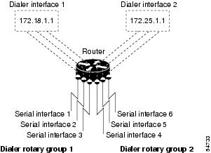
Figure 1 illustrates how dialer interfaces work. In this configuration, serial interfaces 1, 2, and 3 are assigned to dialer rotary group 1 and thereby take on the parameters configured for dialer interface 1. When it is used for dialing, the IP address of serial interface 2 is the same as the address of the dialer interface, 172.18.1.1.
Figure 1 Sample Dialer Interface Configuration
Configuring the Interface to Receive Calls Only
Once DDR is enabled on an asynchronous serial, synchronous serial, and ISDN interface, the interface can receive calls from multiple sites using one line or multiple lines. However, interfaces that receive calls from multiple sites require authentication of the remote sites. In addition, dialer interfaces require at least one physical interface to be specified and added to the dialer rotary group. The tasks in the following sections describe how to configuration authentication:
•
or
•
•
Configuring the Interface for TACACS+
To configure TACACS as an alternative to host authentication, use one of the following commands in interface configuration mode:
Router(config-if)# ppp use-tacacs [single-line]
or
Router(config-if)# aaa authentication ppp
Configures TACACS.
Use the ppp use-tacacs command with TACACS and extended TACACS. Use the aaa authentication ppp command with authentication, authorization, and accounting (AAA)/TACACS+.
Configuring the Interface for PPP Authentication
This section specifies the minimum required configuration for PPP Challenge Handshake Authentication Protocol (CHAP) or Password Authentication Protocol (PAP) authentication. For more detailed information, see the chapter "Configuring Media-Independent PPP and Multilink PPP" in this publication.
To use CHAP or PAP authentication, perform the following steps beginning in interface configuration mode:
Note
1.
2.
To enable PPP encapsulation, use the following commands beginning in interface configuration mode:
Specifying Physical Interfaces and Assigning Them to the Dialer Rotary Group
To assign a physical interface to a dialer rotary group, use the following commands beginning in global configuration mode:
Repeat these two steps for each physical interface to be used by the dialer interface.
Configuring the Interface to Place and Receive Calls
You can configure an physical interface or dialer interface to both place and receive calls. For placing calls, the interface must be configured to map each next hop address to the telephone number to dial. For receiving calls from multiple sites, the interface must be configured to authenticate callers.
Figure 2 shows a configuration in which the central site is calling and receiving calls from multiple sites. In this configuration, multiple sites are calling in to a central site, and the central site might be calling one or more of the remote sites.
Figure 2 Hub-and-Spoke Configuration Using DDR
To configure a single line, multiple lines, or a dialer interface to place calls to and receive calls from multiple sites, perform the tasks in the following section:
•
•
If you intend to send traffic over other types of networks, see one of the following sections later in this chapter: "Configuring the Interface for Sending Traffic over a Frame Relay Network," "Configuring the Interface for Sending Traffic over an X.25 Network," or "Configuring the Interface for Sending Traffic over a LAPB Network."
Defining One or More Dialing Destinations
For calling multiple sites, an interface or dialer rotary group must be configured to map each next hop protocol address to the dial string (some form of a telephone number) used to reach it.
To define each dialing destination, use one of the following commands in interface configuration mode:
Repeat this task as many times as needed to ensure that all dialing destinations are reachable via some next hop address and dialed number.
Defining the Traffic to Be Authenticated
Calls from the multiple sites must be authenticated. Authentication can be done through CHAP or PAP. In addition, the interface must be configured to map the protocol address of a host to the name to use for authenticating the remote host.
To enable CHAP or PAP on an interface and authenticate sites that are calling in, use the following commands in interface configuration mode:
If the dial string is not used, the interface will be able to receive calls from the host, but will not be able to place calls to the host.
Repeat this task for each site from which the router will receive calls.
Configuring Access Control for Outgoing Calls
Protocol access lists and dialer access lists are central to the operation of DDR. In general, access lists are used as the screening criteria for determining when to initiate DDR calls. All packets are tested against the dialer access list. Packets that match a permit entry are deemed interesting or packets of interest. Packets that do not match a permit entry or that do match a deny entry are deemed uninteresting. When a packet is found to be interesting, either the dialer idle timer is reset (if the line is active) or a connection is attempted (assuming the line is available but not active). If a tested packet is deemed uninteresting, it will be forwarded if it is intended for a destination known to be on a specific interface and the link is active. However, such a packet will not initiate a DDR call and will not reset the idle timer.
Configuring Access Control for Bridging
When you completed preparations for bridging over DDR, you entered global access lists to specify the protocol packets to be permitted or denied, and global dialer lists to specify which access list to use and which dialer group will place the outgoing calls.
Now you must tie those global lists to an interface configured for DDR. You do this by assigning selected interfaces to a bridge group. Because packets are bridged only among interfaces that belong to the same bridge group, you need to assign this interface and others to the same bridge group.
To assign an interface to a bridge group, use the following command in interface configuration mode:
Router(config-if)# bridge-group bridge-group
Assigns the specified interface to a bridge group.
For examples of bridging over DDR, see the "Transparent Bridging over DDR Examples" section later in this chapter.
Configuring Access Control for Routing
Before you perform the tasks outlined in this section, you should have completed the preparations for routing a protocol over DDR as described briefly in the chapter "Preparing to Configure DDR" in this publication and as described in greater detail in the appropriate network protocols configuration guide (for example, the Cisco IOS AppleTalk and Novell IPX Configuration Guide).
An interface can be associated only with a single dialer access group; multiple dialer access group assignments are not allowed. To specify the dialer access group to which you want to assign an access list, use the following command in interface configuration mode:
Router(config-if)# dialer-group group-number
Specifies the number of the dialer access group to which the specific interface belongs.
Customizing the Interface Settings
To customize DDR in your network, perform the tasks in the following sections as needed:
•
•
•
•
•
•
Configuring Timers on the DDR Interface
To configure DDR interface timers, perform the tasks in the following sections as needed:
•
•
•
•
Setting Line-Idle Time
To specify the amount of time for which a line will stay idle before it is disconnected, use the following command in interface configuration mode:
Setting Idle Time for Busy Interfaces
The dialer fast idle timer is activated if there is contention for a line. Contention occurs when a line is in use, a packet for a different next hop address is received, and the busy line is required to send the competing packet.
If the line has been idle for the configured amount of time, the current call is disconnected immediately and the new call is placed. If the line has not yet been idle as long as the fast idle timeout period, the packet is dropped because the destination is unreachable. (After the packet is dropped, the fast idle timer remains active and the current call is disconnected as soon as it has been idle for as long as the fast idle timeout). If, in the meantime, another packet is sent to the currently connected destination, and it is classified as interesting, the fast-idle timer is restarted.
To specify the amount of time for which a line for which there is contention will stay idle before the line is disconnected and the competing call is placed, use the following command in interface configuration mode:
This command applies to both inbound and outbound calls.
Setting Line-Down Time
To set the length of time for which the interface stays down before it is available to dial again after a line is disconnected or fails, use the following command in interface configuration mode:
This command applies to both inbound and outbound calls.
Setting Carrier-Wait Time
To set the length of time for which an interface waits for the telephone service (carrier), use the following command in interface configuration mode:
Router(config-if)# dialer wait-for-carrier-time seconds
Sets the length of for which time the interface waits for the carrier to come up when a call is placed.
For asynchronous interfaces, this command sets the total time to wait for a call to connect. This time is set to allow for running the chat script.
Setting Dialer Interface Priority
You can assign dialer priority to an interface. Priority indicates which interface in a dialer rotary group will get used first. To assign priority to a dialer interface, use the following command in interface configuration mode:
Router(config-if)# dialer priority number
Specifies which dialer interfaces will be used first.
For example, you might give one interface in a dialer rotary group higher priority than another if it is attached to a faster, more reliable modem. In this way, the higher-priority interface will be used as often as possible.
The range of values for number is 0 through 255. Zero is the default value and lowest priority; 255 is the highest priority. This command applies to outgoing calls only.
Configuring a Dialer Hold Queue
Sometimes packets destined for a remote router are discarded because no connection exists. Establishing a connection using an analog modem can take time, during which packets are discarded. However, configuring a dialer hold queue will allow interesting outgoing packets to be queued and sent as soon as the modem connection is established.
A dialer hold queue can be configured on any type of dialer, including in-band synchronous, asynchronous, DTR, and ISDN dialers. Also, hunt group leaders can be configured with a dialer hold queue. If a hunt group leader (of a rotary dialing group) is configured with a hold queue, all members of the group will be configured with a dialer hold queue and no hold queue for an individual member can be altered.
To establish a dialer hold queue, use the following command in interface configuration mode:
Router(config-if)# dialer hold-queue packets
Creates a dialer hold queue and specifies the number of packets to be held in it.
As many as 100 packets can be held in an outgoing dialer hold queue.
Configuring Bandwidth on Demand
You can configure a dialer rotary group to use additional bandwidth by placing additional calls to a single destination if the load for the interface exceeds a specified weighted value. Parallel communication links are established based on traffic load. The number of parallel links that can be established to one location is not limited.
To set the dialer load threshold for bandwidth on demand, use the following command in interface configuration mode:
Router(config-if)# dialer load-threshold load
Configures the dialer rotary group to place additional calls to a destination, as indicated by interface load.
Once multiple links are established, they are still governed by the load threshold. If the total load falls below the threshold, an idle link will be torn down.
Disabling and Reenabling DDR Fast Switching
Fast switching is enabled by default on all DDR interfaces. When fast switching is enabled or disabled on an ISDN D channel, it is enabled or disabled on all B channels. When fast switching is enabled or disabled on a dialer interface, it is enabled or disabled on all rotary group members but cannot be enabled or disabled on the serial interfaces individually.
Fast switching can be disabled and re-enabled on a protocol-by-protocol basis. To disable fast switching and re-enable it, use one of the following protocol-specific commands in interface configuration mode:
Configuring Dialer Redial Options
By default, the Cisco IOS software generates a single dial attempt for each interesting packet. Dialer redial allows the dialer to be configured to make a maximum number of redial attempts if the first dial-out attempt fails, wait a specific interval between redial attempts, and disable the interface for a specified duration if all redial attempts fail. New dialout attempts will not be initiated if a redial is pending to the same destination.
To configure redial options, use the following commands beginning in global configuration mode:
Sending Traffic over Frame Relay, X.25, or LAPB Networks
An interface configured for DDR can send traffic over networks that require Link Access Procedure, Balanced (LAPB), X.25, or Frame Relay encapsulation.
Before Cisco IOS software Release 12.0(6)T, encapsulation techniques such as Frame Relay, High-Level Data Link Control (HDLC), LAPB-TA, and X.25 could support only one ISDN B-channel connection over the entire link. HDLC and PPP could support multiple B channels, but the entire ISDN link needed to use the same encapsulation. Dynamic multiple encapsulations allow incoming calls over ISDN to be assigned encapsulation type based on calling line identification (CLID) or Dialed Number Identification Service (DNIS). With dynamic multiple encapsulations, once CLID binding is completed, the topmost interface is always used for all configuration and data structures. The ISDN B channel becomes a forwarding device, and the configuration on the D channel is ignored, thereby allowing the different encapsulation types and per-user configurations.
To configure an interface for those networks, perform the tasks in the following sections:
•
•
•
Configuring the Interface for Sending Traffic over a Frame Relay Network
Access to Frame Relay networks is now available through dialup connections and leased lines. Dialup connectivity allows Frame Relay networks to be extended to sites that do not generate enough traffic to justify leased lines, and also allows a Frame Relay network to back up another network or point-to-point line.
DDR over Frame Relay is supported for synchronous serial and ISDN interfaces and for rotary groups, and is available for in-band, DTR, and ISDN dialers.
Frame Relay supports multiple permanent virtual circuit (PVC) connections over the same serial interface or ISDN B channel, but only one physical interface can be used (dialed, connected, and active) in a rotary group or with ISDN.
Dynamic multiple encapsulations support the following Frame Relay features:
•
•
•
•
Dynamic multiple encapsulations support at least four Frame Relay PVCs on either dialer interfaces or dialer subinterfaces.
Note
Configuration Restrictions
The following restrictions apply to DDR used over Frame Relay:
•
•
•
•
•
Note
Configuration Overview
No new commands are required to support DDR over Frame Relay. In general, you configure Frame Relay and configure DDR. In general, to configure an interface for DDR over Frame Relay, perform the following tasks:
•
•
For example, enter the IP address and mask, the IPX network number, and the AppleTalk cable range and zone.
•
As a minimum, you must enable Frame Relay encapsulation and decide whether you need to do static or dynamic address mapping. If you decide to do dynamic mapping, you need not enter a command because Inverse ARP is enabled by default. If you decide to do static mapping, you must enter Frame Relay mapping commands.
You can then configure various options as needed for your Frame Relay network topology.
•
At a minimum, you must decide and configure the interface for outgoing calls only, incoming calls only, or both outgoing and incoming calls.
You can also configure DDR for your routed protocols (as specified in the chapter "Preparing to Configure DDR") and for snapshot routing (as specified in the chapter "Configuring Snapshot Routing" later in this publication). You can also customize DDR on your router or access server (as described in the "Customizing the Interface Settings" section later in this chapter).
For examples of configuring various interfaces for DDR over Frame Relay, see the section "Frame Relay Support Examples" later in this chapter.
Configuring the Interface for Sending Traffic over an X.25 Network
X.25 interfaces can now be configured to support DDR. Synchronous serial and ISDN interfaces on Cisco routers and access servers can be configured for X.25 addresses, X.25 encapsulation, and mapping of protocol addresses to the X.25 address of a remote host. In-band, DTR, and ISDN dialers can be configured to support X.25 encapsulation, but rotary groups cannot.
Remember that for ISDN interfaces, once CLID binding is completed, the topmost interface is always used for all configuration and data structures. The ISDN B channel becomes a forwarding device, and the configuration on the D channel is ignored, thereby allowing the different encapsulation types and per-user configurations. For X.25 encapsulations, the configurations reside on the dialer profile. The Dynamic Multiple Encapsulations feature provides support for packet assembler/disassembler (PAD) traffic and X.25 encapsulated and switched packets.
To configure an interface to support X.25 and DDR, use the following X.25-specific commands in interface configuration mode:
The order of DDR and X.25 configuration tasks is not critical; you can configure DDR before or after X.25, and you can even mix the DDR and X.25 commands.
For an example of configuring an interface for X.25 encapsulation and then completing the DDR configuration, see the section "X.25 Support Configuration Example" later in this chapter.
Configuring the Interface for Sending Traffic over a LAPB Network
DDR over serial lines now supports LAPB encapsulation, in addition to the previously supported PPP, HDLC, and X.25 encapsulations.
LAPB encapsulation is supported on synchronous serial, ISDN, and dialer rotary group interfaces, but not on asynchronous dialers.
Because the default encapsulation is HDLC, you must explicitly configure LAPB encapsulation. To configure an interface to support LAPB encapsulation and DDR, use the following command in interface configuration mode:
Router(config-if)# encapsulation lapb [dte | dce] [multi | protocol]
Specifies LAPB encapsulation.
For more information about the serial connections on which LAPB encapsulation is appropriate, see the encapsulation lapb command in the chapter "X.25 and LAPB Commands" in the Cisco IOS Wide-Area Networking Command Reference.
For an example of configuring an interface for DDR over LAPB, see the section "X.25 Support Configuration Example" later in this chapter.
Monitoring DDR Connections
To monitor DDR connections and snapshot routing, use the following commands in privileged EXEC mode:
Configuration Examples for Legacy DDR Hub
The following sections provide various DDR configuration examples:
•
•
•
•
•
•
•
•
•
•
•
•
•
Transparent Bridging over DDR Examples
The following two examples differ only in the packets that cause calls to be placed. The first example specifies by protocol (any bridge packet is permitted to cause a call to be made); the second example allows a finer granularity by specifying the Ethernet type codes of bridge packets.
The first example configures serial interface 1 for DDR bridging. Any bridge packet is permitted to cause a call to be placed.
no ip routing!interface Serial1no ip addressencapsulation pppdialer in-banddialer enable-timeout 3dialer map bridge name urk broadcast 8985dialer hold-queue 10dialer-group 1ppp authentication chapbridge-group 1pulse-time 1!dialer-list 1 protocol bridge permitbridge 1 protocol ieeebridge 1 hello 10The second example also configures the serial interface 1 for DDR bridging. However, this example includes an access-list command that specifies the Ethernet type codes that can cause calls to be placed and a dialer list protocol list command that refers to the specified access list.
no ip routing!interface Serial1no ip addressencapsulation pppdialer in-banddialer enable-timeout 3dialer map bridge name urk broadcast 8985dialer hold-queue 10dialer-group 1ppp authentication chapbridge-group 1pulse-time 1!access-list 200 permit 0x0800 0xFFF8!dialer-list 1 protocol bridge list 200bridge 1 protocol ieeebridge 1 hello 10DDR Configuration in an IP Environment Example
The following example shows how to configure DDR to call one site from a synchronous serial interface in an IP environment. You could use the same configuration on an asynchronous serial interface by changing the interface serial 1 command to specify an asynchronous interface (for example, interface async 0).
interface serial 1ip address 172.18.126.1 255.255.255.0dialer in-banddialer idle-timeout 600dialer string 5551234pulse-time 1! The next command adds this interface to the dialer access group defined with! the dialer-list command.dialer-group 1!! The first access list statement, below, specifies that IGRP updates are not! interesting packets. The second access-list statement specifies that all! other IP traffic such as Ping, Telnet, or any other IP packet is interesting.! The dialer-list command then creates dialer access group 1 and states that! access list 101 is to be used to classify packets as interesting or! uninteresting. The ip route commands specify that there is a route to network! 172.18.29.0 and to network 172.18.1.0 via 172.18.126.2. This means that! several destination networks are available through a router that is dialed! from interface serial 1.!access-list 101 deny igrp 0.0.0.0 255.255.255.255 255.255.255.255 0.0.0.0access-list 101 permit ip 0.0.0.0 255.255.255.255 0.0.0.0 255.255.255.255dialer-list 1 list 101ip route 172.18.29.0 172.18.126.2ip route 172.18.1.0 172.18.126.2ip local pool dialin 10.102.126.2 10.102.126.254With many modems, the pulse-time command must be used so that DTR is dropped for enough time to allow the modem to disconnect.
AppleTalk Configuration Example
The following example configures DDR for AppleTalk access using an ISDN BRI. Two access lists are defined: one for IP and Interior Gateway Routing Protocol (IGRP) and one for AppleTalk. AppleTalk packets from network 2141 only (except broadcast packets) can initiate calls.
interface BRI0ip address 172.16.20.107 255.255.255.0encapsulation pppappletalk cable-range 2141-2141 2141.65appletalk zone SCruz-Engno appletalk send-rtmpsdialer map ip 172.16.20.106 broadcast 1879dialer map appletalk 2141.66 broadcast 1879dialer-group 1!access-list 101 deny igrp 0.0.0.0 255.255.255.255 255.255.255.255 0.0.0.0access-list 101 permit ip 0.0.0.0 255.255.255.255 0.0.0.0 255.255.255.255access-list 601 permit cable-range 2141-2141 broadcast-denyaccess-list 601 deny other-access!dialer-list 1 list 101dialer-list 1 list 601Banyan VINES Configuration Example
The following example configures a router for VINES and IP DDR with in-band dialing. The VINES access list does not allow RTP routing updates to place a call, but any other data packet is interesting.
vines routing BBBBBBBB:0001!hostname RouterA!username RouterB password 7 030752180500username RouterC password 7 00071A150754!interface serial 0ip address 172.18.170.19 255.255.255.0encapsulation pppvines metrics 10vines neighbor AAAAAAAA:0001 0dialer in-banddialer map ip 172.18.170.151 name RouterB broadcast 4155551234dialer map vines AAAAAAAA:0001 name RouterC broadcast 4155551212dialer-group 1ppp authentication chappulse-time 1!access-list 101 deny igrp 0.0.0.0 255.255.255.255 0.0.0.0 255.255.255.255access-list 101 permit ip 0.0.0.0 255.255.255.255 0.0.0.0 255.255.255.255!vines access-list 107 deny RTP 00000000:0000 FFFFFFFF:FFFF 00000000:0000 FFFFFFFF:FFFFvines access-list 107 permit IP 00000000:0000 FFFFFFFF:FFFF 00000000:0000 FFFFFFFF:FFFF!dialer-list 1 protocol ip list 101dialer-list 1 protocol vines list 107DECnet Configuration Example
The following example configures a router for DECnet DDR with in-band dialing:
decnet routing 10.19username RouterB password 7 030752180531!interface serial 0no ip addressdecnet cost 10encapsulation pppdialer in-banddialer map decnet 10.151 name RouterB broadcast 4155551212dialer-group 1ppp authentication chappulse-time 1!access-list 301 permit 10.0 0.1023 0.0 63.1023dialer-list 1 protocol decnet list 301ISO CLNS Configuration Example
The following example configures a router for International Organization for Standardization Connectionless Network Service (ISO CLNS) DDR with in-band dialing:
username RouterB password 7 111C140B0Eclns net 47.0004.0001.0000.0c00.2222.00clns routingclns filter-set ddrline permit 47.0004.0001....!interface serial 0no ip addressencapsulation pppdialer in-banddialer map clns 47.0004.0001.0000.0c00.1111.00 name RouterB broadcast 1212dialer-group 1ppp authentication chapclns enablepulse-time 1!clns route default serial 0dialer-list 1 protocol clns list ddrlineXNS Configuration Example
The following example configures a router for XNS DDR with in-band dialing. The access lists deny broadcast traffic to any host on any network, but allow all other traffic.
xns routing 0000.0c01.d8ddusername RouterB password 7 111B210A0Finterface serial 0no ip addressencapsulation pppxns network 10dialer in-banddialer map xns 10.0000.0c01.d877 name RouterB broadcast 4155551212dialer-group 1ppp authentication chappulse-time 1access-list 400 deny -1 -1.ffff.ffff.ffff 0000.0000.0000access-list 400 permit -1 10dialer-list 1 protocol xns list 400Hub-and-Spoke DDR for Asynchronous Interfaces and Authentication Example
You can set up DDR to provide service to multiple remote sites. In a hub-and-spoke configuration, you can use a generic configuration script to set up each remote connection. Figure 3 illustrates a typical hub-and-spoke configuration.
Figure 3 Hub-and-Spoke DDR Configuration
The examples in the following sections show how to create this configuration.
Spoke Topology Configuration
The following commands are executed on the spoke side of the connection. (A different "spoke" password must be specified for each remote client.) The configuration provides authentication by identifying a password that must be provided on each end of the connection.
interface ethernet 0ip address 172.30.44.1 255.255.255.0!interface async 7async mode dedicatedasync default ip address 172.19.45.1ip address 172.30.45.2 255.255.255.0encapsulation pppppp authentication chapdialer in-banddialer map ip 172.30.45.1 name hub system-script hub 1234dialer map ip 172.30.45.255 name hub system-script hub 1234dialer-group 1!ip route 172.30.43.0 255.255.255.0 172.30.45.1ip default-network 172.30.0.0chat-script generic ABORT BUSY ABORT NO ## AT OK ATDT\T TIMEOUT 30 CONNECTchat-script hub "" "" name: spoke1 word" <spoke1-passwd> PPPdialer-list 1 protocol ip permit!username hub password <spoke1-passwd>!router igrp 109network 172.30.0.0passive-interface async 7!line 7modem InOutspeed 38400flowcontrol hardwaremodem chat-script genericHub Router Configuration
The following commands are executed on the local side of the connection—the hub router. The commands configure the server for communication with three clients and provide authentication by identifying a unique password for each "spoke" in the hub-and-spoke configuration.
interface ethernet 0ip address 172.30.43.1 255.255.255.0!interface async 7async mode interactiveasync dynamic addressdialer rotary-group 1!interface async 8async mode interactiveasync dynamic addressdialer rotary-group 1!interface dialer 1ip address 172.30.45.2 255.255.255.0no ip split-horizonencapsulation pppppp authentication chapdialer in-banddialer map ip 172.30.45.2 name spoke1 3333dialer map ip 172.30.45.2 name spoke2 4444dialer map ip 172.30.45.2 name spoke3 5555dialer map ip 172.30.45.255 name spoke1 3333dialer map ip 172.30.45.255 name spoke2 4444dialer map ip 172.30.45.255 name spoke3 5555dialer-group 1!ip route 172.30.44.0 255.255.255.0 172.30.45.2ip route 172.30.44.0 255.255.255.0 172.30.45.3ip route 172.30.44.0 255.255.255.0 172.30.45.4dialer-list 1 protocol ip list 101access-list 101 deny igrp 0.0.0.0 255.255.255.255 0.0.0.0 255.255.255.255access-list 101 permit ip 0.0.0.0 255.255.255.255 0.0.0.0 255.255.255.255chat-script generic ABORT BUSY ABORT NO ## AT OK ATDT\T TIMEOUT 30 CONNECT!username spoke1 password <spoke1-passwd>username spoke2 password <spoke2-passwd>username spoke3 password <spoke3-passwd>username spoke1 autocommand ppp 172.30.45.2username spoke2 autocommand ppp 172.30.45.3username spoke3 autocommand ppp 172.30.45.4!router igrp 109network 172.30.0.0redistribute static!line 7login tacacsmodem InOutspeed 38400flowcontrol hardwaremodem chat-script genericThe redistribute static command can be used to advertise static route information for DDR applications. Without this command, static routes to the hosts or network that the router can access with DDR will not be advertised to other routers with which the router is communicating. This behavior can block communication because some routes will not be known. See the redistribute static ip command, described in the chapter "IP Routing Protocol-Independent Commands" in the Cisco IOS IP Command Reference, Volume 2 of 3: Routing Protocols, Release 12.2.
Single Site or Multiple Sites Dialing Configuration Example
The following example is based on the configuration shown in Figure 4; the router receives a packet with a next hop address of 10.1.1.1.
Figure 4 Sample Dialer String or Dialer Map Configuration
If the interface on your router is configured to call a single site with phone number 5555555, it will send the packet to that site, assuming that the next hop address 10.1.1.1 indicates the same remote device as phone number 5555555. The dialer string command is used to specify the string (telephone number) to be called.
interface serial 1dialer in-banddialer string 5555555If the interface is configured to dial multiple sites, the interface or dialer rotary group must be configured so that the correct phone number, 5555555, is mapped to the address 10.1.1.1. If this mapping is not configured, the interface or dialer rotary group does not know what phone number to call to deliver the packet to its correct destination, which is the address 10.1.1.1. In this way, a packet with a destination of 10.2.2.2 will not be sent to 5555555. The dialer map command is used to map next hop addresses to phone numbers.
interface serial 1dialer in-banddialer map ip 10.1.1.1 5555555dialer map ip 10.2.2.2 6666666Multiple Destinations Configuration Example
The following example shows how to specify multiple destination numbers to dial for outgoing calls:
interface serial 1ip address 172.18.126.1 255.255.255.0dialer in-banddialer wait-for-carrier-time 100pulse-time 1dialer-group 1dialer map ip 172.18.126.10 5558899dialer map ip 172.18.126.15 5555555!access-list 101 deny igrp 0.0.0.0 255.255.255.255 255.255.255.255 0.0.0.0access-list 101 permit ip 0.0.0.0 255.255.255.255 0.0.0.0 255.255.255.255dialer-list 1 protocol ip list 101As in the "DDR Configuration in an IP Environment Example" section, a pulse time is assigned and a dialer access group specified.
The first dialer map command specifies that the number 555-8899 is to be dialed for IP packets with a next-hop-address value of 172.18.126.10. The second dialer map command then specifies that the number 5555555 will be called when an IP packet with a next-hop-address value of 172.18.126.15 is detected.
Dialer Interfaces and Dialer Rotary Groups Example
The following configuration places serial interfaces 1 and 2 into dialer rotary group 1, defined by the interface dialer 1 command:
! PPP encapsulation is enabled for interface dialer 1.interface dialer 1encapsulation pppdialer in-bandip address 172.18.2.1 255.255.255.0ip address 172.18.2.1 255.255.255.0 secondary! The first dialer map command allows remote site YYY and the central site to ! call each other. The second dialer map command, with no dialer string, allows ! remote site ZZZ to call the central site but the central site cannot call ! remote site ZZZ (no phone number).!dialer map ip 172.18.2.5 name YYY 1415553434dialer map ip 172.18.2.55 name ZZZ!! The DTR pulse signals for three seconds on the interfaces in dialer group 1. ! This holds the DTR low so the modem can recognize that DTR has been dropped.pulse-time 3! Serial interfaces 1 and 2 are placed in dialer rotary group 1. All the ! interface configuration commands (the encapsulation and dialer map commands ! shown earlier in this example) that applied to interface dialer 1 also apply ! to these interfaces.interface serial 1dialer rotary-group 1interface serial 2dialer rotary-group 1DDR Configuration Using Dialer Interface and PPP Encapsulation Example
The following example shows a configuration for XXX, the local router shown in Figure 5. In this example, remote Routers YYY and ZZZ can call Router XXX. Router XXX has dialing information only for Router YYY and cannot call Router ZZZ.
Figure 5 DDR Configuration
Router XXX Configuration
username YYY password theirsystemusername ZZZ password thatsystem4! Create a dialer interface with PPP encapsulation and CHAP authentication.interface dialer 1ip address 172.18.2.1 255.255.255.0ip address 172.24.4.1 255.255.255.0 secondaryencapsulation pppppp authentication chapdialer in-banddialer group 1! The first dialer map command indicates that calls between the remote site ! YYY and the central site will be placed at either end. The second dialer ! map command, with no dialer string, indicates that remote site ZZZ will call ! the central site but the central site will not call out.dialer map ip 172.18.2.5 name YYY 1415553434dialer map ip 172.24.4.5 name ZZZ! The DTR pulse holds the DTR low for three seconds, so the modem can recognize ! that DTR has been dropped.pulse-time 3!! Place asynchronous serial interfaces 1 and 2 in dialer group 1. The interface commands ! applied to dialer group 1 (for example, PPP encapsulation and CHAP) apply to these ! interfaces.!interface async 1dialer rotary-group 1interface async 2dialer rotary-group 1Two-Way DDR with Authentication Example
You can set up two-way DDR with authentication in which both the client and server have dial-in access to each other. This configuration is demonstrated in the following two subsections.
Remote Configuration
The following commands are executed on the remote side of the connection. This configuration provides authentication by identifying a password that must be provided on each end of the connection.
username local password secret1username remote password secret2!interface ethernet 0ip address 172.30.44.1 255.255.255.0!interface async 7ip address 172.30.45.2 255.255.255.0async mode dedicatedasync default ip address 172.30.45.1encapsulation pppdialer in-banddialer string 1234dialer-group 1!ip route 172.30.43.0 255.255.255.0 async 7ip default-network 172.30.0.0chat-script generic ABORT BUSY ABORT NO ## AT OK ATDT\T TIMEOUT 30 CONNECTdialer-list 1 protocol ip permit!line 7no execmodem InOutspeed 38400flowcontrol hardwaremodem chat-script genericLocal Configuration
The following commands are executed on the local side of the connection. As with the remote side configuration, this configuration provides authentication by identifying a password for each end of the connection.
username remote password secret1username local password secret2!interface ethernet 0ip address 172.30.43.1 255.255.255.0!interface async 7async mode dedicatedasync default ip address 172.30.45.2dialer rotary-group 1!interface async 8async mode dedicatedasync default ip address 172.30.45.2dialer rotary-group 1!interface dialer 1ip address 172.30.45.2 255.255.255.0encapsulation pppppp authentication chapdialer in-banddialer map ip 172.30.45.2 name remote 4321dialer load-threshold 80!ip route 172.30.44.0 255.255.255.0 172.30.45.2chat-script generic ABORT BUSY ABORT NO ## AT OK ATDT\T TIMEOUT 30 CONNECT!router igrp 109network 172.30.0.0redistribute staticpassive-interface async 7!line 7modem InOutspeed 38400flowcontrol hardwaremodem chat-script genericFrame Relay Support Examples
The examples in this section present various combinations of interfaces, Frame Relay features, and DDR features.
Frame Relay Access with In-Band Dialing and Static Mapping
The following example configures a router for IP over Frame Relay using in-band dialing. A Frame Relay static map is used to associate the next hop protocol address to the DLCI. The dialer string allows dialing to only one destination.
interface Serial0ip address 10.1.1.1 255.255.255.0encapsulation frame-relayframe-relay map ip 10.1.1.2 100 broadcastdialer in-banddialer string 4155551212dialer-group 1!access-list 101 deny igrp any host 255.255.255.255access-list 101 permit ip any any!dialer-list 1 protocol ip list 101Frame Relay Access with ISDN Dialing and DDR Dynamic Maps
The following example shows a BRI interface configured for Frame Relay and for IP, Internet Protocol Exchange (IPX), and AppleTalk routing. No static maps are defined because this setup relies on Frame Relay Local Management Interface (LMI) signaling and Inverse ARP to determine the network addresses-to-DLCI mappings dynamically. (Because Frame Relay Inverse ARP is enabled by default, no command is required.)
interface BRI0ip address 10.1.1.1 255.255.255.0ipx network 100appletalk cable-range 100-100 100.1appletalk zone ISDNno appletalk send-rtmpsencapsulation frame-relay IETFdialer map ip 10.1.1.2 broadcast 4155551212dialer map apple 100.2 broadcast 4155551212dialer map ipx 100.0000.0c05.33ed broadcast 4085551234dialer-group 1!access-list 101 deny igrp any host 255.255.255.255access-list 101 permit ip any anyaccess-list 901 deny -1 FFFFFFFF 452access-list 901 deny -1 FFFFFFFF 453access-list 901 deny -1 FFFFFFFF 457access-list 901 deny -1 FFFFFFFF 0 FFFFFFFF 452access-list 901 deny -1 FFFFFFFF 0 FFFFFFFF 453access-list 901 deny -1 FFFFFFFF 0 FFFFFFFF 457access-list 901 permit -1access-list 601 permit cable-range 100-100 broadcast-denyaccess-list 601 deny other-access!dialer-list 1 protocol ip list 101dialer-list 1 protocol novell list 901dialer-list 1 protocol apple list 601Frame Relay Access with ISDN Dialing and Subinterfaces
The following example shows a BRI interface configured for Frame Relay and for IP, IPX, and AppleTalk routing. Two logical subnets are used; a point-to-point subinterface and a multipoint subinterface are configured. Frame Relay Annex A (LMI type Q933a) and Inverse ARP are used for dynamic routing.
interface BRI0no ip addressencapsulation frame-relaydialer string 4155551212dialer-group 1frame-relay lmi-type q933a!interface BRI0.1 multipointip address 10.1.100.1 255.255.255.0ipx network 100appletalk cable-range 100-100 100.1appletalk zone ISDNno appletalk send-rtmpsframe-relay interface-dlci 100frame-relay interface-dlci 110frame-relay interface-dlci 120!interface BRI0.2 point-to-pointip address 10.1.200.1 255.255.255.0ipx network 200appletalk cable-range 200-200 200.1appletalk zone ISDNno appletalk send-rtmpsframe-relay interface-dlci 200 broadcast IETF!access-list 101 deny igrp any host 255.255.255.255access-list 101 permit ip any anyaccess-list 901 deny -1 FFFFFFFF 452access-list 901 deny -1 FFFFFFFF 453access-list 901 deny -1 FFFFFFFF 457access-list 901 deny -1 FFFFFFFF 0 FFFFFFFF 452access-list 901 deny -1 FFFFFFFF 0 FFFFFFFF 453access-list 901 deny -1 FFFFFFFF 0 FFFFFFFF 457access-list 901 permit -1access-list 601 permit cable-range 100-100 broadcast-denyaccess-list 601 permit cable-range 200-200 broadcast-denyaccess-list 601 deny other-accessdialer-list 1 protocol ip list 101dialer-list 1 protocol novell list 901dialer-list 1 protocol apple list 601X.25 Support Configuration Example
The following example configures a router to support X.25 and DTR dialing:
interface serial 0ip address 172.18.170.19 255.255.255.0encapsulation x25x25 address 12345x25 map ip 172.18.171.20 67890 broadcastdialer dtrdialer-group 1!access-list 101 deny igrp 0.0.0.0 255.255.255.255 0.0.0.0 255.255.255.255access-list 101 permit ip 0.0.0.0 255.255.255.255 0.0.0.0 255.255.255.255!dialer-list 1 protocol ip list 101LAPB Support Configuration Example
The following example configures a router for LAPB encapsulation and in-band dialing:
interface serial 0ip address 172.18.170.19 255.255.255.0encapsulation lapbdialer in-banddialer string 4155551212dialer-group 1!access-list 101 deny igrp 0.0.0.0 255.255.255.255 0.0.0.0 255.255.255.255access-list 101 permit ip 0.0.0.0 255.255.255.255 0.0.0.0 255.255.255.255!dialer-list 1 protocol ip list 101
Cisco and the Cisco Logo are trademarks of Cisco Systems, Inc. and/or its affiliates in the U.S. and other countries. A listing of Cisco's trademarks can be found at www.cisco.com/go/trademarks. Third party trademarks mentioned are the property of their respective owners. The use of the word partner does not imply a partnership relationship between Cisco and any other company. (1005R)
Any Internet Protocol (IP) addresses and phone numbers used in this document are not intended to be actual addresses and phone numbers. Any examples, command display output, network topology diagrams, and other figures included in the document are shown for illustrative purposes only. Any use of actual IP addresses or phone numbers in illustrative content is unintentional and coincidental.
© 2001-2009 Cisco Systems, Inc. All rights reserved.