-
Dial Technologies Configuration Guide, Cisco IOS Release 15.2S
- Part 1: Dial Interfaces, Controllers, and Lines
-
Part 2 - Modem Configuration and Management
-
Overview of Modem Interfaces
-
Configuring and Managing Integrated Modems
-
1- and 2-Port V.90 Modem WICs for Cisco 2600 and Cisco 3600 Series Multiservice Platforms
-
Call Tracker show Commands Extensions
-
Cisco NM-8AM-V2 and NM-16AM-V2 Analog Modem Network Modules with V.92
-
MICA and NextPort Modem Tech-Support Command Additions
-
PIAFS Wireless Data Protocol Version 2.1 for Cisco MICA Modems
-
V.92 and V.44 Support for Digital Modems
-
V.92 Modem on Hold for Cisco AS5300 and Cisco AS5800 Universal Access Servers
-
V.92 Modem on Hold for Cisco AS5350, Cisco AS5400, and Cisco AS5850 Universal Gateways and Cisco AS5800 Universal Access Servers
-
V.92 Quick Connect for Cisco AS5300 and Cisco AS5800 Universal Access Servers
-
V.92 Quick Connect for Cisco AS5350, Cisco AS5400, and Cisco AS5850 Universal Gateways and Cisco AS5800 Universal Access Servers
-
V.92 Reporting Using RADIUS Attribute v.92-info
-
Configuring and Managing Cisco Access Servers and Dial Shelves
-
Configuring and Managing External Modems
-
Modem Signal and Line States
-
Creating and Using Modem Chat Scripts
-
Cisco Modem User Interface
-
Modem Script and System Script Support in Large-Scale Dial-Out
-
- Part 3 - ISDN Configuration
- Part 4 - Signaling Configuration
-
Part 5 - Dial-on-Demand Routing Configuration
-
Preparing to Configure DDR
-
Configuring Legacy DDR Spokes
-
Configuring Legacy DDR Hubs
-
Configuring Peer-to-Peer DDR with Dialer Profiles
-
Dialer Map VRF-Aware for an MPLS VPN
-
Dialer Persistent
-
PPPoE Client DDR Idle-Timer
-
Redial Enhancements
-
Rotating Through Dial Strings
-
Configuring Dialer CEF
-
CEF Support for Dialer Profiles on Cisco 7500 Routers
-
Configuring Snapshot Routing
-
- Part 6: Dial-Backup Configuration
- Part 7: Dial-Related Addressing Services
- Part 8: Virtual Templates and Profiles
-
Part 9: PPP Configuration
-
Configuring Asynchronous SLIP and PPP
-
Optimized PPP Negotiation
-
Customer Profile Idle Timer Enhancements for Interesting Traffic
-
Multiclass Multilink PPP
-
Configuring Media-Independent PPP and Multilink PPP
-
PPP/MLP MRRU Negotiation Configuration
-
Troubleshooting Enhancements for Multilink PPP over ATM Link Fragmentation and Interleaving
-
Multichassis Multilink PPP
-
- Part 10: Callback and Bandwidth Allocation Configuration
- Part 11: Dial Access Specialized Features
- Appendix
 Feedback
Table Of Contents
Configuring and Managing External Modems
External Modems on Low-End Access Servers
Automatically Configuring an External Modem
Manually Configuring an External Modem
Configuring and Managing External Modems
This chapter describes how to configure externally connected modems. These tasks are presented in the following main sections:
•
External Modems on Low-End Access Servers
•
•
•
To identify the hardware platform or software image information associated with a feature, use the Feature Navigator on Cisco.com to search for information about the feature or refer to the software release notes for a specific release. For more information, see the "Identifying Supported Platforms" section in the "Using Cisco IOS Software" chapter.
For a complete description of the modem support commands in this chapter, refer to the Cisco IOS Dial Technologies Command Reference. To locate documentation of other commands that appear in this chapter, use the command reference master index or search online.
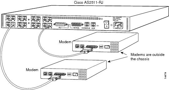
External Modems on Low-End Access Servers
Some of the Cisco lower-end access servers, such as the Cisco AS2511-RJ shown in Figure 1, have cable connections to external modems. The asynchronous interfaces and lines are inside the access server.
Figure 1 Cisco AS2511-RJ Access Server
When you configure modems to function with your access server, you must provide initialization strings and other settings on the modem to tell it how to function with the access server.
This section assumes that you have already physically attached the modem to the access server. If not, refer to the user guide or installation and configuration guide for your access server for information about attaching modems.
Automatically Configuring an External Modem
The Cisco IOS software can issue initialization strings automatically, in a file called a modemcap, for most types of modems externally attached to the access server. A modemcap is a series of parameter settings that are sent to your modem to configure it to interact with the Cisco device in a specified way. The Cisco IOS software defines modemcaps that have been found to properly initialize most modems so that they function properly with Cisco routers and access servers. For Cisco IOS Release 12.2, these modemcaps have the following names:
•
•
•
•
•
•
•
•
•
•
•
1The hayes_optima modemcap is not recommended for use; instead, use the default modemcap.Enter these modemcap names with the modemcap entry command.
If your modem is not on this list and if you know what modem initialization string you need to use with it, you can create your own modemcap; see the following procedure "Using the Modem Autoconfigure Type Modemcap Feature." To have the Cisco IOS software determine what type of modem you have, use the modem autoconfigure discovery command to configure it, as described in the procedure "Using the Modem Autoconfigure Discovery Feature."
Using the Modem Autoconfigure Type Modemcap Feature
Step 1
The following example defines modemcap MODEMCAPNAME:
Router(config)# modemcap edit MODEMCAPNAME miscellaneous &FS0=1&D3Step 2
Router# terminal monitorRouter# debug confmodemModem Configuration Database debugging is onRouter# configure terminalEnter configuration commands, one per line. End with CNTL/Z.Router(config)# line 33 34Router(config-line)# modem autoconfigure type MODEMCAPNAMERouter(config-line)#Jan 16 18:12:59.643: TTY34: detection speed (115200) response ---OK---Jan 16 18:12:59.643: TTY34: Modem command: --AT&FS0=1&D3--Jan 16 18:12:59.659: TTY33: detection speed (115200) response ---OK---Jan 16 18:12:59.659: TTY33: Modem command: --AT&FS0=1&D3--Jan 16 18:13:00.227: TTY34: Modem configuration succeededJan 16 18:13:00.227: TTY34: Detected modem speed 115200Jan 16 18:13:00.227: TTY34: Done with modem configurationJan 16 18:13:00.259: TTY33: Modem configuration succeededJan 16 18:13:00.259: TTY33: Detected modem speed 115200Jan 16 18:13:00.259: TTY33: Done with modem configurationUsing the Modem Autoconfigure Discovery Feature
If you prefer the modem software to use its autoconfigure mechanism to configure the modem, use the modem autoconfigure discovery command.
The following example shows how to configure modem autoconfigure discovery mode:
Router# terminal monitorRouter# debug confmodemModem Configuration Database debugging is onRouter# configure terminalEnter configuration commands, one per line. End with CNTL/Z.Router(config)# line 33 34Router(config-line)# modem autoconfigure discoveryJan 16 18:16:17.724: TTY33: detection speed (115200) response ---OK---Jan 16 18:16:17.724: TTY33: Modem type is defaultJan 16 18:16:17.724: TTY33: Modem command: --AT&F&C1&D2S0=1H0--Jan 16 18:16:17.728: TTY34: detection speed (115200) response ---OK---Jan 16 18:16:17.728: TTY34: Modem type is defaultJan 16 18:16:17.728: TTY34: Modem command: --AT&F&C1&D2S0=1H0--Jan 16 18:16:18.324: TTY33: Modem configuration succeededJan 16 18:16:18.324: TTY33: Detected modem speed 115200Jan 16 18:16:18.324: TTY33: Done with modem configurationJan 16 18:16:18.324: TTY34: Modem configuration succeededJan 16 18:16:18.324: TTY34: Detected modem speed 115200Jan 16 18:16:18.324: TTY34: Done with modem configuration
Manually Configuring an External Modem
If you cannot configure your modem automatically, you must configure it manually. This section describes how to determine and issue the correct initialization string for your modem and how to configure your modem with it.
Modem command sets vary widely. Although most modems use the Hayes command set (prefixing commands with at), Hayes-compatible modems do not use identical at command sets.
Refer to the documentation that came with your modem to learn how to examine the current and stored configuration of the modem that you are using. Generally, you enter at commands such as &v, i4, or *o to view, inspect, or observe the settings.
Timesaver
A sample modem initialization string for a US Robotics Courier modem is as follows:
&b1&h1&r2&c1&d3&m4&k1s0=1Modem initialization strings enable the following functions:
•
•
•
•
•
Note
The port speed must not change when a session is negotiated with a remote modem. If the speed of the port on the access server is changed, you must establish a direct Telnet session to the modem and send an at command so that the modem can learn the new speed.
Modems differ in the method that they use to lock the EIA/TIA-232 (serial) port speed. In the modem documentation, vendors use terms such as port-rate adjust, speed conversion, or buffered mode. Enabling error correction often puts the modem in the buffered mode. Refer to your modem documentation to learn how your modem locks speed (check the settings &b, \j, &q, \n, or s-register settings).
RTS and CTS signals must be used between the modem and the access server to control the flow of data. Incorrectly configuring flow control for software or setting no flow control can result in hung sessions and loss of data. Modems differ in the method that they use to enable hardware flow control. Refer to your modem documentation to learn how to enable hardware flow control (check the settings &e, &k, &h, &r, or s-register).
The modem must use the DCD wire to indicate to the access server when a session has been negotiated and is established with a remote modem. Most modems use the setting &c1. Refer to your modem documentation for the DCD settings used with your modem.
The modem must interpret a toggle of the DTR signal as a command to drop any active call and return to the stored settings. Most modems use the settings &d2 or &d3. Refer to your modem documentation for the DTR settings used with your modem.
If a modem is used to service incoming calls, it must be configured to answer a call after a specific number of rings. Most modems use the setting s0=1 to answer the call after one ring. Refer to your modem documentation for the settings used with your modem.
Supporting Dial-In Modems
The Cisco IOS software supports dial-in modems that use DTR to control the off-hook status of the telephone line. This feature is supported primarily on old-style modems, especially those in Europe. To configure the line to support this feature, use the following command in line configuration mode:
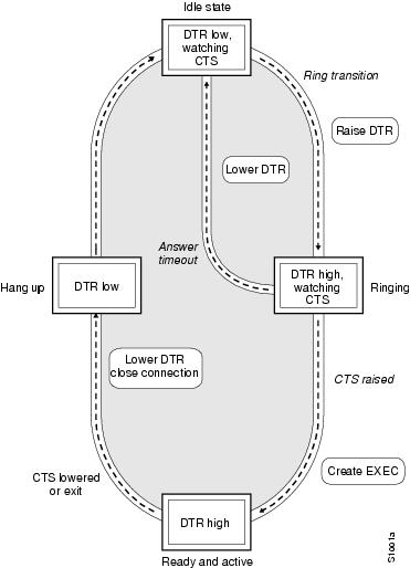
Figure 2 illustrates the modem callin command. When a modem dialing line is idle, it has its DTR signal at a low state and waits for a transition to occur on the data set ready (DSR) input. This transition causes the line to raise the DTR signal and start watching the CTS signal from the modem. After the modem raises CTS, the Cisco IOS software creates an EXEC session on the line. If the timeout interval (set with the modem answer-timeout command) passes before the modem raises the CTS signal, the line lowers the DTR signal and returns to the idle state.
Figure 2 EXEC Creation on a Line Configured for Modem Dial-In
Note
Although you can use the modem callin line configuration command with newer modems, the modem dialin line configuration command described in this section is more appropriate. The modem dialin command frees up CTS input for hardware flow control. Modern modems do not require the assertion of DTR to answer a phone line (that is, to take the line off-hook).
Testing the Modem Connection
To test the connection, send the modem the AT command to request its attention. The modem should respond with "OK." For example:
atOKIf the modem does not reply to the at command, perform the following steps:
Step 1
Step 2
Modem state: IdleModem hardware state: CTS noDSR DTR RTSIf the output displays "no CTS" for the modem hardware state, the modem is not connected, is not powered up, is waiting for data, or might not be configured for hardware flow control.
Step 3
Table 1 Matching Line Speed with Transmission Rate
(in bits per second)9600
38400
14400
57600
28800
115200
To verify the line speed, use the show run EXEC command. The line configuration fragment appears at the tail end of the output.
The following example shows that lines 7 through 9 are transmitting at 115200 bits per second (bps). Sixteen 28800-kbps modems are connected to a Cisco AS2511-RJ access server via a modem cable.
Router# show runBuilding configuration...Current configuration:. . .!line 1 16login localmodem InOutspeed 115200transport input allflowcontrol hardwarescript callback callbackautoselect pppautoselect during-loginStep 4
Step 5
Managing Telnet Sessions
You communicate with an external modem by establishing a direct Telnet session from the asynchronous line on the access server, which is connected to the modem. This process is also referred to as reverse Telnet. Performing a reverse Telnet means that you are initiating a Telnet session out the asynchronous line, instead of accepting a connection into the line (called a forward connection).
Note
To establish a direct Telnet session to an external modem, determine the IP address of your LAN (Ethernet) interface, and then enter a Telnet command to port 2000 + n on the access server, where n is the line number to which the modem is connected. For example, to connect to the modem attached to line 1, enter the following command from an EXEC session on the access server:
Router# telnet 172.16.1.10 2001Trying 172.16.1.10, 2001 ... OpenThis example enables you to communicate with the modem on line 1 using the AT (attention) command set defined by the modem vendor.
Timesaver
Suspending Telnet Sessions:
When you are connected to an external modem, the direct Telnet session must be terminated before the line can accept incoming calls. If you do not terminate the session, it will be indicated in the output of the show users command and will return a modem state of ready if the line is still in use. If the line is no longer in use, the output of the show line value command will return a state of idle. Terminating the Telnet session requires first suspending it, then disconnecting it.
To suspend a Telnet session, perform the following steps:
Step 1
- suspend keystroke -Router#
Note
Step 2
Router# whereConn Host Address Byte Idle Conn Name* 1 172.16.1.10 172.16.1.10 0 0 172.16.1.102 172.16.1.11 172.16.1.11 0 12 modem2Step 3
Router# telnet modem2Trying modem2 (172.16.1.11, 2002) ... Open- suspend keystroke -Router#Step 4
Router# disconnect line 1Closing connection to 172.16.1.10 [confirm] yRouter# disconnect line 2Closing connection to 172.16.1.11 [confirm] yRouter#
Modem Troubleshooting Tips
Table 2Table 2 contains troubleshooting tips on modem access and control.
Checking Other Modem Settings
This section defines other settings that might be needed or desirable, depending on your modem.
Error correction can be negotiated between two modems to ensure a reliable data link. Error correction standards include Link Access Procedure for Modems (LAPM) and MNP4. V.42 error correction allows either LAPM or MNP4 error correction to be negotiated. Modems differ in the way they enable error correction. Refer to your modem documentation for the error correction methods used with your modem.
Data compression can be negotiated between two modems to allow for greater data throughput. Data compression standards include V.42bis and MNP5. Modems differ in the way they enable data compression. Refer to your modem documentation for the data compression settings used with your modem.
Cisco and the Cisco Logo are trademarks of Cisco Systems, Inc. and/or its affiliates in the U.S. and other countries. A listing of Cisco's trademarks can be found at www.cisco.com/go/trademarks. Third party trademarks mentioned are the property of their respective owners. The use of the word partner does not imply a partnership relationship between Cisco and any other company. (1005R)
Any Internet Protocol (IP) addresses used in this document are not intended to be actual addresses. Any examples, command display output, and figures included in the document are shown for illustrative purposes only. Any use of actual IP addresses in illustrative content is unintentional and coincidental.
© 2001-2008 Cisco Systems, Inc. All rights reserved.