-
Cisco IOS Voice Command Reference
-
About Cisco IOS Software Documentation
-
Using Cisco IOS Software
-
Commands: A
-
Commands: B
-
Commands:cac master through call application stats
-
Commands: call application voice through call-denial
-
Commands: call fallback through called-number (dial-peer)
-
Commands: caller-id (dial peer) through ccm-manager switchover-to-backup
-
Commands: ccs connect (controller) through clear vsp statistics
-
Commands: clid through cptone
-
Commands: default (MGCP profile) through direct-inward-dial
-
Commands: disable-early-media 180 through dualtone
-
Commands: E
-
Commands: F
-
Commands: G
-
Commands: H
-
Commands: icpif through irq global-request
-
Commands: isdn bind-l3 through ixi transport http
-
Commands: K
-
Commands: L
-
Commands: map q850-cause through mgcp package-capability
-
Commands: mgcp persistent through mmoip aaa send-id secondary
-
Commands: mode (ATM/T1/E1 controller) through mwi-server
-
Commands: N
-
Commands: O
-
Commands: package through pattern
-
Commands: permit hostname through proxy h323
-
Commands: Q
-
Commands: R
-
Commands: sccp through service-type call-check
-
Commands: session through sgcp tse payload
-
Commands: show aal2 profile through show call filter match-list
-
Commands: show call history fax through show debug condition
-
Commands: show dial-peer video through show gatekeeper zone status
-
Commands: show gateway through show modem relay statistics
-
Commands: show mrcp client session active through show sgcp statistics
-
Commands: show sip service through show trunk hdlc
-
Commands: show vdev through show voice statistics memory-usage
-
Commands: show voice translation-profile through shutdown (voice-port)
-
Commands: signal through srv version
-
Commands: ss7 mtp2-variant through switchover method
-
Commands: target carrier-id through threshold noise
-
Commands: timeout (auto-config application) through timing clear-wait
-
Commands:timing delay-duration through type (voice)
-
Commands: U
-
Commands: vad (dial peer) through voice class dualtone-detect-params
-
Commands: voice class h323 through vxml tree memory
-
Commands: W
-
Commands: Z
-
 Feedback
Table Of Contents
Cisco IOS Voice Commands:
L
This chapter contains commands to configure and maintain Cisco IOS voice applications. The commands are presented in alphabetical order. Some commands required for configuring voice may be found in other Cisco IOS command references. Use the command reference master index or search online to find these commands.
For detailed information on how to configure these applications and features, refer to the Cisco IOS Voice Configuration Guide.
link (RLM)
To enable a Redundant Link Manager (RLM) link, use the link command in RLM configuration mode. To disable this function, use the no form of this command.
link {hostname name | address ip-address} source loopback-source weight factor
no link {hostname name | address ip-address} source loopback-source weight factor
Syntax Description
Command Default
Disabled
Command Modes
RLM configuration
Command History
Usage Guidelines
This command is a preference-weighted multiple entries command. Within the same server, the link preference is specified in weighting.
Examples
The following example specifies the RLM group (network access server), device name, and link addresses and their weighting preferences:
rlm group 1server r1-serverlink address 10.1.4.1 source Loopback1 weight 4link address 10.1.4.2 source Loopback2 weight 3lmr duplex half
To have the voice path for a voice port operate in half duplex mode, use the lmr duplex half command in voice-port configuration mode. To return to the default, use the no form of this command.
lmr duplex half
no lmr duplex half
Syntax Description
This command has no arguments or keywords.
Command Default
Full duplex mode
Command Modes
Voice-port configuration
Command History
12.3(4)XD
This command was introduced.
12.3(7)T
This command was integrated into Cisco IOS Release 12.3(7)T.
Usage Guidelines
When a radio system is receiving voice traffic from the radio, operating the voice path in half duplex mode prevents the speaker from being interrupted and prevents the voice stream from being fed back to itself.
Examples
In the following example, the voice path for voice port 1/0/0 on a Cisco 3700 series router is set to operate in half duplex mode:
voice-port 1/0/0lmr duplex halflmr e-lead
To define the use of the E-lead in signaling between the ear and mouth (E&M) voice port on the router and the attached Land Mobile Radio (LMR) device, use the lmr e-lead command in voice-port configuration mode. To return to the default use of the E-lead, use the no form of this command.
lmr e-lead {inactive | seize | voice}
no lmr e-lead {inactive | seize | voice}
Syntax Description
Command Default
seize
Command Modes
Voice-port configuration
Command History
12.3(4)XD
This command was introduced.
12.3(7)T
This command was integrated into Cisco IOS Release 12.3(7)T.
Usage Guidelines
The lmr e-lead command has an effect on an ear and mouth (E&M) voice port only if the signal type for that port is LMR. The lmr e-lead command is effective only if the attached LMR device operates under E-lead control. Use the lmr e-lead command to configure the voice port when using private line, automatic ringdown (PLAR) connections. The E-lead connects to the Push To Talk (PTT) of the LMR system.
Examples
In the following example, packet transmission from the E&M voice port on a Cisco 3745 to an attached LMR radio system is disabled:
lmr e-lead inactiveRelated Commands
lmr m-lead
Defines the use of the M-lead in signaling between the E&M voice port on the router and the attached LMR device.
lmr ip-vad
To configure the Land Mobile Radio (LMR) digital signal processor (DSP) on a Cisco 2800 series integrated services router to report a voice packet arrival event only if the packet contains voice energy, use the lmr ip-vad command in voice-port configuration mode. To disable this feature, use the no form of this command.
lmr ip-vad
no lmr ip-vad
Syntax Description
This command has no arguments or keywords.
Command Default
Any voice packet received from the IP network side triggers the DSP to report a voice packet arrival event to the Cisco IOS software.
Command Modes
Voice-port configuration
Command History
Usage Guidelines
The lmr ip-vad command applies to a voice interface card (VIC) in a Cisco 2800 series integrated services router if the VIC is one of the following types of ear and mouth (E&M) interfaces:
•
VIC2-2E/M with signal type LMR
•
The lmr ip-vad command configures the LMR DSP to report voice activity detection (VAD) status change events (rather than voice packet arrival events) for a supported voice interface in a Cisco 2800 series integrated services router.
Examples
The following example shows a sequence of commands that can be used to configure a voice port so that a voice packet arrival event is reported to the Cisco IOS software on the router only if the packet contains voice energy.
Router(config)# voice-port 1/1/0Router(config-voiceport)# signal lmrRouter(config-voiceport)# lmr ip-vadRelated Commands
signal
Configures the type of signaling to be used for a voice port.
voice-port
Enters voice-port configuration mode.
lmr led-on
To use the ear and mouth (E&M) LED to indicate the E-lead and M-lead status, use the lmr led-on command in voice-port configuration mode. To return to the default use of the E&M LED, use the no form of this command.
lmr led-on
no lmr led-on
Syntax Description
This command has no arguments or keywords.
Command Default
The E&M LED indicates voice port activity only.
Command Modes
Voice-port configuration
Command History
12.3(4)XD
This command was introduced.
12.3(7)T
This command was integrated into Cisco IOS Release 12.3(7)T.
Usage Guidelines
The lmr e-lead command is available on an E&M voice port only if the signal type for that port is Land Mobile Radio (LMR). This command enables the use of the E&M LED to indicate the E-lead and M-lead status as follows:
•
•
•
The default behavior of the E&M LED is to light up when there is activity on the voice port and to turn off when there is no activity.
Examples
The following example specifies that the E&M LED is used to indicate the E-lead and M-lead status:
voice-port 1/0/0lmr led-onlmr m-lead
To define the use of the M-lead in signaling between the ear and mouth (E&M) voice port on the router and the attached Land Mobile Radio (LMR) device, use the lmr m-lead command in voice-port configuration mode. To return to the default use of the M-lead, use the no form of this command.
lmr m-lead {inactive | audio-gate-in | dialin}
no lmr m-lead {inactive | audio-gate-in | dialin}
Syntax Description
Command Default
inactive
Command Modes
Voice-port configuration
Command History
12.3(4)XD
This command was introduced.
12.3(7)T
This command was integrated into Cisco IOS Release 12.3(7)T.
Usage Guidelines
The lmr m-lead command has an effect on an ear and mouth (E&M) voice port only if the signal type for that port is LMR. The lmr e-lead command is effective only if the attached LMR device operates under M-lead control. The M-lead corresponds to the Carrier Operated Relay (COR) of the LMR system, which indicates receive activity on the LMR system.
Examples
In the following example, an LMR radio system attached to the E&M voice port on a Cisco 3745 is allowed to transmit audio by first raising the E-lead, then transmitting:
lmr m-lead dialinRelated Commands
lmr e-lead
Defines the use of the E-lead in signaling between the E&M voice port on the router and the attached LMR device.
load-balance
To configure load balancing, use the load-balance command in gatekeeper configuration mode. To disable load balancing, use the no form of this command.
load-balance [endpoints max-endpoints] [calls max-calls] [cpu max-%cpu]
[memory max-%mem-used]no load-balance [endpoints max-endpoints] [calls max-calls] [cpu max-%cpu]
[memory max-%mem-used]Syntax Description
Command Default
Load balancing is performed by the gatekeeper.
Command Modes
Gatekeeper configuration
Command History
12.1(2)XM
This command was introduced.
12.2(2)T
This command was integrated into Cisco IOS Release 12.2(2)T.
12.2(2)XB1
This command was implemented on the Cisco AS5850.
Usage Guidelines
Load balancing occurs when one gatekeeper reaches the default or the configured load level. Upon reaching the load-level threshold, the gatekeeper begins sending alternate gatekeeper information in Registration, Admission, and Status (RAS) messages, and the gateways then attempt to migrate from the loaded gatekeeper to its least busy alternate. The move is permanent; endpoints are not actively moved back to the original gatekeeper if it stabilizes. However, they may return to that gatekeeper if the new gatekeeper reaches a load threshold and transfers them again. The gatekeepers share the load, but they may not have equal shares. The process of load balancing allows for more effective zone management.
Examples
The following example configures load balancing:
load-balance endpoints 200 calls 100 cpu 75 memory 80Related Commands
local
To define the local domain, including the IP address and port that the border element (BE) should use for interacting with remote BEs, use the local command in Annex G configuration mode. To reset to the default, use the no form of this command.
local ip ip-address [port local-port]
no local ip
Syntax Description
ip ip-address
IP address of the local border element.
port local-port
(Optional) Port number of the local border element, which is used for exchanging Annex G messages. Default is 2099.
Command Default
Port number: 2099
Command Modes
Annex G configuration
Command History
Usage Guidelines
The local IP address can be a virtual Hot Standby Routing Protocol (HSRP) address for high reliability and availability. You can configure multiple gatekeepers and BEs identically and use HSRP to designate a primary BE and other standby BEs. If the primary BE is down, a standby BE operates in its place.
Examples
The following example sets the IP address and port that the BE should use. (Note that this example uses a nonstandard port number. If you do not want to use a nonstandard port number, use the default value of 2099.)
Router(config)# call-router h323-annexg be20Router(config-annexg)# local ip 121.90.10.80 port 2010Related Commands
call-router
Enables the Annex G border element configuration commands.
show call-router status
Displays the Annex G BE status.
localhost dns (global)
To define a local hostname used for locally generated gateway URLs, use the localhost dns command in global configuration mode. To disable the local hostname, use the no form of this command.
localhost dns:host-name-string
no localhost dns:host-name-string
Syntax Description
Command Default
No local hostnames used for locally generated gateway URLs are sent.
Command Modes
Global configuration
Command History
Usage Guidelines
Configuring the localhost dns command under the VoIP dial peer overrides the global voice-class sip localhost command.
Examples
The following example defines a local hostname used for a locally generated gateway URL:
Router(config)# localhost dns:customer1.comRelated Commands
loopback (controller)
To set the loopback method for testing a T1 or E1 interface, use the loopback command in controller configuration mode. To reset to the default, use the no form of this command.
loopback {diagnostic | local {payload | line} | remote {v54 channel-group channel-number | iboc | esf {payload | line}}}
no loopback
Syntax Description
Command Default
No loopback is configured.
Command Modes
Controller configuration
Command History
Usage Guidelines
You can use a loopback test on lines to detect and distinguish equipment malfunctions caused either by the line and channel service unit/digital service unit (CSU/DSU) or by the interface. If correct data transmission is not possible when an interface is in loopback mode, the interface is the source of the problem.
Examples
The following example sets the diagnostic loopback method on controller T1 0/0:
controller t1 0/0loopback diagnosticThe following example sets the payload loopback method on controller E1 0/0:
controller e1 0/0loopback local payloadloop-detect
To enable loop detection for T1, use the loop-detect command in controller configuration mode. To cancel loop detection, use the no form of this command.
loop-detect
no loop-detect
Syntax Description
This command has no arguments or keywords.
Command Default
Loop detection is disabled.
Command Modes
Controller configuration
Command History
Usage Guidelines
This command applies to Voice over Frame Relay and Voice over ATM.
Examples
The following example configures loop detection for controller T1 0:
controller t1 0loop-detectRelated Commands
loopback (interface)
Diagnoses equipment malfunctions between an interface and a device.
loss-plan
To specify the analog-to-digital gain offset for an analog Foreign Exchange Office (FXO) or Foreign Exchange Station (FXS) voice port, use the loss-plan command in voice-port configuration mode. To reset to the default, use the no form of this command.
loss-plan {plan1 | plan2 | plan3 | plan4 | plan5 | plan6 | plan7 | plan8 | plan9}
no loss-plan
Syntax Description
Command Default
FXO: A-D gain = 0 dB, D-A gain = 0 dB (loss plan 1)
FXS: A-D gain = -3 dB, D-A gain = -3 dB (loss plan 1)Command Modes
Voice-port configuration
Command History
Usage Guidelines
This command sets the analog signal level difference (offset) between the analog voice port and the digital signal processor (DSP). Each loss plan specifies a level offset in both directions—from the analog voice port to the DSP (A-D) and from the DSP to the analog voice port (D-A).
Use this command to obtain the required levels of analog voice signals to and from the DSP.
Examples
The following example configures FXO voice port 1/6 for a -3 dB offset from the voice port to the DSP and for a 0 dB offset from the DSP to the voice port:
voice-port 1/6loss-plan plan3The following example configures FXS voice port 1/1 for a 0 dB offset from the voice port to the DSP and for a -7 dB offset from the DSP to the voice port:
voice-port 1/1loss-plan plan6Related Commands
lrq forward-queries
To enable a gatekeeper to forward location request (LRQ) messages that contain E.164 addresses that match zone prefixes controlled by remote gatekeepers, use the lrq forward-queries command in gatekeeper configuration mode. To disable this function, use the no form of this command.
lrq forward-queries
no lrq forward-queries
Syntax Description
This command has no arguments or keywords.
Command Default
Disabled
Command Modes
Gatekeeper configuration
Command History
12.0(3)T
This command was introduced on the following platforms: Cisco 2500 series, Cisco 3600 series, and Cisco MC3810.
Usage Guidelines
LRQ forwarding is dependent on a Cisco nonstandard field that first appeared in Cisco IOS Release 12.0(3)T. This means that any LRQ message received from a non-Cisco gatekeeper or any gatekeeper running a Cisco IOS software image prior to Cisco IOS Release 12.0(3)T is not forwarded.
The routing of E.164-addressed calls is dependent on the configuration of zone prefix tables (for example, area code definitions) on each gatekeeper. Each gatekeeper is configured with a list of prefixes controlled by itself and by other remote gatekeepers. Calls are routed to the zone that manages the matching prefix. Thus, in the absence of a directory service for such prefix tables, you, the network administrator, may have to define extensive lists of prefixes on all the gatekeepers in your administrative domain.
To simplify this task, you can select one of your gatekeepers as the "directory" gatekeeper and configure that gatekeeper with the complete list of prefixes and the lrq forward-queries command. You can then simply configure all the other gatekeepers with their own prefixes and the wildcard prefix "*" for your directory gatekeeper.
This command affects only the forwarding of LRQ messages for E.164 addresses. LRQ messages for H.323-ID addresses are never forwarded.
Examples
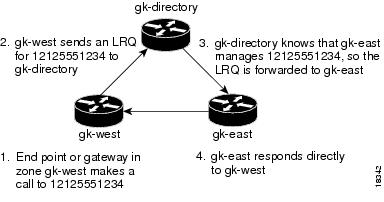
The following example selects one gatekeeper as the directory gatekeeper. See Figure 4Figure 4.
Figure 4 Example Scenario with Directory Gatekeeper and Two Remote Gatekeepers
Configuration on gk-directory
On the directory gatekeeper called gk-directory, identify all the prefixes for all the gatekeepers in your administrative domain:
zone local gk-directory cisco.com
zone remote gk-west cisco.com 172.16.1.1
zone remote gk-east cisco.com 172.16.2.1zone prefix gk-west 1408.......zone prefix gk-west 1415.......zone prefix gk-west 1213.......zone prefix gk-west 1650.......zone prefix gk-east 1212.......zone prefix gk-east 1617.......lrq forward-queriesConfiguration on gk-west
On the gatekeeper called gk-west, configure all the locally managed prefixes for that gatekeeper:
zone local gk-west cisco.comzone remote gk-directory cisco.com 172.16.2.3zone prefix gk-west 1408.......zone prefix gk-west 1415.......zone prefix gk-west 1213.......zone prefix gk-west 1650.......zone prefix gk-directory *Configuration on gk-east
On the gatekeeper called gk-east, configure all the locally managed prefixes for that gatekeeper:
zone local gk-east cisco.comzone remote gk-directory cisco.com 172.16.2.3zone prefix gk-east 1212.......zone prefix gk-east 1617.......zone prefix gk-directory *When an endpoint or gateway in zone gk-west makes a call to 12125551234, gk-west sends an LRQ message for that E.164 address to gk-directory, which forwards the message to gk-east. Gatekeeper gk-east responds directly to gk-west.
Related Commands
lrq reject-unknown-prefix
Enables the gatekeeper to reject all LRQ messages for zone prefixes that are not configured.
lrq lrj immediate-advance
To enable the Cisco IOS gatekeeper to immediately send a sequential location request (LRQ) message to the next zone after it receives a location reject (LRJ) message from a gatekeeper in the current zone, use the lrq lrj immediate-advance command in gatekeeper configuration mode. To disable this function, use the no form of this command.
lrq lrj immediate-advance
no lrq lrj immediate-advance
Syntax Description
This command has no arguments or keywords.
Command Default
Disabled
Command Modes
Gatekeeper configuration
Command History
12.2(4)T
This command was introduced. This command does not support the Cisco AS5300, Cisco AS5350, and Cisco AS5400 series in this release.
Usage Guidelines
In a network in which LRQ messages are forwarded through multiple gatekeepers along a single path, a single LRQ message sent from a gatekeeper could solicit multiple LRJ and location confirmation (LCF) responses. If an LRJ response is received first, a potentially unnecessary LRQ message could be sent to the next zone, increasing traffic.
To avoid this problem, perform the following:
•
•
Examples
The following example enables the gatekeeper to immediately send a sequential LRQ message to the next zone after it receives an LRJ message from a gatekeeper in the current zone.
lrq lrj immediate-advanceRelated Commands
lrq reject-resource-low
To configure a gatekeeper to notify a sending gatekeeper on receipt of a location request (LRQ) message that no terminating endpoints are available, use the lrq reject-resource-low command in gatekeeper configuration mode. To disable this function, use the no form of this command.
lrq reject-resource-low
no lrq reject-resource-low
Syntax Description
This command has no arguments or keywords.
Command Default
Disabled
Command Modes
Gatekeeper configuration
Command History
Examples
The following example causes the gatekeeper to notify the sending gatekeeper on receipt of an LRQ message that no terminating endpoints are available:
Router(config)# gatekeeperRouter(config-gk)# lrq reject-resource-lowlrq reject-unknown-circuit
To enable the gatekeeper to reject a location request (LRQ) message that contains an unknown destination circuit, use the lrq reject-unknown-circuit command in gatekeeper configuration mode. To disable the rejection, use the no form of this command.
lrq reject-unknown-circuit
no lrq reject-unknown-circuit
Syntax Description
This command has no keywords or arguments.
Command Default
Disabled
Command Modes
Gatekeeper configuration
Command History
Usage Guidelines
The gatekeeper checks the destination circuit field in each LRQ message. If the field contains a circuit unknown to the gatekeeper and this command is entered, the gatekeeper rejects the LRQ request. If this command is disabled, the gatekeeper tries to resolve the alias without considering the circuit.
Examples
The following example causes the gatekeeper to reject unknown carriers in an LRQ request:
Router(config)# gatekeeperRouter(config-gk)# lrq reject-unknown-circuitRelated Commands
endpoint circuit-id h323id
Assigns a circuit to a non-Cisco endpoint.
show gatekeeper endpoint circuits
Displays the information of all registered endpoints for a gatekeeper.
lrq reject-unknown-prefix
To enable the gatekeeper to reject all location request (LRQ) messages for zone prefixes that are not configured, use the lrq reject-unknown-prefix command in gatekeeper configuration mode. To reenable the gatekeeper to accept and process all incoming LRQ messages, use the no form of this command.
lrq reject-unknown-prefix
no lrq reject-unknown-prefix
Syntax Description
This command has no arguments or keywords.
Command Default
The gatekeeper accepts and processes all incoming LRQ messages.
Command Modes
Gatekeeper configuration
Command History
11.3(6)NA2
This command was introduced on the Cisco 2500 series and Cisco 3600 series.
12.0(3)T
This command was integrated into Cisco IOS Release 12.0(3)T.
Usage Guidelines
Use this command to configure the gatekeeper to reject any incoming LRQ messages for a destination E.164 address that does not match any of the configured zone prefixes.
Whether or not you use this command, the following is true when the E.164 address matches a zone prefix:
•
•
If you do not use this command and the target address does not match any known local or remote prefix, the default behavior is to attempt to service the call using one of the local zones. If this default behavior is not suitable for your site, use this command on your router to force the gatekeeper to reject such requests.
Examples
Consider the following gatekeeper configuration:
zone local gk408 cisco.comzone local gk415 cisco.comzone prefix gk408 1408.......zone prefix gk415 1415.......lrq reject-unknown-prefixIn this sample configuration, the gatekeeper is configured to manage two zones. One zone contains gateways with interfaces in the 408 area code, and the second zone contains gateways in the 415 area code. Then using the zone prefix command, the gatekeeper is configured with the appropriate prefixes so that calls to those area codes hop off in the optimal zone.
Now say some other zone has been erroneously configured to route calls to the 212 area code to this gatekeeper. When the LRQ message for a number in the 212 area code arrives at this gatekeeper, the gatekeeper fails to match the area code, and the message is rejected.
If this was your only site that had any gateways in it and you wanted your other sites to route all calls that require gateways to this gatekeeper, you can undo the lrq reject-unknown-prefix command by simply using the no lrq reject-unknown-prefix command.Now when the gatekeeper receives an LRQ message for the address 12125551234, it attempts to find an appropriate gateway in either one of the zones gk408 or gk415 to service the call.
Related Commands
lrq forward-queries
Enables a gatekeeper to forward LRQ messages that contain E.164 addresses that match zone prefixes controlled by remote gatekeepers.
lrq timeout blast window
To configure the timeout window for use when sending multiple location request (LRQ) messages (either sequentially or simultaneously), use the lrq timeout blast window command in gatekeeper configuration mode. To reset to the default, use the no form of this command.
lrq timeout blast window seconds
no lrq timeout blast window
Syntax Description
Command Default
6 seconds
Command Modes
Gatekeeper configuration
Command History
12.1(2)T
This command was introduced on the following platforms: Cisco 2500 series, Cisco 2600 series, Cisco 3600 series, Cisco 7200 series, and Cisco MC3810.
Examples
The following example sets the window to 3 seconds:
lrq timeout blast window 3Related Commands
gatekeeper gw-type-prefix
Sets the gatekeepers responsible for each technology prefix.
zone prefix
Adds a prefix to a gatekeeper's zone list.
lrq timeout seq delay
To configure the delay for use when sending location request (LRQ) messages sequentially, use the lrq timeout seq delay command in gatekeeper configuration mode. To reset to the default, use the no form of this command.
lrq timeout seq delay value
no lrq timeout seq delay
Syntax Description
value
Duration of the delay, in 100-millisecond units.Range is from 1 to 10. The default is 5 (500 ms or 0.5 seconds).
Command Default
Five 100-millisecond units (500 ms or 0.5 seconds)
Command Modes
Gatekeeper configuration
Command History
12.1(2)T
This command was introduced on the following platforms: Cisco 2500 series, Cisco 2600 series, Cisco 3600 series, Cisco 7200 series, and Cisco MC3810.
Examples
The following example sets the window to 300 milliseconds:
lrq timeout seq delay 3Related Commands
gatekeeper gw-type-prefix
Sets the gatekeepers responsible for each technology prefix.
zone prefix
Adds a prefix to a gatekeeper's zone list.