- このマニュアルについて
- ML シリーズ カード の概要
- CTC の動作
- 初期設定
- インターフェイスの設定
- POS の設定
- ブリッジの設定
- STP および RSTP の設定
- VLAN の設定
- IEEE 802.1Q および レイヤ 2 プロトコ ル のトンネリング設定
- リンク集約の設定
- ネットワーク プロトコルの設定
- IRB の設定
- VRF Lite の設定
- QoS の設定
- SDM の設定
- ACL の設定
- RPR の設定
- EoMPLS の設定
- ML シリーズ カードのセキュリティ設定
- ONS イーサネット カード上の POS
- RMON の設定
- SNMP の設定
- E シリーズおよび G シリーズ イーサネットの運用
- CE-100T-8 イーサネットの運用
- CE-1000-4 イーサネットの動作
- コマンド リファレンス
- サポートされていない CLI コマンド
- テクニカル サポートの利用方法
- 索引
Cisco ONS 15454/15454 SDH/15327 イーサネット カード ソフトウェア フィーチャ コンフィギュレーション ガイド Cisco IOS Release 12.2(28)SV CTC and Documentation Release 7.0
偏向のない言語
この製品のマニュアルセットは、偏向のない言語を使用するように配慮されています。このマニュアルセットでの偏向のない言語とは、年齢、障害、性別、人種的アイデンティティ、民族的アイデンティティ、性的指向、社会経済的地位、およびインターセクショナリティに基づく差別を意味しない言語として定義されています。製品ソフトウェアのユーザーインターフェイスにハードコードされている言語、RFP のドキュメントに基づいて使用されている言語、または参照されているサードパーティ製品で使用されている言語によりドキュメントに例外が存在する場合があります。シスコのインクルーシブランゲージに対する取り組みの詳細は、こちらをご覧ください。
翻訳について
このドキュメントは、米国シスコ発行ドキュメントの参考和訳です。リンク情報につきましては、日本語版掲載時点で、英語版にアップデートがあり、リンク先のページが移動/変更されている場合がありますことをご了承ください。あくまでも参考和訳となりますので、正式な内容については米国サイトのドキュメントを参照ください。
- Updated:
- 2017年6月5日
章のタイトル: RPR の設定
RPR の設定
この章では、ML シリーズ カードの Resilient Packet Ring(RPR; 復元パケット リング)、RPR Link Fault Propagation(LFP; リンク障害伝播)、および Dual RPR Interconnect(DRPRI; 二重 RPR 相互接続)の設定方法について説明します。
RPR の概要
RPR は、レイヤ 2 レベルで動作する新しいMAC(メディア アクセス制御)プロトコルです。RPR は、SONET/SDH リング トポロジー上でのイーサネットの転送に非常に適しており、複数の ML シリーズ カードをイネーブルにして、1 つの機能ネットワーク セグメントまたは Shared Packet Ring(SPR; 共有パケット リング)にすることが可能です。RPR は、このような役割における IEEE 802.1D Spanning Tree Protocol(STP; スパニング ツリー プロトコル)、IEEE 802.1W Rapid Spanning Tree Protocol(RSTP; 高速スパニング ツリー プロトコル)、SONET/SDH などの初期のスキームの限界を克服します。IEEE 802.17 ドラフトは Cisco ML シリーズ RPR 実装の参照用として使用されていましたが、現在の ML シリーズ カード RPR プロトコルは、IEEE 802.17 の条項とはまったく適合しません。
SONET/SDH 回線の役割
SPR 内の ML シリーズ カードは、ポイントツーポイント STS/STM 回線を介して、直接または間接的に接続する必要があります。ポイントツーポイント STS/STM 回線は ONS ノード上で設定され、保護回線または非保護回線のいずれかで ONS ノードの SONET/SDH トポロジー上で転送されます。
SONET/SDH メカニズムによって保護されていない回線上の場合、RPR は SONET/SDH 保護回線が必要とする冗長保護パスを使用せずに、復元機能を提供します。そのため、トラフィック量を増やすことができます。また、RPR はリングの帯域幅全体を使用するため、STP や RSTP のようにセグメントをブロックしません。
パケット処理動作
ML シリーズ カードに RPR が設定されていて、SPR の一部にした場合、ML シリーズ カードはリング トポロジーとみなされます。パケットが、特定の ML シリーズ カードのイーサネット ポート経由でブリッジングされたネットワーク装置宛てでない場合、ML シリーズ カードは、リング アーキテクチャの巡回パスを信頼して、SONET/SDH 回線に沿ってこの中継トラフィックの転送を続け、パケットが最終的に宛先に到達することを保証します。これにより、宛先ではない ML シリーズ カード経由で通過するパケットをキューに入れて処理する必要がなくなります。レイヤ 2 または レイヤ 3 から見ると、RPR 全体が 1 つの共有ネットワーク セグメントのように見えます。
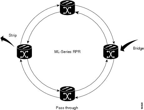
RPR が設定された ML シリーズ カードは、ブリッジ、パススルー、ストリッピングという 3 つの基本的なパケット処理動作を行います。図17-1 に、これらの動作を示します。ブリッジングは、ML シリーズのイーサネット ポートと、リングを巡回する SONET/SDH 回線に使用される Packet-over-SONET/SDH(POS)ポート間を接続し、パケットを渡します。パススルーにより、パケットは ML シリーズ カード経由でリング内を巡回します。また、ストリッピングはリングからパケットを除去し廃棄します。
RPR プロトコルが送信パケットのヘッダー情報を使用することで、インターフェイスはパケットに適用する必要のある動作を迅速に決定できます。また、RPR プロトコルはパケットの送信元および宛先アドレスを使用して、リング方向を選択します。フロー ベースのロード シェアリングにより、同じ送信元および宛先のアドレス ペアが組み込まれたすべてのパケットを同じ方向に送信し、正しい順で宛先に着信できます。リング方向も、スペース再利用をイネーブルにして、全体的なリング集約帯域幅を増やしています。ユニキャスト パケットは宛先がストリッピングされています。宛先ストリッピングにより、RPR の異なる部分間で同時にトラフィック フローを転送する機能が提供されます。隣接するノード間で双方向に同時にトラフィックを送信できます。また、複数のノードをスパンすることもでき、同じリング帯域幅を効率的に再利用できます。マルチキャスト パケットは送信元がストリッピングされています。
リング ラッピング
ファイバ カット、ノードの障害、ノードの復元、新しいノードの挿入、またはその他のトラフィック上の問題が発生すると、RPR はリング ラップを開始します。この保護メカニズムによって、リンク状態の変更後、または SONET/SDH パス レベルのアラーム受信後に、トラフィックはリング内で反対方向に送信され、元の宛先にリダイレクトされます。ML シリーズ カードのリング ラッピングでは、ユニキャストおよびパススルー トラフィックの 50 ミリ秒未満のコンバージェンス時間が許容されます。RPR のコンバージェンス時間は、SONET/SDH とほぼ同じで、STP や RSTP よりもきわめて高速です。
ML シリーズ カードの RPR は、リング内で発生する単一方向送信と双方向送信の両方の障害に対応します。STP や RSTP とは異なり、RPR の復元はスケーラブルです。リング内で ML シリーズ カードの数が増えても、コンバージェンス時間は延びません。
リング ラップは、デフォルトでは spr wrap immediate で設定され、障害状態に陥ってから 50 ミリ秒内に発生します。spr wrap delay が設定されている場合、POS インターフェイスがリンク ダウンするまでラップが遅れます。CLI pos trigger delay <msec> で指定された時間が経過すると、リンクがダウンします。回線が VCAT の場合、Cico IOS CLI コマンド pos vcat defect delayed も設定する必要があります。この遅延により、RPR に SONET/SDH 帯域幅保護が設定されている場合、レイヤ 2 RPR 保護が有効になる前に、このレイヤ 1 保護を有効にできます。SONET エラーなしでインターフェイスがダウンする場合、キャリア遅延も発生します。図17-2 に、リング ラッピングを示します。
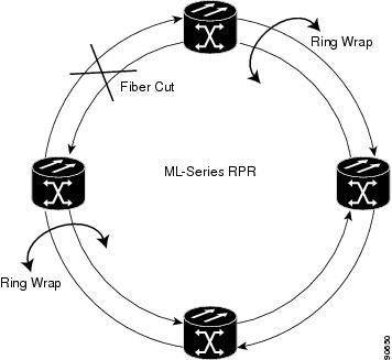
リングに障害が発生した場合、RPR の障害が発生した部分に接続された ML シリーズ カードは SONET/SDH パス アラームを通じて障害を検出します。いずれかの ML シリーズ カードがこのパス AIS 信号を受信すると、カードは信号を受信した POS インターフェイスをラップします。

(注) ML シリーズ カードの RPR コンバージェンス時間は、同じリングで複数の障害が発生したときに、ML シリーズ カードのリロード中に DRPRI が設定された ML シリーズ カード(アクティブ モード)をトラフィックが通過する場合、または ML シリーズ カード間のマイクロコード イメージにミスマッチが発生した場合に、50 ミリ秒を超える可能性があります。
(注) キャリア遅延時間をデフォルトから変更する場合、新しいキャリア遅延時間は、SPR、POS、およびギガビットイーサネットまたはファストイーサネット インターフェイスなど、ML シリーズ カードのすべてのインターフェイスで設定する必要があります。
(注) ML シリーズ カードの POS インターフェイスは通常、POS リンクがダウンまたは RPR がラップしたときに、ONS 15454 STS パス オーバーヘッド(PDI-P)の信号ラベル ミスマッチ障害に関するアラームを遠端に送信します。PDI-P が検出されたとき、Remote Defection Indication - Path(RDI-P; リモート障害表示 - パス)アラームが遠端に送信されているとき、または検出された障害が Generic Framing Procedure(GFP)-Loss of Frame Delineation(LFD)、GFP Client Signal Fail(CSF)、Virtual Concatenation(VCAT)-Loss of Multiframe(LOM)または VCAT-Loss of Sequence(SQM)の場合のみ、ML シリーズ カードの POS インターフェイスは PDI-P を遠端に送信しません。
RPR フレーミング プロセス
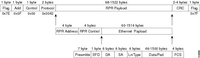
ML シリーズ カードは、固有の RPR フレームと、HDLC または GFP-F フレーミングを使用します。カードは RPR フレーム ヘッダーを各イーサネット フレームに組み込み、RPR フレームを SONET/SDH ペイロードにカプセル化し、SONET/SDH トポロジー上で転送できるようにします。RPR ヘッダーは出力側 ML シリーズ カードで削除されます。図17-3 に、RPR フレームを示します。
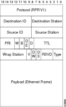
RPR フレーミングとヘッダーには、送信元および宛先ステーション情報の 4 バイト、RPR 制御および Quality of Service(QoS; サービス品質)の 4 バイトなどのフィールド数が含まれます。図17-4 に、RPR フレーム形式を示します。 表17-1 に最重要フィールドを示します。
MAC アドレスと VLAN サポート
RPR では、ML シリーズ カードを通過するパケットの MAC ID が ML シリーズ カードによって記録されないので、サポートされるMAC アドレスの総数が増加します。ML シリーズ カードは、そのカードによってブリッジングまたはストリッピングされたパケットの MAC ID だけを記録します。これにより、RPR の集合アドレス テーブルに、より多くの MAC アドレスを保持することが可能になります。
また、STP および RSTP 上の VLAN がリングの全 POS インターフェイスで設定する必要があるのに比べ、RPR 上の VLAN(仮想 LAN)はより少ないインターフェイス設定ですみます。RPR の VLAN は、その VLAN でパケットをブリッジングまたはストリップする SPR インターフェイス上の設定だけが必要です。
ML シリーズ カードには、カードごとに設定できる VLAN またはブリッジ グループの最大数が 255 というアーキテクチャ上の制限がまだ残されています。ただし、ML シリーズ カードが MAC アドレスを管理する必要があるのは、直接接続されている装置であるため、RPR ネットワークではより多くの接続装置を使用できます。
RPR QoS
ML シリーズ カードの RPR は、Service Level Agreement(SLA; サービス レベル契約)をサポートする効果的な帯域幅利用率を実現するために、ML シリーズ カードの QoS 機能を信頼しています。ML シリーズ カードの QoS メカニズムは、トラフィックがパススルー、ブリッジ、またはストリッピングされているかどうかに関係なく、ML シリーズ カードのすべての SONET/SDH トラフィックに適用されます。RPR QoS の詳細については、「QoS の設定」 の「RPR の QoS」を参照してください。
CTM および RPR
Cisco Transport Manager(CTM)は、Network Management System(NMS; ネットワーク管理システム)全体と、他の高レベルの管理ツールを持ったインターフェイスを統合するよう設計された Element Management System(EMS; 要素管理システム)です。CTM は、ML シリーズ カード上で RPR プロビジョニングをサポートします。詳細については、『 Cisco Transport Manager User Guide 』を参照してください。次の URL からアクセスしてください。
http://www.cisco.com/en/US/products/sw/opticsw/ps2204/products_user_guide_list.html
RPR の設定
ML シリーズ カード用に RPR を設定するには、Cisco Transport Controller(CTC)と Cisco IOS の両方を使用する必要があります。CTC は、Graphical User Interface(GUI; グラフィカル ユーザ インターフェイス)で、RPR に必要なポイントツーポイント SONET/SDH 回線のプロビジョニングなど、特定の ONS ノード動作用の拡張クラフト ツールとして機能します。Cisco IOS は、ML シリーズ カードとそのインターフェイス上で RPR を設定するために使用されます。
1.![]() 「ML シリーズ カードとポイントツーポイント STS/STM 回線の接続」(CTC または TL1)
「ML シリーズ カードとポイントツーポイント STS/STM 回線の接続」(CTC または TL1)
2.![]() 「RPR の CTC 回線の設定」(CTC または TL1)
「RPR の CTC 回線の設定」(CTC または TL1)
3.![]() 「ML シリーズ カード上の RPR 特性と SPR インターフェイスの設定」(Cisco IOS)
「ML シリーズ カード上の RPR 特性と SPR インターフェイスの設定」(Cisco IOS)
4.![]() 「ML シリーズ カードの POS ポートの SPR インターフェイスへの割り当て」(Cisco IOS)
「ML シリーズ カードの POS ポートの SPR インターフェイスへの割り当て」(Cisco IOS)
5.![]() 「ブリッジ グループの作成とイーサネットおよび SPR インターフェイスの割り当て」(Cisco IOS)
「ブリッジ グループの作成とイーサネットおよび SPR インターフェイスの割り当て」(Cisco IOS)
6.![]() 「RPR イーサネット アクセス ポート間のイーサネット接続の確認」(Cisco IOS)
「RPR イーサネット アクセス ポート間のイーサネット接続の確認」(Cisco IOS)
(注) Transaction Language One(TL1)を使用して、CTC の代わりに、必要な SONET/SDH ポイントツーポイント回線をプロビジョニングできます。
ML シリーズ カードとポイントツーポイント STS/STM 回線の接続
RPR 内の ML シリーズ カードをポイントツーポイント STS/STM 回線を介して接続します。この回線は、ONS 15454 SONET/SDH ネットワークを使用し、光回線をプロビジョニングする通常の方法で、CTC を使用してプロビジョニングされます。
RPR の CTC 回線の設定
RPR が必要とする CTC 回線を設定する場合の注意事項は次のとおりです。
•![]() Circuit Routing Preferences ダイアログボックスの Fully Protected Path 以外の CTC Circuit Creation Wizard のすべてのオプションをデフォルト設定のままにします。Fully Protected Path には SONET/SDH 保護が指定されているため、オフにする必要があります。RPR は通常、SPR 回線のレイヤ 2 保護を提供します。
Circuit Routing Preferences ダイアログボックスの Fully Protected Path 以外の CTC Circuit Creation Wizard のすべてのオプションをデフォルト設定のままにします。Fully Protected Path には SONET/SDH 保護が指定されているため、オフにする必要があります。RPR は通常、SPR 回線のレイヤ 2 保護を提供します。
•![]() Circuit Routing Preferences ダイアログボックスで、Using Required Nodes and Spans をオンにし、自動的にルーティングするようにします。送信元ノードと宛先ノードがリング上で隣接している場合、Circuit Routing Preferences ダイアログボックスで、送信元と宛先を除くすべてのノードを除外します。これにより、回線で送信元ノードと宛先ノード間が直接ルーティングされるようになり、STS/STM 回線を使用しなくてすみます。この STS/STM 回線は、リング内の他のノード経由で回線がルーティングされると消費されます。ML シリーズ カードが設定された 2 つのノード間に、ML シリーズ カードが設定されていない 1 つまたは複数のノードが存在する場合は、Circuit Routing Preference ダイアログボックスの含まれているノード領域に、送信元および宛先ノードとともにこれらのノードを含めます。
Circuit Routing Preferences ダイアログボックスで、Using Required Nodes and Spans をオンにし、自動的にルーティングするようにします。送信元ノードと宛先ノードがリング上で隣接している場合、Circuit Routing Preferences ダイアログボックスで、送信元と宛先を除くすべてのノードを除外します。これにより、回線で送信元ノードと宛先ノード間が直接ルーティングされるようになり、STS/STM 回線を使用しなくてすみます。この STS/STM 回線は、リング内の他のノード経由で回線がルーティングされると消費されます。ML シリーズ カードが設定された 2 つのノード間に、ML シリーズ カードが設定されていない 1 つまたは複数のノードが存在する場合は、Circuit Routing Preference ダイアログボックスの含まれているノード領域に、送信元および宛先ノードとともにこれらのノードを含めます。
•![]() ML シリーズ カードの STS/STM 回線は、次の CTC のチェック ボックス タイトル、双方向トラフィック、クロス コネクトのみの作成(TL1 と同様)、ドメイン間(Unified Control Plane [UCP])、保護ドロップ、Subnetwork connection protection(SNCP; サブネットワーク接続保護)、Unidirectional Path Switched Ring(UPSR; 単方向パス スイッチ型リング)パス セレクタなど、関係のない回線作成オプションはサポートしていません。
ML シリーズ カードの STS/STM 回線は、次の CTC のチェック ボックス タイトル、双方向トラフィック、クロス コネクトのみの作成(TL1 と同様)、ドメイン間(Unified Control Plane [UCP])、保護ドロップ、Subnetwork connection protection(SNCP; サブネットワーク接続保護)、Unidirectional Path Switched Ring(UPSR; 単方向パス スイッチ型リング)パス セレクタなど、関係のない回線作成オプションはサポートしていません。
•![]() 最適な方法は、イーストからウェスト、またはウェストからイーストに SONET/SDH 回線を設定することです。つまり、SONET/SDH リングで、ポート 0(イースト)からポート 1(ウェスト)、またはポート 1(ウェスト)からポート 0(イースト)のように設定します。ポート 0 からポート 0 またはポート 1 からポート 1 は設定しないでください。イーストからウェストまたはウェストからイーストのセットアップは、CTM ネットワーク管理ソフトウェアが ML シリーズの設定を SPR として認識するためにも必要です。
最適な方法は、イーストからウェスト、またはウェストからイーストに SONET/SDH 回線を設定することです。つまり、SONET/SDH リングで、ポート 0(イースト)からポート 1(ウェスト)、またはポート 1(ウェスト)からポート 0(イースト)のように設定します。ポート 0 からポート 0 またはポート 1 からポート 1 は設定しないでください。イーストからウェストまたはウェストからイーストのセットアップは、CTM ネットワーク管理ソフトウェアが ML シリーズの設定を SPR として認識するためにも必要です。
CTC 回線手順の詳細については『Cisco ONS 15454 Procedure Guide』の、「Create Circuits and VT Tunnels」の章および『Cisco ONS 15454 SDH Procedure Guide』の「Create Circuits and Tunnels」の章を参照してください。
RPR のCTC 回線の設定例
図17-5 に、3 つのノードの RPR の例を示します。
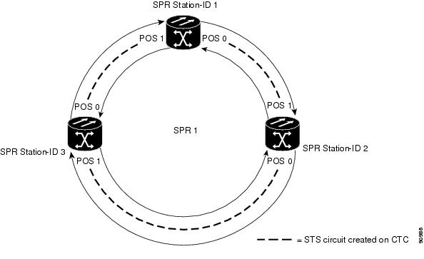
図17-5 の 3 つのノードの RPR は、RPR の連続した手順のすべての例に使用します。これらの例を組み合わせると、RPR 作成のエンドツーエンドの例となります。SONET/SDH ノードとそのネットワークはすでにアクティブであると想定します。

回線を設定するには、CTC に次の 3 つの回線を作成します。
•![]() ノード 1 の POS ポート 0 からノード 2 の POS ポート 1 へ回線を作成します。
ノード 1 の POS ポート 0 からノード 2 の POS ポート 1 へ回線を作成します。
•![]() ノード 2 の POS ポート 0 からノード 3 の POS ポート 1 へ回線を作成します。
ノード 2 の POS ポート 0 からノード 3 の POS ポート 1 へ回線を作成します。
•![]() ノード 3 の POS ポート 0 からノード 1 の POS ポート 1 へ回線を作成します。
ノード 3 の POS ポート 0 からノード 1 の POS ポート 1 へ回線を作成します。
ステップ 1![]() CTC では、ノード 1 にログインして、RPR 内に存在する ML シリーズ カードの CTC カード ビューに移動します。
CTC では、ノード 1 にログインして、RPR 内に存在する ML シリーズ カードの CTC カード ビューに移動します。
図17-6 ML シリーズ カードの CTC カード ビュー
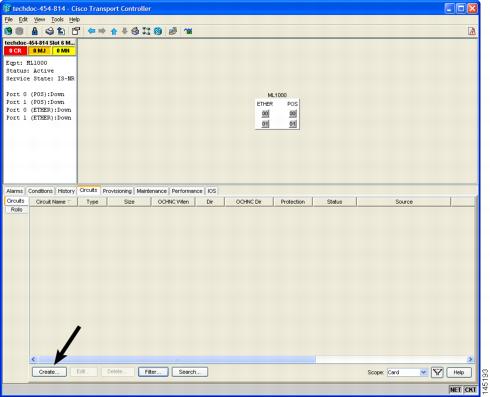
ステップ 2![]() Circuits > Create タブをクリックします。
Circuits > Create タブをクリックします。
Circuit Creation ウィザードの最初のページが表示されます。
図17-7 CTC Circuit Creation ウィザード
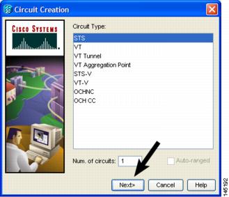
ステップ 3![]() Circuit Type リストで、STS を選択します。
Circuit Type リストで、STS を選択します。
Circuit Attributes ページが表示されます。
ステップ 6![]() Size ドロップダウンリストから該当する回線のサイズを選択し、State リストから適切なステートを選択します。
Size ドロップダウンリストから該当する回線のサイズを選択し、State リストから適切なステートを選択します。
ステップ 7![]() SD スレッシュホールドが SD スレッシュホールド フィールドの 1E-6(デフォルト)または 1E-6 ~ 1E-9 の範囲に設定されていることを確認します。
SD スレッシュホールドが SD スレッシュホールド フィールドの 1E-6(デフォルト)または 1E-6 ~ 1E-9 の範囲に設定されていることを確認します。
a.![]() SD スレッシュホールドがデフォルトの 1E-6 または適切な範囲内である場合は、ステップ 8 へ進みます。
SD スレッシュホールドがデフォルトの 1E-6 または適切な範囲内である場合は、ステップ 8 へ進みます。
b.![]() SD スレッシュホールドがデフォルトの 1E-6 でない場合、または適切な範囲内にない場合は、メニューから 1E-6 または適切な範囲内のスレッシュホールドを選択します。
SD スレッシュホールドがデフォルトの 1E-6 でない場合、または適切な範囲内にない場合は、メニューから 1E-6 または適切な範囲内のスレッシュホールドを選択します。
(注) SD スレッシュホールド値を小さくすると CTC コンバージェンスの速度が速くなりますが、特定の状況ではインターフェイスのフラッピング(イネーブルとディセーブルの繰り返し)の可能性が高くなります。
ステップ 9![]() Node ドロップダウン リストからノード 1 を送信元ノードとして選択します。
Node ドロップダウン リストからノード 1 を送信元ノードとして選択します。
ステップ 10![]() Slot ドロップダウン リストから ML シリーズ カードを選択し、Port ドロップダウン リストから 0(POS)を選択します。
Slot ドロップダウン リストから ML シリーズ カードを選択し、Port ドロップダウン リストから 0(POS)を選択します。
ステップ 12![]() Node ドロップダウン リストからノード 2 を宛先ノードとして選択します。
Node ドロップダウン リストからノード 2 を宛先ノードとして選択します。
ステップ 13![]() Slot ドロップダウン リストから ML シリーズ カードを選択し、Port ドロップダウン リストから 1(POS)を選択します。
Slot ドロップダウン リストから ML シリーズ カードを選択し、Port ドロップダウン リストから 1(POS)を選択します。
Circuit Routing Preferences ページが表示されます。
ステップ 15![]() Fully Protected Path チェック ボックスをオフにします。
Fully Protected Path チェック ボックスをオフにします。
Circuit Constraints for Automatic Routing ページが表示されます。
ステップ 17![]() ノード 1 アイコンをクリックして選択し、Next をクリックします。
ノード 1 アイコンをクリックして選択し、Next をクリックします。
(注) 回線を作成すると、TPTFAIL アラームが CTC に表示される場合があります。POS ポートを 「ML シリーズ カードの POS ポートの SPR インターフェイスへの割り当て」 の手順でイネーブルにすると、このアラームは消えます。
ステップ 19![]() 2 番めの回線をノード 2 の POS 0 とノード 3 の POS 1 の間に作成します。ステップ 1 ~ 18 と同じ手順を使用します。ただし、ノード 1 をノード 2 に、ノード 2 をノード 3 に置き換えます。
2 番めの回線をノード 2 の POS 0 とノード 3 の POS 1 の間に作成します。ステップ 1 ~ 18 と同じ手順を使用します。ただし、ノード 1 をノード 2 に、ノード 2 をノード 3 に置き換えます。
ステップ 20![]() 3 番めの回線をノード 3 の POS 0 とノード 1 の POS 1 の間に作成します。ステップ 1 ~ 18 と同じ手順を使用します。ただし、ノード 1 をノード 3 に、ノード 2 をノード 1 に置き換えます。
3 番めの回線をノード 3 の POS 0 とノード 1 の POS 1 の間に作成します。ステップ 1 ~ 18 と同じ手順を使用します。ただし、ノード 1 をノード 3 に、ノード 2 をノード 1 に置き換えます。
これにより、3 つのノードの POS ポートすべてが STS ポイントツーポイント回線によってイーストからウェストのパターンで接続されました(図17-5 を参照)。
ML シリーズ カード上の RPR 特性と SPR インターフェイスの設定
ML シリーズ カードで RPR を設定するには、Cisco IOS の CLI(コマンドライン インターフェイス)から SPR インターフェイスを作成します。SPR インターフェイスは SPR の仮想インターフェイスです。1 枚の ML シリーズ カードは単一の MAC アドレスを持つ 1 つの SPR インターフェイスをサポートします。SPR インターフェイスは、デフォルト ルートのサポートなど、Cisco IOS インターフェイスの通常のすべての属性を提供します。
SPR インターフェイスは、EtherChannel(ポートチャネル)インターフェイスと同様に設定されます。channel-group コマンドを使用してメンバーを定義するのではなく、spr-intf-ID コマンドを使用します。ポートチャネルと同様に、物理 POS インターフェイスの代わりに仮想 SPR インターフェイスを設定します。SPR インターフェイスはトランク ポートとみなされるため、すべてのトランク ポートと同様に、SPR インターフェイスがブリッジ グループに加入するようにサブインターフェイスを設定する必要があります。
ML シリーズ カードの物理 POS インターフェイスは、SPR インターフェイスに適した唯一のメンバーです。一方の POS ポートはノードから東方向にリングを回る SONET/SDH 回線と関連付けられ、もう一方の POS ポートは西方向の回線に関連付けられています。SPR インターフェイスを使用し、POS ポートが関連付けられている場合、RPR カプセル化を SONET/SDH ペイロードで使用します。
(注) ML シリーズ カードの RPR はデフォルトの LEX カプセル化でのみサポートされています。これは、Cisco ONS イーサネット ライン カードで使用される特別な CISCO-EOS-LEX カプセル化方式です。
RPR は、RPR 内に存在する各 ML シリーズ カード上でプロビジョニングする必要があります。RPR を設定するには、グローバル コンフィギュレーション モードで次の手順を実行します。
ML シリーズ カードの POS ポートの SPR インターフェイスへの割り当て
RPR で使用するために、POS ポートは LEX カプセル化を必要とします。RPR 設定の最初のステップは、POS 0 ポートと POS 1 ポートのカプセル化を LEX に設定することです。
また、ML シリーズ カードの 2 つの POS ポートをそれぞれ SPR インターフェイスに割り当てる必要があります。LEX カプセル化を設定し、ML シリーズ カードの POS インターフェイスを SPR に割り当てるには、グローバル コンフィギュレーション モードで次の手順を実行します。
|
|
|
|
|---|---|---|
|
|
インターフェイス コンフィギュレーション モードを開始し、SPR に割り当てる 1 つめの POS インターフェイスを設定します。 |
|
|
|
POS インターフェイスのカプセル化を LEX として設定します(デフォルト)。ML シリーズ カードの RPR では、LEX カプセル化が必要です。 |
|
|
|
POS インターフェイスを SPR インターフェイスに割り当てます。共有パケット リング番号は1 である必要があります。この番号は、SPR インターフェイスに割り当てられる唯一の共有パケット リング番号です。 |
|
|
|
(任意)キャリア遅延時間を設定します。デフォルトの設定は、200 ミリ秒です。これは、SONET/SDH 保護回線に最適な時間です。
(注) キャリア遅延時間の設定に使用するデフォルトの時間単位は秒です。msec コマンドは、時間単位をミリ秒にリセットします。 |
|
|
|
(任意)SONET/SDH ビット エラー レートが信号劣化アラームに設定されているスレッシュホールドを超えたときに、POS インターフェイスがダウンするようにトリガーを設定します。POS インターフェイスがダウンすると、RPR ラップを開始します。 過度の SONET/SDH ビット エラーにより RPR トラフィックでパケット損失が発生する可能性があるため、すべての RPR POS インターフェイスに対してこのコマンドを使用することを推奨します。
(注) Cisco ONS 15310がリングの一部である場合、このコマンドを使用しないでください。RPR ラッピングが矛盾する可能性があります。 |
|
|
|
||
|
|
インターフェイス コンフィギュレーション モードを開始し、SPR に割り当てる 2 つめの POS インターフェイスを設定します。 |
|
|
|
POS インターフェイスのカプセル化を LEX として設定します(デフォルト)。ML シリーズ カードの RPR では、LEX カプセル化が必要です。 |
|
|
|
POS インターフェイスを SPR インターフェイスに割り当てます。共有パケット リング番号は 1 である必要があります(ステップ 3 で割り当てた共有パケット リング番号と同じ番号)。この番号は、SPR インターフェイスに割り当てられる唯一の共有パケット リング番号です。 |
|
|
|
(任意)キャリア遅延時間を設定します。デフォルトの設定は、200 ミリ秒です。これは、SONET/SDH 保護回線に最適な時間です。 |
|
|
|
(任意)SONET/SDH ビット エラー レートが信号劣化アラームに設定されているスレッシュホールドを超えたときに、POS インターフェイスがダウンするようにトリガーを設定します。POS インターフェイスがダウンすると、RPR ラップを開始します。 過度の SONET/SDH ビット エラーにより RPR トラフィックでパケット損失が発生する可能性があるため、すべての RPR POS インターフェイスに対してこのコマンドを使用することを推奨します。 |
|
|
|
||
|
|
||
|
|
ブリッジ グループの作成とイーサネットおよび SPR インターフェイスの割り当て
ML シリーズ カードのデフォルト動作では、インターフェイスがイネーブルであってもトラフィックは RPR 上でブリッジされません。これは、Cisco Catalyst 6500 や Cisco Catalyst 7600 を含めた多くのレイヤ 2 スイッチとは対照的です。これらのスイッチはデフォルトでは VLAN 1 を転送します。ML シリーズ カードは、タグなしパケットまたは VLAN 1 タグ付きパケットを含め、デフォルトではトラフィックを転送しません。
ML シリーズ カードでブリッジされる RPR トラフィックの場合、そのトラフィック用にブリッジ グループを作成する必要があります。ブリッジ グループは ML シリーズ カードのインターフェイス間でブリッジングおよび転送を維持するので、ローカルでは重要です。ブリッジ グループに参加していないインターフェイスは、ブリッジッド トラフィックを転送できません。
RPR 用のブリッジ グループを作成するには、同じブリッジ グループ内に含める必要のあるイーサネット インターフェイスを決定し、ブリッジ グループを作成し、これらのインターフェイスとブリッジ グループを関連付けます。次に、RPR インフラストラクチャ上での転送を行うため、SPR インターフェイスおよび同じブリッジ グループを関連付けます。
図17-8 に、RPR の SPR 仮想インターフェイスを含めた ML シリーズ カード インターフェイスをスパニングするブリッジ グループを示します。
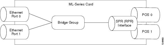
必要なインターフェイスを設定するには、グローバル コンフィギュレーション モードで次の手順を実行します。
RPR Cisco IOS の設定例
図17-5 に、RPR Cisco IOS の完全な設定例を示します。関連する Cisco IOS コードは、 17-1 、 17-2 、 17-3 に示します。この設定は、ML シリーズ カードの POS ポートが、CTC から設定されたポイントツーポイント SONET/SDH 回線によって、すでにリンクされていることを前提としています。
RPR イーサネット アクセス ポート間のイーサネット接続の確認
RPR のプロビジョニング手順が終了したあと、標準イーサネット接続テストを使用して、個別の ML シリーズ カード上の イーサネット アクセス ポート間のイーサネット接続をテストします。
RPR のモニタリングおよび確認
RPR を設定したあと、 show interface spr 1 コマンド (例17-4)または show run interface spr 1 コマンド(例17-5)を使用して、RPR のステータスをモニタリングできます。
例17-4 show interface spr 1 の出力例
例17-5 show run interface spr 1 の出力例
ML シリーズ カードの RPR への追加
既存の RPR は、ML シリーズ カードを追加する必要があります。RPR ラッピング機能とリング アーキテクチャにより、データ トラフィックをダウンさせることなく、追加できます。ML シリーズ カードは、カードを含んだノードを含んだリードとともに、基盤となる SONET/SDH アーキテクチャに追加できます。すでに SONET/SDH トポロジーの一部であるノードに、ML シリーズ カードを追加することもできます。
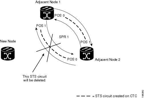
次の例では、ML シリーズ カードを接続する 2 つの STS 回線を持った 2 ノードの RPR の例を示します。回線の 1 つは削除されます。RPR は、ping 損失を最小限にして、残りの回線上でトラフィックをラップします。そのあと 3 番めのノードと ML シリーズ カードが追加され、このカード用にスパンと回線が作成されます。
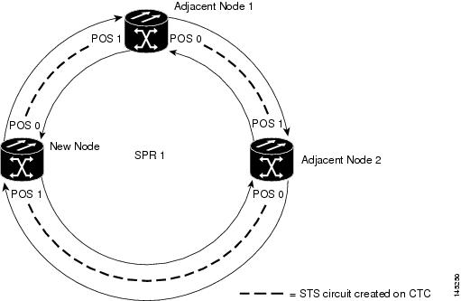
図17-9 に、削除される単一 STS 回線とスパンを持った既存の 2 ノードの RPR を示します。図17-10 に、追加される新しい 2 つの STS 回線、およびスパンが 3 番めのノードに追加されたあとの RPR を示します。
ML シリーズ カードを RPR に追加するには、次の一般的な手順を実行する必要があります。
•![]() 削除するスパンを使用する既存の非 ML シリーズ カード回線(DS-1 など)を遠ざけます。
削除するスパンを使用する既存の非 ML シリーズ カード回線(DS-1 など)を遠ざけます。
•![]() RPR ラップを開始するため、削除する STS 回線の隣接する ML シリーズ カードの POS ポートをシャットダウンします。
RPR ラップを開始するため、削除する STS 回線の隣接する ML シリーズ カードの POS ポートをシャットダウンします。
•![]() RPR ラップが正常に行われたことを確認するため、テスト セットを使用して、既存の隣接 ML シリーズ カードのアクセス ポート間のイーサネット接続をテストします。
RPR ラップが正常に行われたことを確認するため、テスト セットを使用して、既存の隣接 ML シリーズ カードのアクセス ポート間のイーサネット接続をテストします。
•![]() 新しい回線で置き換えられる STS 回線を削除します(図17-9 では、POS 0 の隣接ノード 2 と POS 1 の隣接ノード 1 間の回線です)。
新しい回線で置き換えられる STS 回線を削除します(図17-9 では、POS 0 の隣接ノード 2 と POS 1 の隣接ノード 1 間の回線です)。
•![]() ノードがトポロジーの一部ではない場合、新しいノードをリング トポロジーに接続します。
ノードがトポロジーの一部ではない場合、新しいノードをリング トポロジーに接続します。
•![]() ML シリーズ カードを接続し、初期コンフィギュレーション ファイルをロードするか、またはML シリーズ カードを初期設定します。
ML シリーズ カードを接続し、初期コンフィギュレーション ファイルをロードするか、またはML シリーズ カードを初期設定します。
•![]() POS ポートを手動でイネーブルにするか、またはコンフィギュレーション ファイルを介してイネーブルにする前に、新しいノードに RPR が設定されていることを確認してください。
POS ポートを手動でイネーブルにするか、またはコンフィギュレーション ファイルを介してイネーブルにする前に、新しいノードに RPR が設定されていることを確認してください。
•![]() 既存の隣接 ML シリーズ カードの POS ポートの 1 つから、新しい ML シリーズ カードの POS ポートへの STS 回線を作成します(図17-10 では、POS ポート 0 の隣接ノード 2 と POS ポート 1 の新しいノード間の回線です)。
既存の隣接 ML シリーズ カードの POS ポートの 1 つから、新しい ML シリーズ カードの POS ポートへの STS 回線を作成します(図17-10 では、POS ポート 0 の隣接ノード 2 と POS ポート 1 の新しいノード間の回線です)。
•![]() 別の既存の隣接 ML シリーズ カードの POS ポートの 1 つから、新しい ML シリーズ カードの残りの POS ポートへの 2 番めの STS 回線を作成します(図17-10 では、POS ポート 0 の新しいノードと POS ポート 1 の隣接ノード 1 間の回線です)。
別の既存の隣接 ML シリーズ カードの POS ポートの 1 つから、新しい ML シリーズ カードの残りの POS ポートへの 2 番めの STS 回線を作成します(図17-10 では、POS ポート 0 の新しいノードと POS ポート 1 の隣接ノード 1 間の回線です)。
•![]() 初期コンフィギュレーション ファイルが RPR に参加し、POS ポートをイネーブルにしなかった場合、新しい ML シリーズ カードがこれを実行するよう設定します。
初期コンフィギュレーション ファイルが RPR に参加し、POS ポートをイネーブルにしなかった場合、新しい ML シリーズ カードがこれを実行するよう設定します。
•![]() 新しい ML シリーズ カードに接続された既存の隣接 ML シリーズ カード上で POS ポートをイネーブルにします(図17-10 では、POS ポート 1 の隣接ノード 1 と POS ポート 0 の隣接ノード 2 です)。
新しい ML シリーズ カードに接続された既存の隣接 ML シリーズ カード上で POS ポートをイネーブルにします(図17-10 では、POS ポート 1 の隣接ノード 1 と POS ポート 0 の隣接ノード 2 です)。
•![]() 新しく作成された 3 ノードの RPR を検証するため、テスト セットを使用して、新しい ML シリーズ カードのアクセス ポート間のイーサネット接続をテストします。
新しく作成された 3 ノードの RPR を検証するため、テスト セットを使用して、新しい ML シリーズ カードのアクセス ポート間のイーサネット接続をテストします。
•![]() ノードの挿入後、最低 1 時間以上は、イーサネット トラフィックと既存のルーティング プロトコルをモニタリングします。
ノードの挿入後、最低 1 時間以上は、イーサネット トラフィックと既存のルーティング プロトコルをモニタリングします。
ML シリーズ カードの RPR への追加
ML シリーズ カードを例に示す RPR に追加するには、次の手順を実行します。
ステップ 1![]() 最初の隣接ノードの ML シリーズ カードの Cisco IOS CLI セッションを開始します。これは、図17-9 の隣接ノード 1 です。
最初の隣接ノードの ML シリーズ カードの Cisco IOS CLI セッションを開始します。これは、図17-9 の隣接ノード 1 です。
ステップ 2![]() グローバル コンフィギュレーション モードを開始して、最初の隣接ノードの ML シリーズ カード上で次の Cisco IOS コンフィギュレーションを完了します。
グローバル コンフィギュレーション モードを開始して、最初の隣接ノードの ML シリーズ カード上で次の Cisco IOS コンフィギュレーションを完了します。
|
|
削除する回線の 1 つのエンドポイントで、POS ポートのインターフェイス コンフィギュレーション モードを開始します。 |
|
ステップ 3![]() 図17-9 で示す隣接ノード 2 の ML シリーズ カードの Cisco IOS CLI セッションを開始します。
図17-9 で示す隣接ノード 2 の ML シリーズ カードの Cisco IOS CLI セッションを開始します。
ステップ 4![]() グローバル コンフィギュレーション モードを開始して、隣接ノード 2 の ML シリーズ カード上で次の Cisco IOS コンフィギュレーションを完了します。
グローバル コンフィギュレーション モードを開始して、隣接ノード 2 の ML シリーズ カード上で次の Cisco IOS コンフィギュレーションを完了します。
|
|
削除する回線の 1 つのエンドポイントで、POS ポートのインターフェイス コンフィギュレーション モードを開始します。 |
|
ステップ 5![]() CTC で、隣接ノード 1 にログインします。
CTC で、隣接ノード 1 にログインします。
ステップ 6![]() 隣接ノード 1 の ML シリーズ カードをダブルクリックします。
隣接ノード 1 の ML シリーズ カードをダブルクリックします。
ステップ 9![]() 削除する回線のエンドポイントで POS ポートと一致する回線エントリの送信元カラムと宛先カラムを参照して、適切な STS 回線を特定します。
削除する回線のエンドポイントで POS ポートと一致する回線エントリの送信元カラムと宛先カラムを参照して、適切な STS 回線を特定します。
回線エントリは、Node-1/s12(ML100T)/pPOS-0 などのように node-name/card-slot/port-number 形式になっています。
ステップ 10![]() ハイライトする回線エントリをクリックします。
ハイライトする回線エントリをクリックします。
confirmation ダイアログ ボックスが表示されます。
ステップ 13![]() テスト セットを使用して、隣接ノード 1 のイーサネット アクセス ポートと隣接ノード 2 のイーサネット アクセス ポート間にイーサネット接続がまだ存在するかどうかを確認します。
テスト セットを使用して、隣接ノード 1 のイーサネット アクセス ポートと隣接ノード 2 のイーサネット アクセス ポート間にイーサネット接続がまだ存在するかどうかを確認します。
(注) ML シリーズ カードの SPR インターフェイスおよびイーサネット インターフェイスは、RPR トラフィックが RPR をブリッジングするため、ブリッジ グループに存在する必要があります。
ステップ 14![]() 新しいノードが SONET/SDH リング トポロジーでまだアクティブ ノードではない場合、ノードをリングに追加します。ONS ノードの設置手順については、『 Cisco ONS 15454 Procedure Guide』の「Add and Remove Nodes」 の章、または『 Cisco ONS 15454 SDH Procedure Guide』の「Add and Remove Nodes」の章を参照してください。
新しいノードが SONET/SDH リング トポロジーでまだアクティブ ノードではない場合、ノードをリングに追加します。ONS ノードの設置手順については、『 Cisco ONS 15454 Procedure Guide』の「Add and Remove Nodes」 の章、または『 Cisco ONS 15454 SDH Procedure Guide』の「Add and Remove Nodes」の章を参照してください。
ステップ 15![]() 新しいノードの ML シリーズ カードがまだ取り付けられていない場合、新しいカードをそのノードに取り付けます。カードの ONS ノードへの取り付け手順については、『 Cisco ONS 15454 Procedure Guide』 の「Install Cards and Fiber-Optic Cable」の章、または『 Cisco ONS 15454 SDH Procedure Guide』の「Install Cards and Fiber-Optic Cable」の章を参照してください。
新しいノードの ML シリーズ カードがまだ取り付けられていない場合、新しいカードをそのノードに取り付けます。カードの ONS ノードへの取り付け手順については、『 Cisco ONS 15454 Procedure Guide』 の「Install Cards and Fiber-Optic Cable」の章、または『 Cisco ONS 15454 SDH Procedure Guide』の「Install Cards and Fiber-Optic Cable」の章を参照してください。
ステップ 16![]() 新しい ML シリーズ カードの初期スタートアップ コンフィギュレーション ファイルをアップロードします( CTC での Cisco IOS スタートアップ コンフィギュレーション ファイルのロード を参照)。スタートアップ コンフィギュレーション ファイルの準備ができていない場合、「シリアル コンソール ポートを使用して手動でスタートアップ コンフィギュレーション ファイルを作成する方法」 を参照してください。
新しい ML シリーズ カードの初期スタートアップ コンフィギュレーション ファイルをアップロードします( CTC での Cisco IOS スタートアップ コンフィギュレーション ファイルのロード を参照)。スタートアップ コンフィギュレーション ファイルの準備ができていない場合、「シリアル コンソール ポートを使用して手動でスタートアップ コンフィギュレーション ファイルを作成する方法」 を参照してください。
ステップ 17![]() 回線ステートが In-Service(IS)である STS 回線を、隣接ノード 1 の利用可能な POS ポートから新しいノードに作成します(図17-10 を参照)。新しいノードでは、隣接ノード 1 の利用可能な POS ポートのインターフェイス番号と一致しないインターフェイス番号の付いた POS ポートを使用します。たとえば、隣接ノード 1 の POS ポート 0 は新しいノードの POS ポート 1 に接続します。
回線ステートが In-Service(IS)である STS 回線を、隣接ノード 1 の利用可能な POS ポートから新しいノードに作成します(図17-10 を参照)。新しいノードでは、隣接ノード 1 の利用可能な POS ポートのインターフェイス番号と一致しないインターフェイス番号の付いた POS ポートを使用します。たとえば、隣接ノード 1 の POS ポート 0 は新しいノードの POS ポート 1 に接続します。
回線接続手順の詳細については、「RPR の CTC 回線の設定」 を参照してください。
(注) 最良の方法は、イーストからウェスト、またはウェストからイーストに SONET/SDH 回線を設定することです。つまり、SONET/SDH リングで、ポート 0(イースト)からポート 1(ウェスト)、またはポート 1(ウェスト)からポート 0(イースト)のように設定します。
ステップ 18![]() 回線ステートが IS である STS 回線を、隣接ノード 2 の利用可能な POS ポートから新しいノーの残りの POS ポートに作成します(図17-10 を参照)。
回線ステートが IS である STS 回線を、隣接ノード 2 の利用可能な POS ポートから新しいノーの残りの POS ポートに作成します(図17-10 を参照)。
ステップ 19![]() 図17-9 で示す隣接ノード 1 の ML シリーズ カードの Cisco IOS CLI セッションを開始または再開します。
図17-9 で示す隣接ノード 1 の ML シリーズ カードの Cisco IOS CLI セッションを開始または再開します。
ステップ 20![]() グローバル コンフィギュレーション モードを開始して、次の Cisco IOS コンフィギュレーションを完了します。
グローバル コンフィギュレーション モードを開始して、次の Cisco IOS コンフィギュレーションを完了します。
|
|
新しく最初に作成した回線の 1 つのエンドポイントで、POS ポートのインターフェイス コンフィギュレーション モードを開始します。 |
|
ステップ 21![]() 図17-9 で示す隣接ノード 2 の ML シリーズ カードの Cisco IOS CLI セッションを開始します。
図17-9 で示す隣接ノード 2 の ML シリーズ カードの Cisco IOS CLI セッションを開始します。
ステップ 22![]() グローバル コンフィギュレーション モードを開始して、隣接ノード 2 の ML シリーズ カード上で次の Cisco IOS コンフィギュレーションを完了します。
グローバル コンフィギュレーション モードを開始して、隣接ノード 2 の ML シリーズ カード上で次の Cisco IOS コンフィギュレーションを完了します。
|
|
新しく 2 番めに作成した回線の 1 つのエンドポイントで、POS ポートのインターフェイス コンフィギュレーション モードを開始します。 |
|
ステップ 23![]() イーサネット接続が RPR に存在するかどうか確認するため、テスト セットを使用します。
イーサネット接続が RPR に存在するかどうか確認するため、テスト セットを使用します。
ステップ 24![]() ノードの挿入後、最低 1 時間以上は、イーサネット トラフィックとルーティング テーブルをモニタリングします。
ノードの挿入後、最低 1 時間以上は、イーサネット トラフィックとルーティング テーブルをモニタリングします。
RPR からの ML シリーズ カードの削除
既存の RPR は、ML シリーズ カードを削除する必要があります。RPR ラッピング機能とリング アーキテクチャにより、データ トラフィックをダウンさせることなく、削除できます。
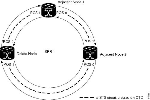
次の例では、ML シリーズ カードを接続する 3 つの STS 回線を持った 3 ノードの RPR の例を示します。回線の 2 つは削除されます。RPR は、ping 損失を最小限にして、残りの回線でトラフィックをラップします。そのあと、3 番めのノードと ML シリーズ カードは削除され、新しい STS 回線が残りのカード間に作成されます。
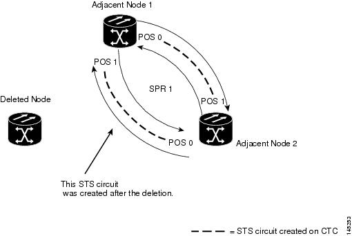
図17-11 に、3 つの STS 回線とスパンを持った既存の 3 ノードの RPR を示します。図17-12 に、3 番めのノード、回線、スパンが削除され、新しい STS 回線が追加されたあとの RPR を示します。
ML シリーズ カードを RPR から削除するには、次の一般的な手順を実行する必要があります。
•![]() 削除するスパンを使用する既存の非 ML シリーズ カード回線(DS-1 など)を遠ざけます。
削除するスパンを使用する既存の非 ML シリーズ カード回線(DS-1 など)を遠ざけます。
•![]() RPR ラップを開始するため、削除する STS 回線の隣接する ML シリーズ カードの POS ポートをシャットダウンします。
RPR ラップを開始するため、削除する STS 回線の隣接する ML シリーズ カードの POS ポートをシャットダウンします。
•![]() RPR ラップが正常に行われたことを確認するため、テスト セットを使用して、既存の隣接 ML シリーズ カードのアクセス ポート間のイーサネット接続をテストします。
RPR ラップが正常に行われたことを確認するため、テスト セットを使用して、既存の隣接 ML シリーズ カードのアクセス ポート間のイーサネット接続をテストします。
•![]() 新しい回線で置き換えられる 2 つの STS 回線を削除します(図17-11 では、削除ノードと隣接ノード間の回線および削除ノードと別の隣接ノード間の回線です)。
新しい回線で置き換えられる 2 つの STS 回線を削除します(図17-11 では、削除ノードと隣接ノード間の回線および削除ノードと別の隣接ノード間の回線です)。
•![]() 必要に応じて、リング トポロジーから削除ノードを削除します。
必要に応じて、リング トポロジーから削除ノードを削除します。
•![]() 必要に応じて、ノードから削除 ML シリーズ カードを物理的に取り外します。
必要に応じて、ノードから削除 ML シリーズ カードを物理的に取り外します。
•![]() 残りの隣接 ML シリーズ カードのうちの 1 枚の利用可能な POS ポートから、別の残りの隣接 ML シリーズ カードの利用可能な POS ポートへ STS 回線を作成します(図17-12 では、POS ポート 0 の隣接ノード 2 と POS ポート 1 の隣接ノード 1 間の回線です)。
残りの隣接 ML シリーズ カードのうちの 1 枚の利用可能な POS ポートから、別の残りの隣接 ML シリーズ カードの利用可能な POS ポートへ STS 回線を作成します(図17-12 では、POS ポート 0 の隣接ノード 2 と POS ポート 1 の隣接ノード 1 間の回線です)。
•![]() 既存の隣接 ML シリーズ カードの POS ポートをイネーブルにします(図17-12 では、POS ポート 0 の隣接ノード 2 と POS ポート 1 の隣接ノード 1 です)。
既存の隣接 ML シリーズ カードの POS ポートをイネーブルにします(図17-12 では、POS ポート 0 の隣接ノード 2 と POS ポート 1 の隣接ノード 1 です)。
•![]() 2 ノードの RPR を検証するため、テスト セットを使用して、隣接 ML シリーズ カードのアクセス ポート間のイーサネット接続をテストします。
2 ノードの RPR を検証するため、テスト セットを使用して、隣接 ML シリーズ カードのアクセス ポート間のイーサネット接続をテストします。
•![]() ノードの削除後、最低 1 時間以上は、イーサネット トラフィックと既存のルーティング プロトコルをモニタリングします。
ノードの削除後、最低 1 時間以上は、イーサネット トラフィックと既存のルーティング プロトコルをモニタリングします。
RPR からの ML シリーズ カードの削除
RPR から ML シリーズ カードを 削除するには、次の手順を実行します。
ステップ 1![]() 最初の隣接ノードの ML シリーズ カードの Cisco IOS CLI セッションを開始します。これは、図17-11 の隣接ノード 1 です。
最初の隣接ノードの ML シリーズ カードの Cisco IOS CLI セッションを開始します。これは、図17-11 の隣接ノード 1 です。
ステップ 2![]() グローバル コンフィギュレーション モードを開始して、最初の隣接ノードの ML シリーズ カード上で次の Cisco IOS コンフィギュレーションを完了します。
グローバル コンフィギュレーション モードを開始して、最初の隣接ノードの ML シリーズ カード上で次の Cisco IOS コンフィギュレーションを完了します。
|
|
回線の最後で削除ノードに直接接続されている POS ポートのインターフェイス コンフィギュレーション モードを開始します。 |
|
ステップ 3![]() 図17-11 で示す隣接ノード 2 の ML シリーズ カードの Cisco IOS CLI セッションを開始します。
図17-11 で示す隣接ノード 2 の ML シリーズ カードの Cisco IOS CLI セッションを開始します。
ステップ 4![]() グローバル コンフィギュレーション モードで、隣接ノード 2 の ML シリーズ カード上で次の Cisco IOS コンフィギュレーションを完了します。
グローバル コンフィギュレーション モードで、隣接ノード 2 の ML シリーズ カード上で次の Cisco IOS コンフィギュレーションを完了します。
|
|
回線の最後で削除ノードに直接接続されている POS ポートのインターフェイス コンフィギュレーション モードを開始します。 |
|
ステップ 5![]() CTC を使用して隣接ノード 1 にログインします。
CTC を使用して隣接ノード 1 にログインします。
ステップ 6![]() 隣接ノード 1 の ML シリーズ カードをダブルクリックします。
隣接ノード 1 の ML シリーズ カードをダブルクリックします。
ステップ 9![]() 最初に削除する回線のエンドポイントで POS ポートと一致する回線エントリの送信元カラムと宛先カラムを参照して、適切な STS 回線を特定します。
最初に削除する回線のエンドポイントで POS ポートと一致する回線エントリの送信元カラムと宛先カラムを参照して、適切な STS 回線を特定します。
回線エントリは、Node-1/s12(ML100T)/pPOS-0 などのように node-name/card-slot/port-number 形式になっています。
ステップ 10![]() ハイライトする回線エントリをクリックします。
ハイライトする回線エントリをクリックします。
confirmation ダイアログ ボックスが表示されます。
ステップ 13![]() テスト セットを使用して、隣接ノード 1 のイーサネット アクセス ポートと隣接ノード 2 のイーサネット アクセス ポートの間にイーサネット接続がまだ存在するかどうかを確認します。
テスト セットを使用して、隣接ノード 1 のイーサネット アクセス ポートと隣接ノード 2 のイーサネット アクセス ポートの間にイーサネット接続がまだ存在するかどうかを確認します。
(注) ML シリーズ カードの SPR インターフェイスおよびイーサネット インターフェイスは、RPR トラフィックが RPR をブリッジングするため、ブリッジ グループに存在する必要があります。
ステップ 14![]() CTC を使用して隣接ノード 2 にログインします。
CTC を使用して隣接ノード 2 にログインします。
ステップ 15![]() 隣接ノード 2 の ML シリーズ カードをダブルクリックします。
隣接ノード 2 の ML シリーズ カードをダブルクリックします。
ステップ 17![]() Circuits サブタブをクリックします。
Circuits サブタブをクリックします。
ステップ 18![]() 2 番めに削除する回線のエンドポイントで POS ポートと一致する回線エントリの送信元カラムと宛先カラムを参照して、適切な STS 回線を特定します。
2 番めに削除する回線のエンドポイントで POS ポートと一致する回線エントリの送信元カラムと宛先カラムを参照して、適切な STS 回線を特定します。
回線エントリは、Node-1/s12(ML100T)/pPOS-0 などのように node-name/card-slot/port-number 形式になっています。
ステップ 19![]() ハイライトする回線エントリをクリックします。
ハイライトする回線エントリをクリックします。
confirmation ダイアログ ボックスが表示されます。
ステップ 22![]() 新しいノードが SONET/SDH リング トポロジーでアクティブ ノードにならない場合、ノードをリングから削除します。ONS ノードの削除手順については、『 Cisco ONS 15454 Procedure Guide』の「Add and Remove Nodes」 の章、または『 Cisco ONS 15454 SDH Procedure Guide』の「Add and Remove Nodes」の章を参照してください。
新しいノードが SONET/SDH リング トポロジーでアクティブ ノードにならない場合、ノードをリングから削除します。ONS ノードの削除手順については、『 Cisco ONS 15454 Procedure Guide』の「Add and Remove Nodes」 の章、または『 Cisco ONS 15454 SDH Procedure Guide』の「Add and Remove Nodes」の章を参照してください。
ステップ 23![]() 新しいノードの ML シリーズ カードを CTC で削除し、物理的に取り外す必要がある場合は、そのようにしてください。カードの ONS ノードへの取り付け手順については、『 Cisco ONS 15454 Procedure Guide』 の「Install Cards and Fiber-Optic Cable」の章、または『 Cisco ONS 15454 SDH Procedure Guide』の「Install Cards and Fiber-Optic Cable」の章を参照してください。
新しいノードの ML シリーズ カードを CTC で削除し、物理的に取り外す必要がある場合は、そのようにしてください。カードの ONS ノードへの取り付け手順については、『 Cisco ONS 15454 Procedure Guide』 の「Install Cards and Fiber-Optic Cable」の章、または『 Cisco ONS 15454 SDH Procedure Guide』の「Install Cards and Fiber-Optic Cable」の章を参照してください。
ステップ 24![]() 回線ステートが IS である STS 回線を、隣接ノード 1 の利用可能な POS ポートから隣接ノード 2 の利用可能な POS ポートに作成します(図17-12 を参照)。回線接続手順の詳細については、「RPR の CTC 回線の設定」 を参照してください。
回線ステートが IS である STS 回線を、隣接ノード 1 の利用可能な POS ポートから隣接ノード 2 の利用可能な POS ポートに作成します(図17-12 を参照)。回線接続手順の詳細については、「RPR の CTC 回線の設定」 を参照してください。
(注) 最良の方法は、イーストからウェスト、またはウェストからイーストに SONET/SDH 回線を設定することです。つまり、SONET/SDH リングで、ポート 0(イースト)からポート 1(ウェスト)、またはポート 1(ウェスト)からポート 0(イースト)のように設定します。
ステップ 25![]() 隣接ノード 1 の ML シリーズ カードの Cisco IOS CLI セッションを開始または再開します。
隣接ノード 1 の ML シリーズ カードの Cisco IOS CLI セッションを開始または再開します。
ステップ 26![]() グローバル コンフィギュレーション モードを開始して、隣接ノード 1 の ML シリーズ カードの次の Cisco IOS コンフィギュレーションを完了します。
グローバル コンフィギュレーション モードを開始して、隣接ノード 1 の ML シリーズ カードの次の Cisco IOS コンフィギュレーションを完了します。
|
|
新しく最初に作成した回線の 1 つのエンドポイントで、POS ポートのインターフェイス コンフィギュレーション モードを開始します。 |
|
ステップ 27![]() 隣接ノード 2 の ML シリーズ カードの Cisco IOS CLI セッションを開始します。
隣接ノード 2 の ML シリーズ カードの Cisco IOS CLI セッションを開始します。
ステップ 28![]() グローバル コンフィギュレーション モードを開始して、隣接ノード 2 の ML シリーズ カード上で次の Cisco IOS コンフィギュレーションを完了します。
グローバル コンフィギュレーション モードを開始して、隣接ノード 2 の ML シリーズ カード上で次の Cisco IOS コンフィギュレーションを完了します。
|
|
新しく 2 番めに作成した回線の 1 つのエンドポイントで、POS ポートのインターフェイス コンフィギュレーション モードを開始します。 |
|
ステップ 29![]() イーサネット接続が RPR に存在するかどうか確認するため、テスト セットを使用します。
イーサネット接続が RPR に存在するかどうか確認するため、テスト セットを使用します。
ステップ 30![]() ノードの削除後、最低 1 時間以上は、イーサネット トラフィックとルーティング テーブルをモニタリングします。
ノードの削除後、最低 1 時間以上は、イーサネット トラフィックとルーティング テーブルをモニタリングします。
RPR LFP の概要
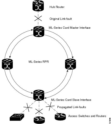
Link Fault Propagation(LFP)は、リンク パススルーとしても知られ、ルータが ML シリーズ カードの RPR で相互接続されているネットワーク内でコンバージェンス時間を短縮します。LFP は、マスター ギガビット イーサネット リンクからギガビット イーサネットやファスト イーサネットのリモート スレーブ リンクへリンク障害をすばやく中継します。LFP により、スレーブ リンクに接続されたルータから代替パスへのフェールオーバーの時間が大幅に改善されます。通常の保護方式では、コンバージェンス時間は 40 秒くらいとなります。LFP を使用すると、スレーブ インターフェイスはマスター インターフェイスの状態を 1 秒未満で反映します。この機能は多くの場合、遠端ハブ サイトのリンク障害をトリガーとして、近端アクセス サイトをリンク ダウン状態にするために使用します。図17-13 に LFP を示します。
LFP シーケンス
LFP の更新は CDP パケット拡張で行われます。更新は定期的に送信されますが、マスター インターフェイスでリンクダウン状態になった場合は、ただちに送信されます。LFP の更新は通常の Cisco Discovery Protocol(CDP)パケットとは別に送信され、これらは互いに影響し合うことはありません。インターフェイス上で CDP を設定したり、ディセーブルにしても LFP の更新には影響しません。
管理上の理由でシャットダウンする場合も含め、マスター インターフェイスがダウンすると、スレーブ インターフェイスが強制的にダウンします。マスター インターフェイスがアップ状態になると、スレーブ インターフェイスもアップ状態に戻ります。スレーブ インターフェイスを管理上の理由でシャットダウンすると、スレーブ インターフェイスで LFP 機能が一時停止します。スレーブ インターフェイスを再度起動すると、LFP 機能が再開します。
マスターからスレーブへの接続で障害があると、スレーブ リンクでもまたリンクのダウン障害が強制的に起こります。接断の原因を次に示します。
•![]() マスターとスレーブ間の両方の RPR パスでのシャットダウンまたは障害
マスターとスレーブ間の両方の RPR パスでのシャットダウンまたは障害
•![]() マスター インターフェイス上での LFP のディセーブル
マスター インターフェイス上での LFP のディセーブル
リンク障害はマスターからスレーブへのみ伝播されます。通常のスレーブのリンク障害は伝播されません。RPR のラッピングとラッピングの解除は LFP には影響しません。
伝播遅延
伝播遅延には、スレーブ インターフェイスでのキャリア遅延時間も含まれます。キャリア遅延時間は設定可能で、そのデフォルト値は 200 ミリ秒です。キャリア遅延時間の設定の詳細については、「RPR の設定」 を参照してください。
伝播遅延にはそれぞれ、異なる LFP のシナリオがあります。
•![]() マスターのリンクダウンとスレーブのリンクダウンの間の伝播遅延は、50 ミリ秒にスレーブ インターフェイスでのキャリア遅延時間を加えたものです。
マスターのリンクダウンとスレーブのリンクダウンの間の伝播遅延は、50 ミリ秒にスレーブ インターフェイスでのキャリア遅延時間を加えたものです。
•![]() マスターのリンクアップとスレーブのリンクアップの間の伝播遅延には、インターフェイスのフラッピングを防止するために、マスター インターフェイスでの組み込み遅延がさらに加わります。リンクアップの伝播には、約 50 ~ 200 ミリ秒とスレーブ インターフェイスでのキャリア遅延時間がかかります。
マスターのリンクアップとスレーブのリンクアップの間の伝播遅延には、インターフェイスのフラッピングを防止するために、マスター インターフェイスでの組み込み遅延がさらに加わります。リンクアップの伝播には、約 50 ~ 200 ミリ秒とスレーブ インターフェイスでのキャリア遅延時間がかかります。
•![]() マスターからスレーブへのリンク障害からスレーブ リンクがダウンするまでの伝播遅延は、約 600 ミリ秒にスレーブ インターフェイスでのキャリア遅延時間を加えたものです。
マスターからスレーブへのリンク障害からスレーブ リンクがダウンするまでの伝播遅延は、約 600 ミリ秒にスレーブ インターフェイスでのキャリア遅延時間を加えたものです。
LFP の設定
図17-13 に LFP を設定した RPR の例を示します。LFP 設定のプロセスは、次のタスクで構成されます。
1.![]() ある ML シリーズ カードのギガビット イーサネット インターフェイスをマスター リンクとして設定します。
ある ML シリーズ カードのギガビット イーサネット インターフェイスをマスター リンクとして設定します。
2.![]() 別の ML シリーズ カードのギガビット イーサネットまたはファスト イーサネット インターフェイスをスレーブ リンクとして設定します。
別の ML シリーズ カードのギガビット イーサネットまたはファスト イーサネット インターフェイスをスレーブ リンクとして設定します。
LFP マスター リンクをイネーブルにして設定するには、グローバル コンフィギュレーション モードで次の手順を実行します。
|
|
|
|
|---|---|---|
interface
gigabit ethernet
number
|
||
|
|
||
no shutdown
|
||
|
|
||
|
|
LFP スレーブ リンクをイネーブルに設定するには、マスター リンク用に設定された ML シリーズ カード以外の、RPR 内の ML シリーズ カードに対して次の手順を実行します。グローバル コンフィギュレーション モードで、次の手順を実行します。
LFP の設定要件
•![]() リンク障害マスターとリンク障害スレーブを同じカード上で設定しない。
リンク障害マスターとリンク障害スレーブを同じカード上で設定しない。
•![]() ML シリーズ カードで拡張マイクロコード イメージを実行する必要がある。
ML シリーズ カードで拡張マイクロコード イメージを実行する必要がある。
•![]() RPR 内のすべての ML シリーズ カードでリリース 5.0 以降のソフトウェアを実行する必要がある。
RPR 内のすべての ML シリーズ カードでリリース 5.0 以降のソフトウェアを実行する必要がある。
•![]() DRPRI 用に設定された ML シリーズ カードは LFP 用に設定しない。DRPRI での LFP はサポートされていない。
DRPRI 用に設定された ML シリーズ カードは LFP 用に設定しない。DRPRI での LFP はサポートされていない。
•![]() ML シリーズ カードのギガビット イーサネット インターフェイスだけがリンク障害マスターになれる。
ML シリーズ カードのギガビット イーサネット インターフェイスだけがリンク障害マスターになれる。
•![]() RPR ごとに許可されているリンク障害マスターは 1 つのみ。
RPR ごとに許可されているリンク障害マスターは 1 つのみ。
•![]() ギガビット イーサネット インターフェイスとファスト イーサネット インターフェイスの両方がリンク障害スレーブになれる。
ギガビット イーサネット インターフェイスとファスト イーサネット インターフェイスの両方がリンク障害スレーブになれる。
LFP のモニタリングおよび確認
リンク ダウン状態のスレーブ インターフェイスがあると、CTC で CARLOSS アラームが発生します。CTC は、スレーブ リンクでのローカルの損失と LFP による損失とを区別しません。CARLOSS の詳細については、『 Cisco ONS 15454 Troubleshooting Guide 』の「Alarm Troubleshooting」の章または 『 Cisco ONS 15454 SDH Troubleshooting Guide 』の「Alarm Troubleshooting」の章を参照してください。
リンク ダウンしているインターフェイスの Cisco IOS ステータスは、プロトコル ダウンまたはリンク ダウンとして表示されます。show controller コマンドでも show interface コマンドでも、リンク上のローカル損失と LFP 損失との違いは表示されません。
LFP を設定したあと、 show link-fault コマンドを使用して各マスター リンクまたはスレーブ リンクの LFP ステータスをモニタリングできます。このコマンドを使用して、LFP が原因でスレーブ インターフェイスでリンク ダウンが発生したかを判別します。例17-6 に、スレーブ インターフェイスでこのコマンドを実行した場合の出力を示します。
デュアル RPR 相互接続の概要
Cisco ML シリーズの RPR には、ブリッジ グループ プロトコル DRPRI が含まれます。これは、ノード障害から保護するためにリング間を相互接続するメカニズムです。DRPRI は、異なる RPR ネットワーク間のバックツーバック イーサネット接続の冗長ペアをサポートします。一方の接続はアクティブ ノードであり、もう一方はスタンバイ ノードです。アクティブ ノード、リンク、またはカードで障害が発生すると、独自のアルゴリズムによって障害が検出され、スタンバイ ノードへのスイッチ オーバーが発生します。
ML シリーズ カードで拡張マイクロ コード イメージを使用している場合は、DRPRI でレイヤ 2 のブリッジド トラフィックに適用される回復時間は 200 ミリ秒未満です。ML シリーズ カードが基本マイクロコード イメージ、または Multiprotocol Label Switching(MPLS; マルチプロトコル ラベル スイッチング)マイクロコード イメージを使用している場合、レイヤ 2 ブリッジド トラフィックの回復時間は最長 12 秒になります。どのマイクロコード イメージを使用している場合でも、レイヤ 3 のユニキャストおよびマルチキャスト トラフィックの回復時間は、実装しているルーティング プロトコルのコンバージェンス時間にも依存します。DRPRI ホップに関係なく、カスタマー ルーティング プロトコルとスパニングツリー インスタンスは接続されません。
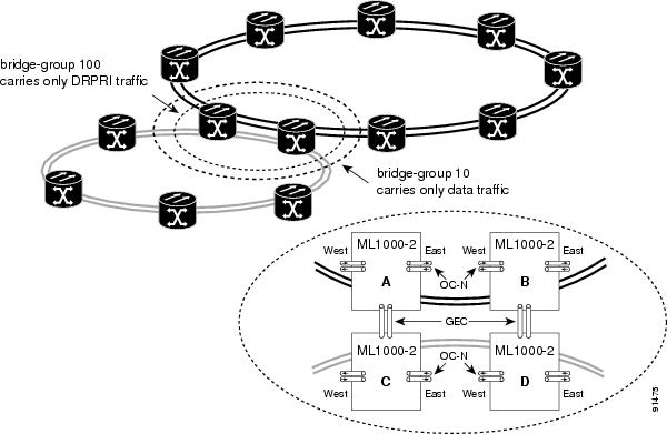
ML1000-2 カードのペアは同じステーション ID を共有し、RPR の他のメンバーには 1 枚のカードとして認識されます。図17-14 では、ペア カード A と B が、同じ SPR ステーション ID を持ち、ペア カード C と D が、同じステーション ID を持ちます。相互接続するノードは、RPR で隣接している必要はありません。ブリッジング、IP ルーティング、ポリシング、および帯域幅割り当ては、DRPRI ML1000-2 カードにもプロビジョニングできます。次の例のブリッジ グループ 100 は DRPRI トラフィックを伝送します。次の例のブリッジ グループ 10 はデータ トラフィックを伝送します。
図17-14 デュアル RPR 相互接続ネットワークとペア カード
•![]() DRPRI ブリッジ グループをデータ トラフィックの伝送に使用することもできません。
DRPRI ブリッジ グループをデータ トラフィックの伝送に使用することもできません。
•![]() DRPRI ブリッジ グループは 1 つのプロトコルに制限されるため、DRPRI を実装しているブリッジ グループは、RSTP や STP を実装することはできません。
DRPRI ブリッジ グループは 1 つのプロトコルに制限されるため、DRPRI を実装しているブリッジ グループは、RSTP や STP を実装することはできません。
•![]() 4 枚の ML1000-2 カードはすべて、同じブリッジ グループ(VLAN)に属している必要があります。
4 枚の ML1000-2 カードはすべて、同じブリッジ グループ(VLAN)に属している必要があります。
•![]() ML1000-2 カードの各ペアは、同じ SPR ステーション ID が割り当てられている必要があります。
ML1000-2 カードの各ペアは、同じ SPR ステーション ID が割り当てられている必要があります。
•![]() ブリッジ グループを SPR サブインターフェイスで設定する必要があります。
ブリッジ グループを SPR サブインターフェイスで設定する必要があります。
•![]() 4 枚の各 ML1000-2 カードで、両方のギガビット イーサネット ポートは、Gigabit EtherChannel(GEC)に加入し、GEC インターフェイスは DRPRI ブリッジ グループに含まれている必要があります。または、一方のギガビット イーサネット ポートをシャットダウンし、もう一方のポートを DRPRI ブリッジ グループに含める必要があります。GEC 方式を推奨します。
4 枚の各 ML1000-2 カードで、両方のギガビット イーサネット ポートは、Gigabit EtherChannel(GEC)に加入し、GEC インターフェイスは DRPRI ブリッジ グループに含まれている必要があります。または、一方のギガビット イーサネット ポートをシャットダウンし、もう一方のポートを DRPRI ブリッジ グループに含める必要があります。GEC 方式を推奨します。
•![]() DRPRI ブリッジ グループに含まれるサブインターフェイスまたは GEC インターフェイス上で手動シャットダウンを行う場合、リング間の GEC またはイーサネット接続の両端のインターフェイスで行う必要があります。
DRPRI ブリッジ グループに含まれるサブインターフェイスまたは GEC インターフェイス上で手動シャットダウンを行う場合、リング間の GEC またはイーサネット接続の両端のインターフェイスで行う必要があります。
•![]() DRPRI ノードを使用できるのは、2 つの RPR を相互接続する場合だけです。カードのフロント ポートを他のトラフィックの伝送に使用しないでください。
DRPRI ノードを使用できるのは、2 つの RPR を相互接続する場合だけです。カードのフロント ポートを他のトラフィックの伝送に使用しないでください。
•![]() リング間でトラフィックを伝送する DRPRI 以外のブリッジ グループでは、STP または RSTP を設定できません。
リング間でトラフィックを伝送する DRPRI 以外のブリッジ グループでは、STP または RSTP を設定できません。
•![]() リング間でトラフィックを伝送する DRPRI 以外のブリッジ グループは、4 枚の各 ML シリーズ カードで設定する必要があります。
リング間でトラフィックを伝送する DRPRI 以外のブリッジ グループは、4 枚の各 ML シリーズ カードで設定する必要があります。
•![]() 802.1 Q トンネル(QinQ)およびプロトコル トンネルを DRPRI ノードで開始することはできませんが、DRPRI ノードは接続されたリング間で QinQ とプロトコル トンネルをブリッジできます。
802.1 Q トンネル(QinQ)およびプロトコル トンネルを DRPRI ノードで開始することはできませんが、DRPRI ノードは接続されたリング間で QinQ とプロトコル トンネルをブリッジできます。
•![]() ユーザが DRPRI ブリッジ グループのメンバーのパス コストを変更してはなりません。パスコストは ML シリーズ カードによって割り当てられ、DRPRI が正常に動作することが保証されます。ユーザが設定したパスコストは、割り当てられた DRPRI のデフォルトのパスコストで上書きされます。
ユーザが DRPRI ブリッジ グループのメンバーのパス コストを変更してはなりません。パスコストは ML シリーズ カードによって割り当てられ、DRPRI が正常に動作することが保証されます。ユーザが設定したパスコストは、割り当てられた DRPRI のデフォルトのパスコストで上書きされます。
DRPRI の設定
DRPRI には、2 組の ML シリーズ カードが必要です。1 組は RPR として設定し、隣接する 2 つの RPR の 1 つめに属します。もう 1 組は RPR として設定し、2 つめの RPR に属します(図17-14)。2 つの隣接する RPR を接続する 4 枚の各 ML1000-2 カードで DRPRI を設定します。DRPRI の設定プロセスのおおまかな手順は次のとおりです。この手順の詳細は、Cisco IOS 手順で説明されています。
ステップ 1![]() DRPRI プロトコルでブリッジ グループを設定します。
DRPRI プロトコルでブリッジ グループを設定します。
b.![]() DRPRI ID として 0 または 1 を割り当てます。
DRPRI ID として 0 または 1 を割り当てます。
ステップ 3![]() SPR サブインターフェイスを作成し、ブリッジ グループをサブインターフェイスに割り当てます。
SPR サブインターフェイスを作成し、ブリッジ グループをサブインターフェイスに割り当てます。
ステップ 5![]() GEC サブインターフェイスを作成し、ブリッジ グループをサブインターフェイスに割り当てます。
GEC サブインターフェイスを作成し、ブリッジ グループをサブインターフェイスに割り当てます。
DRPRI をイネーブルにして設定するには、グローバル コンフィギュレーション モードで、次の手順を実行します。
|
|
|
|
|---|---|---|
|
|
同時ルーティングとブリッジングをイネーブルにします。同時ルーティングとブリッジングがイネーブルになっている場合、デフォルトの動作では、ブリッジ グループで明示的にルーティングされていないすべてのプロトコルがブリッジされます。 |
|
|
|
4 枚の ML1000-2 カードで共有するブリッジ グループ番号を作成し、DRPRI のプロトコルをブリッジ グループに割り当てます。同じブリッジ グループ番号を使用した同じコマンドを、4 枚の各カードで指定する必要があります。
|
|
|
|
RPR の SPR インターフェイスを作成するか、すでに作成済みの SPR インターフェイスで SPR インターフェイス コンフィギュレーション モードを開始します。有効な SPR 番号は 1 だけです。 |
|
|
|
ステーション識別番号を設定します。ユーザは、2 組のカードで同じステーション ID を設定する必要があります。有効なステーション ID 番号の範囲は、1 ~ 254 です。 |
|
|
|
DRPRI ID 番号(0 または 1)を作成し、DRPRI の ML1000-2 カードのペアを区別します。DRPRI 識別番号 0 がデフォルトです。 |
|
|
|
||
|
|
||
|
|
||
|
|
||
|
|
インターフェイス コンフィギュレーション モードを開始し、GEC サブインターフェイスに割り当てる 1 つめのギガビット イーサネット インターフェイスを指定します。 |
|
|
|
ギガビット イーサネット インターフェイスを GEC に割り当てます。チャネル番号は、EtherChannel インターフェイスに割り当てたチャネル番号と同じ番号であることが必要です。 |
|
|
|
インターフェイス コンフィギュレーション モードを開始し、GEC サブインターフェイスに割り当てる 2 つめのギガビット イーサネット インターフェイスを指定します。 |
|
|
|
ギガビット イーサネット インターフェイスを GEC に割り当てます。チャネル番号は、EtherChannel インターフェイスに割り当てたチャネル番号と同じ番号であることが必要です。 |
|
|
|
||
|
|
サブインターフェイスのカプセル化を IEEE 802.1Q に設定します。使用する VLAN ID は、 7 で使用した VLAN ID と同じ ID であることが必要です。 |
|
|
|
||
|
|
||
|
|
DRPRI IOS の設定例
図17-14 に、RPR の設定例を示します。show run コマンドの出力は、例 17-7 、 17-8 、 17-9 、 17-10 に示します。
(注) DRPRIのML1000-2 カードのペアを区別するため、カードには DRPRI 識別番号 0 または 1 が付けられています。DRPRI ID 1 が付いたカード上の show run コマンドは、Cisco IOS CLI 出力で spr drpr-ID 1 を表示します。ただし、DRPRI ID 0 が付いたカード上の show run コマンドは、Cisco IOS CLI 出力で DRPRI ID を表示しません。
DRPRI のモニタリングおよび確認
DRPRI を設定したあと、 show bridge verbose コマンドを使用して DRPRI のステータスをモニタリングできます(例17-11)。
例17-11 show bridge verbose コマンド
 フィードバック