Ultra Cloud Core Subscriber Microservices Infrastructure - Overview

Ultra Cloud Core Subscriber Microservices Infrastructure Overview

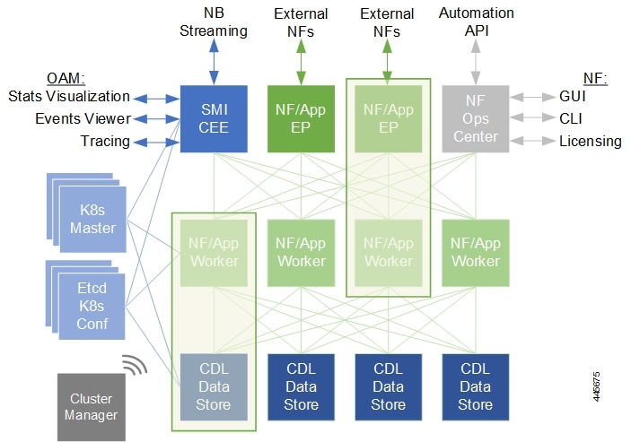
The Ultra Cloud Core Subscriber Microservices Infrastructure (SMI) provides a run time environment for deploying and managing Cisco's cloud-native network functions (cNFs), also referred to as applications.

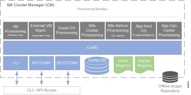
It is built around open source projects like Kubernetes (K8s), Docker, Helm, etcd, confd, and gRPC and provides a common set of services used by deployed cNFs including:

  • Protocol Load Balancing: These microservices provide the external NF interfaces (HTTP, Diameter, GTP, LDAP, etc.) and load balance requests to the application microservices. They normalize internal communications and allow application evolution independent of the interface evolution. Each protocol type is usually implemented as a separate microservice. gRPC is used for internal communication with the application microservices

  • Database Service: The database service provides a normalized gRPC interface to the application microservices. The database service can interface to different databases allowing the use of different back-end databases depending on the application requirements while maintaining the same interface.

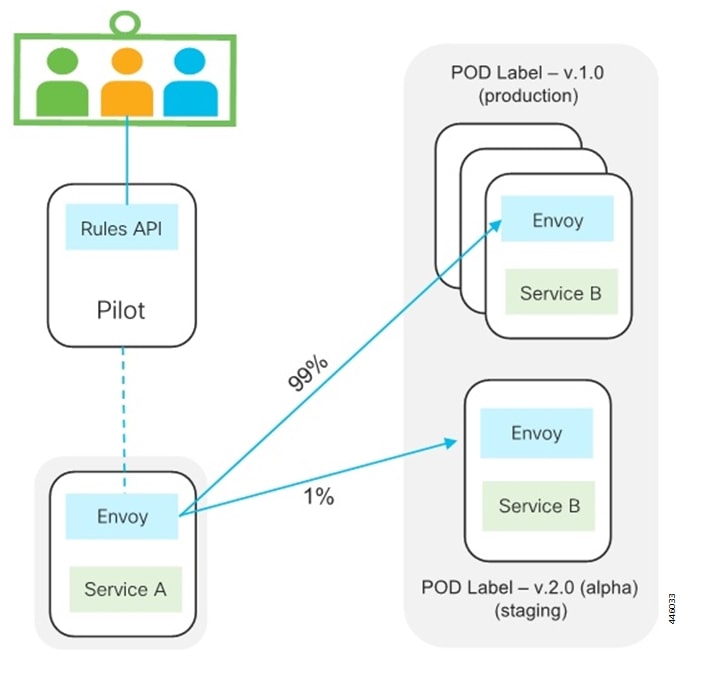
  • Cisco Service Mesh: This service provides rule-based control over load balancing decisions across different application containers. Through this service, SMI supports and automates operations such as canary upgrades, new service roll-outs, and in-service upgrades.

  • Telemetry Service: Telemetry functionality is provided through a common set of microservices which collect real-time statistics, alarms, logs from various deployed application components, and translates and streams them to external functions.

  • Dashboard Service: The dashboard service works with the telemetry service to provide operational overview data for application containers such as state, utilization, and key performance indicators (KPIs).

Cisco's cNFs are implemented as a set of microservices that make use of the common platform services offered by SMI. Refer to the NF's documentation for additional details.

SMI on Bare Metal - Overview

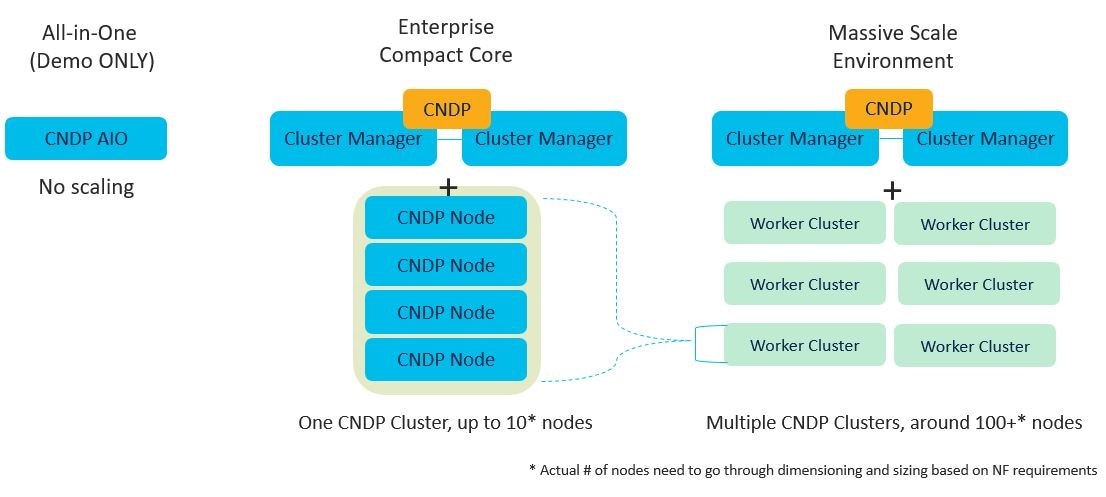
The SMI extends the deployment of Virtual Network Functions (VNF) and Cloud-Native Network Functions (CNFs) to bare metal servers (Cisco UCS-C servers) with the current release. Also, the SMI supports vertically integrated deployment on bare metal servers.

The following are some of the significant features deploying SMI on Bare Metal servers:

  • Elimination of VIM-related overhead on Bare Metal servers

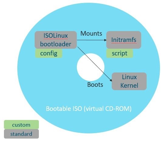
  • Zero touch deployment for both VNF and CNF based applications

  • Automated infrastructure upgrades

  • Exposed API for deployment, configuration, and management to enable automation.

  • Addresses edge deployment

    • Provides single compute user plane to run at remote sites

  • Scales out without any additional overhead

  • Ground up API (NETCONF, REST) driven design and architecture

    • All the interfaces are compliant with northbound NFVO (for instance, NSO).

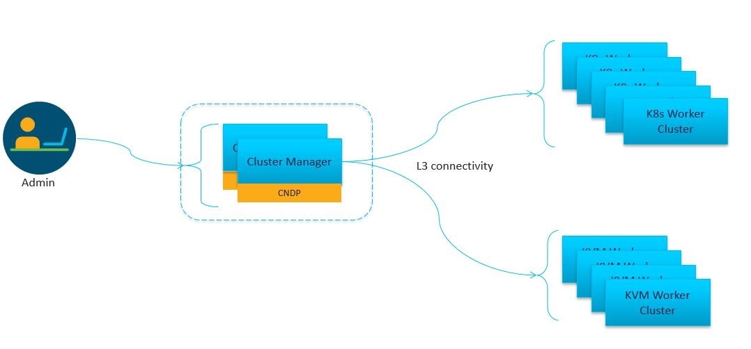
  • Simplification and remote management

  • Removes shared storage from the architecture

  • Single monitoring endpoint for both server and application health


Note


The SMI has the ability to run virtual machines for legacy applications (CUPS CP and UPF).

Subscriber Microservices Infrastructure Architecture

The Ultra Cloud Core Subscriber Microservices Infrastructure (SMI) is a layered stack of cloud technologies that enable the rapid deployment of, and seamless life cycle operations for microservices-based applications.

The SMI stack consists of the following:

  • SMI Cluster Manager — Creates the Kubernetes (K8s) cluster, creates the software repository, and provides ongoing Life Cycle Management (LCM) for the cluster including deployment, upgrades, and expansion.


    Note


    The SMI Cluster Manager can install all SMI based applications (including the SMI Cluster Manager) in a Day-0 manner. For Day-1 configurations, you can utilize the deployed application Ops Center.


    The SMI Cluster Manager supports the following platforms:

    • VMware — The Cluster Manager deploys the base images using the vSphere APIs.

    • Bare Metal — The Cluster Manager configures:

      • UCS-C server based hosts using Cisco Integrated Management Controller (CIMC) APIs.

    • Manual — The Cluster Manager allows other systems (NSO/ESC) to provision the base image and configure the K8s Cluster.

  • Kubernetes Management — Includes the K8s control plane and etcd functions which provide LCM for the cNF applications deployed in the cluster as well as provides cluster health monitoring and resources scheduling.

  • Common Execution Environment (CEE) — Provides common utilities and OAM functionalities for Cisco cNFs and applications, including licensing and entitlement functions, configuration management, telemetry and alarm visualization, logging management, and troubleshooting utilities. Additionally, it provides consistent interaction and experience for all customer touch points and integration points in relation to these tools and deployed applications.

  • Common Data Layer (CDL) — Provides a high performance, low latency, stateful data store, designed specifically for 5G and subscriber applications. This next generation data store offers HA in local or geo-redundant deployments.

  • Service Mesh — Provides sophisticated message routing between application containers, enabling managed interconnectivity, additional security, and the ability to deploy new code and new configurations in low risk manner.

  • NF/Application Worker nodes — The containers that comprise an NF application pod.

  • NF/Application Endpoints (EPs) – The NF's/application's interfaces to other entities on the network.

  • Application Programming Interfaces (APIs) — SMI provides various APIs for deployment, configuration, and management automation.

  • Ops Center — The SMI run time environment, as well as each Cisco cloud native application, includes an innovative management interface called Ops Center. This Netconf/Restconf interface, based on Yang schema, enables all configurations for SMI and Cisco cloud native applications, to be automated or managed directly through a CLI.

Figure 1 depicts how these components interconnect to comprise a microservice-based NF/application.

Figure 1. SMI Components

SMI Bare Metal - Architecture

The SMI enables the deployment of Cluster Manager on Bare Metal servers. The following are some of the salient features of SMI Bare Metal architecture:

  • Enables all the application containers to run on the bare metal servers with enough resource isolation

  • Provides a migration path for SMI on VM to SMI on bare metal

  • Automated bring up at the Data Center

  • Hardware agnostic architecture

The following figure depicts the high-level SMI Bare Metal Architecture:

Figure 2. SMI Bare Metal High-level Architecture

With the help of a Bootable ISO, the SMI Cluster Manager boots the Linux Kernel from the base image. This allows compatibility with most of the standard hardware platforms. A customized script downloads and writes the HD image using the Initial RAM File System. Also, the Bootable ISOs smaller size - 23 Mega Bytes (MB) - reduces latency.

The following figure depicts the operations of the Bootable ISO:

Figure 3. Bootable ISO

SMI Bare Metal Deployment Architecture

The SMI Bare Metal deployment architecture comprises of a two node Management Cluster. The two node cluster comprises of a SMI CEE (for monitoring) and SMI Cluster Manager running on it. Also, the two node cluster is responsible for:

  • installing and upgrading the BIOS, host OS, Kubernetes, KVM.

  • installing and upgrading Kubernetes based NFs.

  • adding the day-0 configuration to installed NFs.

  • installing StarOS NFs (UPF).

  • installing VPC-DI.

  • monitoring and alerting.

The SMI Cluster Manager provisions and manages the Life Cycle Management (LCM) of each worker node for both the K8s and Kernel based Virtual Machine (KVM) infrastructure.

The following figure depicts the high-level architecture of SMI Bare Metal Deployment architecture:

Figure 4. SMI Bare Metal Deployment Architecture

K8s Cluster Manager

SMI operational components and microservices are deployed on VMs. (Refer to SMI VM Quantities and Sizing for details.)

The SMI Cluster Manager (CM) is also deployed as a VM and is used to bootstrap the deployment of other components and applications.

The CM works with the Virtual Infrastructure Manager (VIM) to instantiate the required VMs. In VMware environments, the CM instantiates the virtual machines (VMs) required for the cluster. In OpenStack environments, the CM makes an API call to an orchestrator or Virtual Network Function Manager (VNFM) to instantiate VMs.

The VMs are deployed with a guest OS that is provided with SMI. Once instantiated, the CM provisions the OS, and deploys or provisions the SMI microservices (for example, K8s control plane, K8s etcd, and so on.).

Once all VMs and K8s components are built, the CM can deploy 5G application Ops Centers, which enable NETCONF/RESTCONF interfaces for application configuration and management. All of these actions are API driven and all can be automated and orchestrated.

Figure 5. SMI Cluster Manager Functionality

Scheduling rules such as affinity and anti-affinity help guide K8s for proper node placement, as well as adding node taint and tolerances. Because K8s uses a declarative method of deployment, operators simply need to update the desired number of services and K8s manages scheduling and maintains the correct number of services, even during failure scenarios.

K8s Resource Management

SMI leverages the native resource reservation controls in K8s.

K8s provides a framework to intelligently place pods on the correct server, VM, and/or node, and assign the appropriate system resources, including:

  • Service taints, tolerances, affinity, and anti-affinity rules

    • Provides rules for pod placement across available hardware

    • Prevents resource "hotspots" by separating pods with similar resource profiles

    • Provides high availability (HA) by ensuring secondary instances through pod separation

  • CPU reservation

    • Allows applications to specify CPUs/CPU requirements (similar to CPU pinning)

    • Prevents negative impacts from context switching, or noisy/grabby neighbors

  • Pod quality of service (QoS) definition (e.g. the quality and range of resources available to the Pods)

    • Guaranteed (resource requests = resource limits)

    • Burstable (resource requests > resource limits)

    • Best effort (no resource requests nor limits)

DSCP is implemented at the network level to manage the quality of service and ensure critical traffic is prioritized.

Common Execution Environment

SMI's Common Execution Environment (CEE) provides OAM capabilities for deployed NFs.

The CEE captures information (key metrics) from the NFs in a centralized way for engineers to debug and troubleshoot the overall solution.

There is only one CEE available per K8s cluster, which provides the common set of tools for all deployed NFs. CEE life cycle is independent of NF and it comes equipped with a dedicated Ops Center, which provides the user interface (CLI) and APIs for managing the monitoring tools.

Monitoring and Debugging

The SMI platform provides multiple layers of health checking:

  • Deployment health checks — These confirm that the infrastructure meets the application requirements.

    NOTE: Some deployment health checks (input/output operations per second (IOPS) validation and network throughput) may impact performance and should only be executed during the deployment phase.

  • Run time health checks — These checks are constantly running in the background to verify that logging and tracing are set to the lowest levels, and to check error rates and alarms.

  • Pod health checks — These confirm that the pod is alive and service availability. If the pod fails the health check, it is killed and re-scheduled onto another available node.

  • Performance checks — The checks provide such data as transactions per second (TPS), number of records (sessions), CPU and memory utilization, errors, etc.

Statistics are available for viewing through Grafana, as well as for streaming using Prometheus. They are also available in bulkstat format. The granularity of statistics can be as small as 1 second. Statistics are stored for up to 3 days using Thanos to compress and compact the data.

Logging utilizes journald and rsyslog to collect and distribute logs northbound to a fully featured logging platform. SMI also includes logging utilities to collect snapshots for troubleshooting and uploading to Cisco TAC support centers. Logging verbosity and detail levels are set via API, and can be set to Critical, Error, Warning, Informational, or Debug.

Application and platform events can be forwarded northbound using Prometheus plugins such as VES and/or SNMP.

Tracing

Cisco's cloud native based applications are designed to tag messages in a method compatible with OpenTracing project guidelines.

SMI provides tooling and centralized storage for continuous tracings of cNFs even as they may span across multiple nodes.

This tracing shows all "message spans" from platform ingress to platform egress as well as how long each unit of work takes.

Ops Center

Cisco's cNFs consist of Helm charts (applications and charts) and Docker files (images).

To simplify and establish consistent operations across the various charts and images that comprise each NF, each NF is designed with an Ops Center. Ops Centers provide a common, stable CLI/API for operators to deploy and manage the NF in a holistic way.

Figure 6. NF/Application Ops Center

SMI provides the following functionality in relation to NF Ops Centers:

  • Common NETCONF, RESTCONF, and CLI interfaces, which allows for integration network orchestrators such as Cisco's Network Services Orchestrator (NSO) without need for a custom network element driver (NED)

  • A YANG model for the application

  • Audit logging and configuration validation

  • Lightweight Directory Access Protocol (LDAP) interface directory information services — for example, Active Directory (AD) — to ensure all applications use a common set of user accounts

  • Cisco Smart Licensing integration

  • Callbacks into the application to execute operational commands

  • NETCONF Access Control (NACM) security model

Service Mesh

The Service Mesh enabled through SMI connects and manages messages between all pods and services in the cluster. Using this service mesh, traffic is steered within the cluster to finely control which NF components are part of the traffic flow.

Granular controls such as traffic percentage, or application-based traffic characteristics — for example, access point name (APN), subscription permanent identifier (SUPI), or other layer 7 attribute value pairs (AVPs) — are used to control traffic within the cluster. This control enables selective and precise upgrades, such as "canary upgrades". This limits risk and impact when deploying changes in-service and in production. It also affords the ability to selectively drain or decommission NFs.

Figure 7. SMI Service Mesh

Besides traffic management applications, the service mesh aids in tracking the flow of traffic between services and nodes, providing security to prevent unauthorized service access and isolating rogue services.

Common Data Layer

The Common Data Layer (CDL) component enabled through SMI provides the clean separation of stateful (also known as backing services) and stateless services (e.g. application services).

CDL provides services for efficiently managing stateful subscriber and identity information across all deployed Cisco NFs. The CDL is an in-memory database designed specifically for high performance carrier grade requirements and subscriber data. Separating stateful services in this way allows for the stateless application services to be autonomous, lightweight, upgradable, recoverable, and rapidly scalable.

Stateful services must address the availability, consistency, and portability of state. These typically require replication across one or more containers while maintaining state consistency.

As such, CDL redundancy is achieved by local and remote replication of session data. In addition, a background process scans the data store for inconsistencies, stale data, and corruption, and corrects them both locally and remotely.

SMI VM Quantities and Sizing

Table 1 and Table 2 provide SMI VM quantity and sizing recommendations.

NOTE: Individual NFs are deployed as K8s workers through SMI. They each have their own VM recommendations. Refer to the NF documentation for details.

Table 1. SMI VM Function and Quantities
VM Purpose Redundancy # VMs
SMI Cluster Manager NA 1
K8s Control Plane 3 3
K8s Etcd 3 3
OAM 3 3
Table 2. SMI VM Sizing Recommendations
VM Function vCPUs NUMA per VM (Single/Double) CPU Pinned RAM (GB) Boot Volume Size (GB) Data Volume Size (GB)
SMI Cluster Manager 2 1 Yes 16 40 100
K8s Control Plane 2 1 Yes 16 100 20
K8s Etcd (CDL) 2 1 Yes 16 100 20
OAM 12 1 Yes 112 100 200

SMI Bare Metal Hardware Requirements

The following table lists the minimum Bare Metal requirements for deploying SMI Cluster Manager.

Table 3. SMI Bare Metal Hardware Requirements (UCS-C Series)
Item Requirements

Server

Cisco UCS C220 M5/M6/M7

Networking

  • Cisco Catalyst 3850 Switches

  • Cisco Nexus 9000 Series Switches

bbg

SSD

Note


For Disk drives, you must use SSDs to improve the read/write access speed.


Note


The Bare Metal requirements listed in the table for deploying SMI Cluster Manager are for reference only. For specific requirements, contact your Cisco account representative.


Redundancy

SMI enables redundancy at multiple levels:

  • Network — This is provided by the infrastructure and hardware with dual networking paths, dual NICs, and interface bonding. It is also provided by the SMI platform through the use of virtual IP addesses (VIPs), load balancers (LBs), and through the use of Cisco's Service Mesh.

  • K8s cluster — The K8s cluster leverages a multiple control plane design.

    In order to avoid potential conflicts if two components modify the same objects, K8s implements a leader/follower pattern for the controller manager and the scheduler. Each group elects one leader, then the other group members assume follower roles. At any point in time, only the leader is active, and the followers are passive.

    K8s configuration (etcd) also uses a consensus-based leader/follower election process. Storage includes Storage Area Network/Network Area Storage (SAN/NAS) for persistence during server of VM failure. On leader failure, a new election takes place to determine a new leader. When the old leader recovers, it comes back as follower. Nothing happens on follower failure.

  • OAM services — OAM services are deployed in large VMs on two or more nodes. Storage includes SAN/NAS for persistence during VM failure. Services are designed to reserve 50%+ capacity per server in order to allow K8s to reschedule services to next available OAM nodes without impact during a failure.

  • NF applications — Cisco's stateless applications support N+1 redundancy and rely on K8s to monitor and reschedule when necessary. Application components are distributed across servers for HA purposes.

Security

SMI provides several secure methods for accessing, managing, and configuring the system, all based on APIs, including the Ops Center CLI, and NETCONF/RESTCONF interfaces.

Monitoring interfaces such as Grafana also integrate security and authentication using LDAP Systems Security Services Daemon (SSSD) and Secure Architecture for the Networked Enterprise (SANE).

Access and any configuration changes using the provided CLI and/or API are securely logged.