SMI Cluster Manager - Deployment

Deployment Workflow

The SMI Cluster Manager deployment workflow consists of:

  • Deploying the Inception Server

  • Deploying the Cluster Manager

  • Deploying the Kubernetes Cluster

  • Deploying Cloud Network Functions (CNFs)

  • Deploying VNF VMs (SMI Bare Metal Deployment)

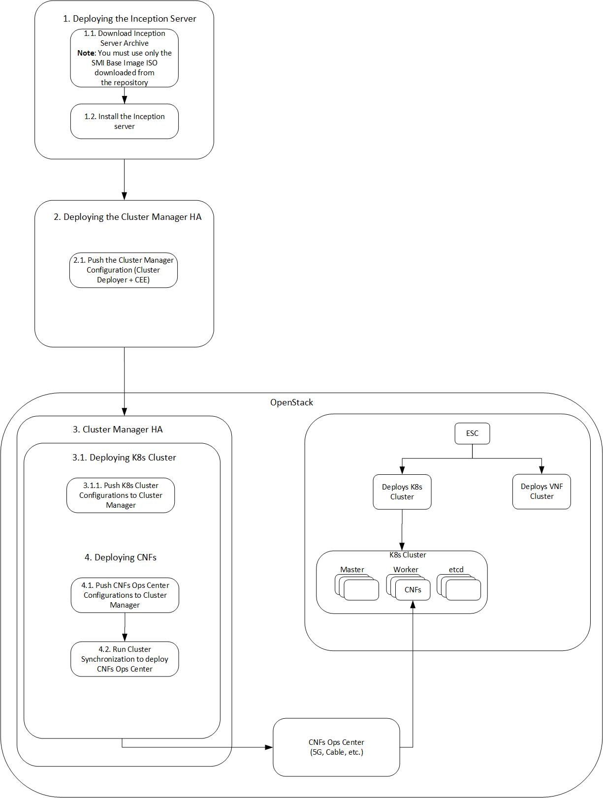
The following figures depict the deployment work flow of the Cluster Manager:

Figure 1. Deployment Workflow - Bare Metal
Figure 2. Deployment Workflow - VMware
Figure 3. Deployment Workflow - OpenStack

The subsequent sections describe these deployment workflows in detail.

Introduction to Deploying SMI Cluster Manager

This chapter provides information about deploying the SMI Cluster Manager on a High Availability (HA) and All-In-One (AIO) mode using the Inception Server. The Inception Server is a version of Cluster Manager running only on Docker and Docker Compose. A Base OS is required to bring up the Inception Server on a host machine. The Base OS is provided through an ISO image (Virtual CD-ROM) called the SMI Base Image ISO. You can bring up the Inception Server using the SMI Base Image ISO.

The subsequent sections provide more information about deploying the SMI Base Image ISO on the host machine, deploying the Inception Server and SMI Cluster Manager.


Note


The SMI supports only the UTC time zone by default. Use this time zone for all your deployment and installation activities related to the SMI.


Important


The /home directory is reserved for the SMI Cluster Deployer. Do not use this directory for storing data. If you must store data, use the /data directory instead.


SMI Base Image ISO

The SMI uses a generic installable SMI Base Image ISO (Virtual CD-ROM) for installing the SMI Base image. Currently, the SMI uses a hardened Base OS as the Base image. This ISO image replaces the existing VMDK and QCOW2 artifacts used in the previous SMI releases. The ISO boots and writes the storage device images onto a Virtual Machine (VM) or Bare Metal storage device. Using the SMI Base Image ISO, you can install an OS for the Inception server or install the Base OS for manual deployments (For example, OpenStack).

This ISO image boots the first storage device - with a minimum of 100 GB in size for production - and writes the storage device image to the disk. Additionally, you can use a cloud-init ISO along with the SMI Base Image ISO to configure the cloud-init data, which is required for building a cloud-init ISO. When no cloud-init ISO is found, the SMI uses the default configuration.


Note


  • For providing ISO compatibility on platforms, which do not allow the mounting of ISO files and also for simplifying the deployment on OpenStack, the SMI Base Image ISO can overwrite its own disk (when the disk is greater than 100 GB in size).

  • For accessing and downloading the cloud-init ISO from the repository, contact your Cisco Account representative.

  • The Linux source operating system is upgraded to Ubuntu 22.04.


Note


By default, the user password expiry is set to PASS_MAX_DAYS (/etc/login.defs). Password expiration days must be extended to avoid access lock. For remote hosts, user password days can be configured by using the following CLI configuration:

deployment.node-defaults initial-boot default-user-password-expiration-days [0-9999]


Note


For base images with restricted umask in CM HA nodes, run the sudo command to view the correct DRBD-overview output.


Base Image Patch

The Base Image Patch feature enables the application of patches to the base image in a non-disruptive manner, avoiding the need for a full A/B upgrade. This is useful to apply security patches and minor updates to the kernel and other software components.

Benefits of Base Image Patch

  • Non-Disruptive Updates: Allows for patching without the need for a full A/B upgrade, reducing downtime and the risk of upgrade failures.

  • Security: Facilitates the application of security patches to the kernel and other critical components.

  • Flexibility: Supports updates to third-party software, libraries, and kernel modules.

Restrictions of Base Image Patch

Major base image changes, such as upgrading versions of the operating system (for example, Ubuntu 20.04 to 22.04), still requires an A/B upgrade.

Patch File Format

The patch is available as a downloadable .tgz file. The cluster manager must have access to the patch file.

Configure Base Image Patch

You can apply the patch from the cluster manager using one of the following methods:

  • During full cluster synchronization

  • Directly through synchronization phase

Before you begin

Ensure that the cluster manager has access to the patch file.

The patch can be downloaded and configured using these CLI commands:

  • Use show running-config software patch at cluster-level

  • Use show running-config clusters cluster_name node-defaults os patch at node-level

Procedure

Step 1

Apply the patch during full cluster synchronization using the actions sync run disable-partition-upgrade CLI to disable partition upgrade (A/B upgrade).

Example:
[host] SMI Cluster Deployer# config 
[host] SMI Cluster Deployer # clusters cluster_name actions sync run disable-partition-upgrade { true | false } 
[host] SMI Cluster Deployer# exit 
[test-aio-master] SMI Cluster Deployer# clusters test-smi-vm actions sync run disable-partition-upgrade true 
This will run sync.  Are you sure? [no,yes]

Step 2

Apply the patch directly through sync-phase using the actions sync run sync-phase patch CLI.

Example:
[host] SMI Cluster Deployer# config 
[host] SMI Cluster Deployer # clusters cluster_name actions sync run sync-phase patch 
[host] SMI Cluster Deployer# exit 
[test-aio-master] SMI Cluster Deployer# clusters test-smi-vm actions sync run sync-phase patch 
This will run sync.  Are you sure? [no,yes] yes
message accepted
warning "k8s node-type master" for node master is deprecated. Use "k8s node-type control-plane" instead

Step 3

Run these commands to verify the status of patch installation:

  1. actions patch pre-check to identify any issues before applying a patch

  2. actions patch status to view the current patch status

Example:
[host] SMI Cluster Deployer# config 
[host] SMI Cluster Deployer # clusters cluster_name actions patch status 
[host] SMI Cluster Deployer # clusters cluster_name actions patch pre-check 
[host] SMI Cluster Deployer# exit 
=========== First patch
[test-sim-vm] SMI Cluster Deployer# clusters test-cm actions patch status             
status standby: 
  - PATCH_VERSION: 20.04.0-20240709-20240925
active: 
  - PATCH_VERSION: 20.04.0-20240709-20240925
  
[test-sim-vm] SMI Cluster Deployer# clusters test-cm actions patch pre-check 
status standby: 
  - pre_check_result: Already applied
active: 
  - pre_check_result: Already applied

=========== Second patch
[test-sim-vm] SMI Cluster Deployer# clusters test-cm actions patch pre-check          
status standby: 
  - pre_check_result: Already applied
active: 
  - pre_check_result: Already applied

[test-sim-vm] SMI Cluster Deployer# 
[test-sim-vm] SMI Cluster Deployer# 
[test-sim-vm] SMI Cluster Deployer# clusters test-cm actions patch status   
status standby: 
  - PATCH_VERSION: 20.04.0-20240709-20241021
active: 
  - PATCH_VERSION: 20.04.0-20240709-20241021

Inception Server Deployment Sequence

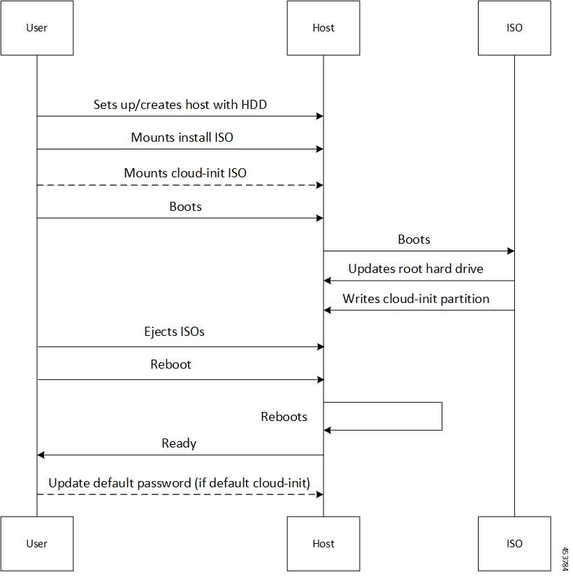
The following call flow depicts the installation of the Inception Server using SMI Base Image ISO:

Figure 4. Inception Server Deployment Sequence
Table 1. Inception Server Deployment Sequence

Steps

Description

1

User creates a new VM or host or uses an existing host.

2

User mounts the ISO.

  • (Optional) Mount cloud-init ISO.

3

After the machine boots, the ISO performs the following:

  • The first hard drive that meets the minimum requirements is selected and formatted. The base image is written on the formatted hard drive.

  • If cloud-init ISO is found, the cloud-init data from the ISO is used.

  • If there is no cloud-init ISO, the default cloud-init data is used.

4

The user ejects the ISO and reboots the host machine.

Installing the Base Image on Bare Metal

The SMI Cluster Manager uses a Base OS as its base image. You can install the base image through an ISO file. Optionally, you can provide the network and user configuration parameters through a cloud-init ISO file.


Note


For deploying the Inception Server, you must use only the SMI Base Image ISO downloaded from the repository. Contact your Cisco Account representative to download the SMI Base Image ISO from the repository.

The SMI Cluster Manager installs the Sysstat Package Manager system utility on all hosts during deployment to provide real-time debugging capabilities.

Prerequisites

The following are the prerequisites for installing the SMI base image:

  • Download the SMI base image ISO file from the repository.

  • (Optional) Create a NoCloud ISO to provide cloud-init data to the machine.

  • Configure the following when there is no cloud-init NoCloud ISO:

    • DHCP for networking.

    • Default user name. For example, cloud-user.

    • Default password. For example, Cisco_123 (You must change the password immediately after the setup).

SMI Base Image Installation on Bare Metal

To install the SMI base image on Bare Metal:

  1. Upload the SMI base image ISO on a HTTP/HTTPS or Network File System (NFS) server.

  2. Ensure that the HTTP/HTTPS server is reachable by the bare metal server manager, for example, Cisco Integrated Management Controller (CIMC) server for the UCS server .


    Note


    The latency between the bare metal server manager and HTTP/HTTPS server must be lesser to avoid any delays in processing the request.


  3. Log in to the bare metal server manager.

  4. Ensure that the Virtual Drive is setup as a single disk.

  5. Mount the ISO as Virtual Media on host.

  6. Select CDROM in the boot order followed by HDD.

    • Ensure that the boot order is not setup through any other boot method.

  7. Reboot the host and follow the instructions on the KVM console.

Installing the Base Image on VMware

The SMI Cluster Manager uses a Base OS as its base image. You can install the base image through an ISO file. Optionally, you can provide the network and user configuration parameters through a cloud-init ISO file.


Note


For deploying the Inception Server, you must use only the SMI Base Image ISO downloaded from the repository. Contact your Cisco Account representative to download the SMI Base Image ISO from the repository.

Prerequisites

With the current release, the SMI supports VMware vCenter version 7.0.


Note


The previous vCenter versions (6.5 and 6.7) are deprecated in the current release. These versions will not be supported in the future SMI releases. For more details about end of life support for these versions, contact your Cisco account representative.


The following are the prerequisites for installing the SMI base image:

  • VMware vSphere Hypervisor (ESXi) 6.5 and later versions. The VMware vSphere Hypervisor (ESXi) 6.5 and 6.7 have been fully tested and meets performance benchmarks.

  • Download the SMI base image ISO file from the repository.

  • (Optional) Create a NoCloud ISO to provide cloud-init data to the machine.

  • Configure the following when there is no cloud-init NoCloud ISO:

    • DHCP for networking.

    • Default user name. For example, cloud-user.

    • Default password. For example, Cisco_123 (You must change the password immediately after the setup).

Minimum Hardware Requirements - VMware

The following are the minimum hardware requirements for deploying the SMI Base Image ISO on VMware:

  • CPU: 8 vCPUs

  • Memory: 24 GB

  • Storage: 200 GB

  • NIC interfaces: The number NIC interfaces required is based on the K8s network and VMware host network reachability.

SMI Base Image Installation on VMware

To install the SMI base image on VMware:

  1. Upload the SMI base image ISO into the datastore manually.


    Note


    Create a new folder to store these images separately.


  2. (Optional) Upload the NoCloud cloud-init ISO manually, if you have created it.

  3. Create a VM with access to the datastore, which has the SMI base image and NoCloud ‘cloud-init’ ISOs.

  4. Power on the VM

  5. Connect to the console

Installing the Base Image on OpenStack

The SMI Cluster Manager uses a Base OS as its base image. You can install the base image through an ISO file. Optionally, you can provide the network and user configuration parameters through a cloud-init ISO file.


Note


For deploying the Inception Server, you must use only the SMI Base Image ISO downloaded from the repository. Contact your Cisco Account representative to download the SMI Base Image ISO from the repository.

Prerequisites

The following are the prerequisites for installing the SMI base image (in all the platforms):

  • Download the SMI base image ISO file from the repository.

  • (Optional) Create a NoCloud ISO to provide cloud-init data to the machine.

  • Configure the following when there is no cloud-init NoCloud ISO:

    • DHCP for networking.

    • Default user name. For example, cloud-user.

    • Default password. For example, Cisco_123 (You must change the password immediately after the setup).

SMI Base Image Installation on OpenStack

To install the Base Image on OpenStack:

  1. Log in to Horizon.

  2. Navigate to Create Image page and fill in the following image details:

    • Image Name - Enter a name for the image.

    • Image Description (Optional) - Enter a brief description of the image.

    • Image Source - Select File as the Image Source.

    • File - Browse for the ISO image from your system and add it.

    • Format - Select the Image Format as Raw.

    • Minimum Disk (GB) - Specify the minimum disk size as 100GB.

  3. Click Create Image.


    Note


    It might take several minutes for the image to save completely.
  4. Navigate to the Launch Instance page.

  5. Click Details tab and fill in the following instance details:

    • Instance Name - Enter a name for the instance.

    • Count - Specify the count as 1.

  6. Click Source tab and fill in the following details:

    • Select Boot Source - Select the Base Image from the drop-down list.

    • Volume Size (GB) - Increase the volume size if required.

  7. Click Flavor tab and select a flavor which meets the minimum requirements for the VM from the grid..


    Note


    You can create a new flavor if required.
  8. Click Networks tab and select the appropriate networks for the VM based on your environment.

  9. Click Key Pair tab to create or import key pairs.

    • Click Create Key Pair to generate a new key pair.

    • Click Import Key Pair to import a key pair.

  10. Click Configuration tab to add user configuration.

    • To configure the host name and output the cloud-init details to a log file, use the following configuration:

      #cloud-config
      output:
         all: '| tee -a /var/log/cloud-init-output.log | tee /dev/ttyS0'
      hostname: "test-cluster-control-1"

      Note


      If users and private keys are added to cloud-init, it overrides the OpenStack Key Pairs.
    • By default, log in access to the console is denied. To enable password log in at the console, use the following configuration.

      #cloud-config
      chpasswd:
         list: |
           ubuntu:my_new_password
         expire: false
  11. Click Launch Instance.


    Note


    To monitor the boot progress, navigate to the Instance Console. Also, you can interact with the console and view the boot messages through Console and Log tab respectively.

Host OS User Password Policy

You can configure a password policy for different user accounts on the host OS. Use the following command to set a password policy:

$ cat /etc/security/pwquality.conf

Based on the policy, a password must meet the following criteria:

  • Minimum 14 characters in length.

  • Contain at least one lowercase character.

  • Contain at least one uppercase character.

  • Contain at least one numeric character.

  • Contain at least one special character.

  • Password must not be too simplistic or based on dictionary word.

  • Do not re-use passwords.

    Use the following commands to configure the number of passwords to keep in history:

    $ cat /etc/pam.d/common-password
    password required  pam_pwhistory.so use_authtok remember=5
  • Minimum number of days that are allowed between password changes is seven.

Introduction to Inception Server

The Inception Server is a replacement to the K3s based VM Cluster Manager. You can use the Inception Server to deploy the SMI Cluster Manager in HA or AIO mode. The Inception Server runs on a Base OS (SMI Base Image) with Docker and Docker Compose.

Installing the Inception Server on smi-install-disk.iso

This section describes the procedures involved in deploying the Inception Server on the host machine, which has the Base OS installed.


Note


The procedure to deploy the Inception Server on a host machine with the Base OS installed is the same irrespective of the host machine's environment (Bare Metal, VMware or OpenStack).


Prerequisites

The following are the prerequisites for deploying the Inception Server:

  • Download the SMI Cluster Deployer tarball from the repository. The tarball includes the following software packages:

    • Docker

    • Docker-compose

    • Registry


    Note


    For downloading the SMI Cluster Deployer tarball from the repository, contact your Cisco Account representative.


Configuring User and Network Parameters

This section describes the procedures involved in configuring the user and network parameters when Cloud-init ISO not available.

To configure SSH access:

  1. Access the console.

  2. Login with the default cloud-init credentials.


    Note


    You must change the password immediately after logging in.


To configure the network and static IP addressing:

  1. Login to the console.

  2. Update the network configuration in /etc/netplan/50-cloud-init.yaml file.

    The following is a sample network configuration:

    network:
        ethernets:
            ens192:
                addresses:
                - "ipv4addrees/subnet"
                dhcp4: false
                gateway4: gateway_address
                nameservers:
                    addresses:
                    - ipvtaddress
                    - ipv4address
                    - ipv4address
    version: 2
     

    Important


    When upgrading to Ubuntu 22.04, use routes: gateway_address instead of gateway4: gateway_address in your network configuration.


  3. Run the following command to apply the configuration:
    sudo netplan apply 
  4. Exit the console.

  5. Access the machine through SSH.

DNS Server Configuration

This section outlines the steps necessary to implement DNS server configuration on Kubernetes (k8s) nodes.

To accomplish this task, you should perform these steps:

  1. Configure the DNS nameserver

    • Using SMI Cluster Manager or

    • Manual method

  2. Update the CoreDNS Configuration for Nameserver Selection

Starting with SMI release 2025.01.1, the system sets the nameserver address and search parameters under the netplan grouping as "ordered-by-user." This means that the SMI cluster manager configures these parameters in the exact order specified by the user in the deployment object. Previously, the system set these parameters as "ordered-by-system," configuring them in lexicographical order. Releases from 2025.01.1 onward preserve the specified order, while earlier versions follow the default lexicographical order.

Upgrade Considerations

During the upgrade to the 2025.01.1 SMI builds, the system will retain the configured order of any existing nameserver addresses and search parameters. The upgrade process will not alter the order of these configurations.


Important


When upgrading to Ubuntu 22.04, set only a single gateway for each IP address family in your netplan configuration to avoid any ambiguity. If you need multiple default routes, define them using routing-policy.


Configure the DNS Nameserver Using SMI Cluster Manager

Follow these steps to configure the nameserver address and search parameters in the SMI Cluster Manager:

Procedure

Step 1

Enter the config mode and deploy the cluster in the SMI deployment.

smi deployment $DEP_NAME clusters cluster $CLUSTER_NAME

Example:
admin@ncs(config)# smi deployment test clusters cluster c1

Step 2

Configure the netplan additions on cluster.

Example:
admin@ncs(config-cluster-c1)# netplan-additions vlan 12

Step 3

Configure the nameserver address in netplan in the desired order.

Example:
admin@ncs(config-vlan-12)# nameservers addresses [ 209.165.200.225 209.165.200.254 209.165.201.1 ]

Step 4

Configure the nameserver search in netplan in the desired order.

Example:
admin@ncs(config-vlan-12)# nameservers search [ foo.com bar.com baz.com ]

Step 5

Save and commit the configuration.


Test and Apply Netplan Configuration

Once the DNS IP addresses and other parameters are configured, test the configurations to verify if they work correctly.

Procedure

Step 1

Verify the nameserver IP addresses on the nodes by checking /etc/resolv.conf using the following command:

cat /etc/resolv.conf | grep "nameserver\|search"

Step 2

Run the cluster synchronization command for the configuration to take effect:

clusters cluster-c1 actions sync run sync-phase netplan debug true

Step 3

Confirm the action when prompted.


Configure the DNS Nameserver Manually

If you are manually configuring the DNS server settings, follow these steps:

Procedure

Step 1

Edit the /etc/systemd/resolved.conf file on all master nodes to configure the DNS IP addresses.

Step 2

Restart the systemd-resolved service:

sudo systemctl restart systemd-resolved

Step 3

(Optional) Ensure the DNS server is configured as the first entry in /etc/resolv.conf:

cat /etc/resolv.conf


Update CoreDNS Configuration for Nameserver Selection

Follow these steps to update the CoreDNS parameters in the CoreDNS ConfigMap:

Procedure

Step 1

On the master node, edit the coreDNS ConfigMap using the following command:

kubectl -n kube-system edit configmaps coredns -o yaml

Step 2

Add the policy as “sequential” under the “forward” section:

forward . /etc/resolv.conf {
    max_concurrent 1000
    policy sequential
}

Step 3

Restart the coreDNS deployment:

kubectl -n kube-system rollout restart deployment coredns


Deploying the Inception Server

To deploy the Inception Server, use the following configuration:

  1. Login to the host, which has the Base OS installed.

  2. Create a temporary folder to store the downloaded offline SMI Cluster Manager products tarball.

    mkdir /data/offline-cm 
    Example:
    user1@testaio:~$ mkdir /data/offline-cm
    user1@testaio:~$ cd /data/offline-cm/
    user1@testaio:/data/offline-cm$
  3. Fetch the desired tarball to the newly created temporary folder. You can fetch the tarball either from the artifactory or copy it securely through the scp command.

    /data/offline-cm$ wget --user [user] --ask-password [password] <repository_url>
     

    In the following example, the tarball is fetched from the artifactory using basic authentication:

    Example:

    user1-cloud@testaio-cmts-control-plane:/data/offline-cm$ 
      wget --user [user1] --password [user@123] <http://<repo_url>/cluster-deployer-2020-04-12.tar>
    
  4. Untar the offline Cluster Manager tarball.

    /data/offline-cm$ tar xvf <filename> 

    Example:

    user1@testaio-cmts-control-plane:/data/offline-cm$ tar xvf cluster-deployer-2020-04-12.tar
    
  5. Navigate to the deployer-inception folder which has the required charts and docker files.

    /data/offline-cm/data$ cd deployer-inception/ 
    Example:
    user1@testaio-cmts-control-plane:/data/offline-cm/data$ cd deployer-inception/
  6. Run the following command to deploy the Inception Server.

    sudo ./deploy --external-ip <external_ipaddress> --first-boot-password "<first_boot_password>" 

    Note


    • During a fresh installation of the Inception Server, you can load the first boot configuration automatically through the deploy command. The first boot configuration is a YAML file which contains all the original passwords. Loading the first boot configuration is a one-time operation.
      ./deploy --external-ip <external_ipaddress> --first-boot-password '<first_boot_password>' --first-boot-config /var/tmp/cluster-config.conf 
      Example:
      user1@testaio-cmts-control-plane:/data/offline-cm/data/deployer-inception$./deploy --external-ip <ipv4address> --first-boot-password '<first_boot_password>' --first-boot-config /var/tmp/cluster-config.conf
      
    • For security reasons, ensure that the first boot configuration YAML file is not stored anywhere in the system after you bring up the Inception server.


    Example:
    user1@testaio-cmts-control-plane:/data/offline-cm/data/deployer-inception$ ./deploy --external-ip <ipv4address> --first-boot-password '<first_boot_password>'

    The following examples displays the connection details on the console when the Inception Server setup completes:

    Connection Information
    ----------------------
    SSH (cli): ssh admin@127.0.0.1 -p 2022
    Files: https://files-offline.smi-deployer.10.85.109.252.nip.io
    API: https://restconf.smi-deployer.10.85.109.252.nip.io
  7. Verify the list of the containers after the Inception Server is installed.

    sudo docker ps 

    Example:

    user@u20-inception-252:~/data/deployer-inception$ docker ps
    CONTAINER ID  IMAGE                                 COMMAND                 CREATED     STATUS     PORTS                                     NAMES
    de5dac28c575  //cluster_synchronizer:1.2.0-f000c25  "/usr/bin/npm run st…"  4 days ago  Up 4 days                                            smi-cluster-deployer_cluster_sync_1
    f043cd13abaa  //nginx:1.2.0-ff992e0                 "/usr/local/bin/run-…"  4 days ago  Up 4 days                                            smi-cluster-deployer_ingress_1
    0dee8eed93ef  //metrics:1.2.0-9ae401f               "python3 /usr/local/…"  4 days ago  Up 4 days                                            smi-cluster-deployer_metrics_1
    eb1e13cf34e7  //confd_notifications:1.2.0-fe37e9e   "/usr/local/bin/run-…"  4 days ago  Up 4 days                                            smi-cluster-deployer_confd_notifications_1
    6a2a73827f38  //config_mgmt:1.2.0-61bfe40           "/usr/local/bin/run-…"  4 days ago  Up 4 days                                            smi-cluster-deployer_config_mgmt_1
    079905616eba  //cluster_offline_files:1.2.0-f42a431 "/usr/bin/supervisord"  4 days ago  Up 4 days                                            smi-cluster-deployer_cluster-offline-files_1
    6453ec01a39f  //confd:1.2.0-cc7013e                 "/usr/local/bin/uid_…"  4 days ago  Up 4 days  0.0.0.0:443->443/tcp, :::443->443/tcp     smi-cluster-deployer_confd_1
    c3b45608d664  registry:2                                                                           0.0.0.0:5000->5000/tcp, :::5000->5000/tcp

    Note


    For upgrading the Inception server, see Upgrading the Inception Server section.


NOTES:

  • external_ipaddress —Specify the interface IP address that points to your Converged Interconnect Network (CIN) setup. It hosts the ISO and offline tars to be downloaded to the remote hosts.

  • first_boot_password —Specify the first boot password. The first boot password is a user-defined value.

Installing the Inception Server using Ubuntu 22.04 LTS

Ubuntu 22.04 LTS can be used as a replacement for the smi-install-disk.iso image to simplify the maintenance of the host server running the Inception Deployer.

Users are allowed to install their own Ubuntu servers to manage security updates on their own, and install new releases of the cluster-deployer as required.

Prerequisites

The following are the prerequisites for installing the Ubuntu server:

  • ubuntu-22.04.5-live-server-amd64.iso (downloaded from https://releases.ubuntu.com)

  • VMware vSphere

  • Basic VM sizing recommendations:

    • 8 vCPU

    • 32 GB memory

    • 200 GB disk

  • Separate /tmp partition in Exec mode

  • Executable permission for /tmp directory in Docker Compose

Installing Ubuntu

To install Ubuntu 22.04, use the following procedure:

  1. Create a VM using ubuntu-22.04.5-live-server-amd64.iso.

  2. Create an ext4 disk partition named /tmp with 20 GB size. The smi-base-iso creates this partition automatically.

    The remaining disk can be partitioned as required.

  3. Add the networking and user settings as required.

  4. After the installation is completed, perform OS updates (sudo apt upgrade).

To deploy the inception server, it is recommended to freshly install the Inception Deployer on a newly installed VM. Refer to the procedure in the Deploying the Inception Server section.

Installing Cluster Deployer on RHEL

You can install the inception deployer on Red Hat Enterprise Linux (RHEL) to enable Linux agnostic deployment. The supported version of RHEL is 8.9.

Prerequisites

The following are the prerequisites for installing the cluster deployer on RHEL:

  • Install RHEL version 8.9 with Python 3, and the latest stable version of containerd, Docker, and Docker Compose

  • Ensure Python 3 is running by issuing the following command:

    cloud-user@rhel89 inception]$ python --version 
  • Separate /tmp partition in Exec mode

  • Executable permission for /tmp directory in Docker Compose

Installing Inception Server in RHEL

To install the inception server using RHEL, use the following procedure:

  1. Bring up the RHEL 8 server.

  2. Install Python 3 and Docker in RHEL 8 server.

    • Check the existence of docker-compose and not the version.

    • If Docker is not installed and not initiated, stop the inception server installation.

  3. Download the cluster deployer in the RHEL 8 server and install the inception server.

    [cloud-user@localhost deployer-inception]$ cat /etc/os-release
    NAME="Red Hat Enterprise Linux"
    VERSION="8.1 (Ootpa)"
    ID="rhel"
    ID_LIKE="fedora"
    VERSION_ID="8.1"
    PLATFORM_ID="platform:el8"
    PRETTY_NAME="Red Hat Enterprise Linux 8.1 (Ootpa)"
    ANSI_COLOR="0;31"
    CPE_NAME="cpe:/o:redhat:enterprise_linux:8.1:GA"
    HOME_URL="https://www.redhat.com/"
    BUG_REPORT_URL="https://bugzilla.redhat.com/"
    
    REDHAT_BUGZILLA_PRODUCT="Red Hat Enterprise Linux 8"
    REDHAT_BUGZILLA_PRODUCT_VERSION=8.1
    REDHAT_SUPPORT_PRODUCT="Red Hat Enterprise Linux"
    REDHAT_SUPPORT_PRODUCT_VERSION="8.1"
    
    [localhost.localdomain] SMI Cluster Deployer#
    [localhost.localdomain] SMI Cluster Deployer# show version
    app-version 2024.01.1.i12
    chart-version 1.2.0-2024-01-1-2027-240120184610-b3cb38b
    [localhost.localdomain] SMI Cluster Deployer# exit
    Connection to 10.0.0.1 closed.

Upgrading the Inception Server

To upgrade the Inception Server, use the following configuration:

  1. Login to the host, which has the Base OS installed.

  2. Navigate to the /data/offline-cm folder.


    Note


    The offline-cm folder was created while deploying the Inception Server. For more details, see Deploying the Inception Server section.


  3. Remove the data folder.

    rm -rf data 
  4. Fetch the desired tarball to the offline-cm folder. You can fetch the tarball either from the artifactory or copy it securely through the scp command.

    /data/offline-cm$ wget --user [user] --ask-password [password] <repository_url>
     

    In the following example, the tarball is fetched from the artifactory using basic authentication:

    Example:

    user1-cloud@testaio-cmts-control-plane:/data/offline-cm$ 
      wget --user [test_user1] --password [user@123] <http://<repo_url>/cluster-deployer-2020-04-12.tar>
    
  5. Untar the offline Cluster Manager tarball.

    /data/offline-cm$ tar xvf <filename> 

    Example:

    user1@testaio-cmts-control-plane:/data/offline-cm$ tar xvf cluster-deployer-2020-04-12.tar
    
  6. Navigate to the deployer-inception folder which has the required charts and docker files.

    /data/offline-cm/data$ cd deployer-inception/ 
    Example:
    user1@testaio-cmts-control-plane:/data/offline-cm/data$ cd deployer-inception/
  7. Run the following command to deploy the Inception Server.

    ./deploy --external-ip <external_ipaddress> --first-boot-password "<first_boot_password>" 
    Example:
    user1@testaio-cmts-control-plane:/data/offline-cm/data/deployer-inception$ ./deploy --external-ip <ipv4address> --first-boot-password "<first_boot_password>"
    The following connection details is displayed on the console when the Inception Server setup completes:
    Connection Information
    ----------------------
    SSH (cli): ssh admin@localhost -p <port_number>
    
    Files: https://files-offline.<ipv4address>.<domain_name>
    UI: https://deployer-ui.<ipv4address>.<domain_name>
    API: https://restconf.<ipv4address>.<domain_name>
  8. Verify the list of the containers after the Inception Server is installed.

    sudo docker ps 

    Example:

    user@u20-inception-252:~/data/deployer-inception$ docker ps
    CONTAINER ID  IMAGE                                 COMMAND                 CREATED     STATUS     PORTS                                     NAMES
    de5dac28c575  //cluster_synchronizer:1.2.0-f000c25  "/usr/bin/npm run st…"  4 days ago  Up 4 days                                            smi-cluster-deployer_cluster_sync_1
    f043cd13abaa  //nginx:1.2.0-ff992e0                 "/usr/local/bin/run-…"  4 days ago  Up 4 days                                            smi-cluster-deployer_ingress_1
    0dee8eed93ef  //metrics:1.2.0-9ae401f               "python3 /usr/local/…"  4 days ago  Up 4 days                                            smi-cluster-deployer_metrics_1
    eb1e13cf34e7  //confd_notifications:1.2.0-fe37e9e   "/usr/local/bin/run-…"  4 days ago  Up 4 days                                            smi-cluster-deployer_confd_notifications_1
    6a2a73827f38  //config_mgmt:1.2.0-61bfe40           "/usr/local/bin/run-…"  4 days ago  Up 4 days                                            smi-cluster-deployer_config_mgmt_1
    079905616eba  //cluster_offline_files:1.2.0-f42a431 "/usr/bin/supervisord"  4 days ago  Up 4 days                                            smi-cluster-deployer_cluster-offline-files_1
    6453ec01a39f  //confd:1.2.0-cc7013e                 "/usr/local/bin/uid_…"  4 days ago  Up 4 days  0.0.0.0:443->443/tcp, :::443->443/tcp     smi-cluster-deployer_confd_1
    c3b45608d664  registry:2                                                                           0.0.0.0:5000->5000/tcp, :::5000->5000/tcp
  9. Stop and start the Inception Server to apply the configuration changes.

    To stop the server:

    cd /data/inception/ 
    sudo ./stop 

    To start the server:

    cd /data/inception/ 
    sudo ./start 
    The following connection details is displayed on the console when Inception Server starts again:
    Connection Information
    ----------------------
    SSH (cli): ssh admin@localhost -p <port_number>
    
    Files: https://files-offline.<ipv4address>.<domain_name>
    UI: https://deployer-ui.<ipv4address>.<domain_name>
    API: https://restconf.<ipv4address>.<domain_name>

NOTES:

  • external_ipaddress - Specifies the interface IP address that points to your Converged Interconnect Network (CIN) set up. It hosts the ISO and offline tars to be downloaded to the remote hosts.

  • first_boot_password - Specifies the first boot password. The first boot password is an user defined value.

Sample First Boot Configuration File

The following is a sample cluster-config.conf file used for deploying the Inception server on Bare Metal (UCS) servers.


Important


When upgrading to Ubuntu 22.04, use routes gateway_address instead of gateway4 gateway_address in your network configuration.


 software cnf <software_version> #For example, cm-2020-02-0-i05 
 url <repo_url> 
 user <username> 
 password <password> 
 sha256 <sha256_hash> 
exit 
environments bare-metal 
 ucs-server 
exit 
clusters <cluster_name> #For example, cndp-testbed-cm 
 environment bare-metal 
 addons ingress bind-ip-address <IPv4address> 
 addons cpu-partitioner enabled 
 configuration allow-insecure-registry true 
 node-defaults ssh-username <username> 
 node-defaults ssh-connection-private-key  
  "-----BEGIN OPENSSH PRIVATE KEY-----\n
 <SSH_private_key>
  -----END OPENSSH PRIVATE KEY-----\n"
 node-defaults initial-boot netplan ethernets <interface_name> #For example, eno1 
  dhcp4 false 
  dhcp6 false 
  gateway4 <IPv4address> 
  nameservers search <nameserver> 
  nameservers addresses <IPv4addresses> 
 exit 
 node-defaults initial-boot default-user <username>  
 node-defaults initial-boot default-user-ssh-public-key  
  "ssh-ed25519 AAAAC3NzaC1lZDI1NTE5AAAAIGwX8KVn8AxreCgAmboVQGMPTehQB61Mqn5xuAx6VpxC smi@<domain_name>"
 node-defaults initial-boot default-user-password #For example, Csco123# 
 node-defaults os proxy https-proxy <proxy_server_url> 
 node-defaults os proxy no-proxy <proxy_server_url/IPv4address>  
 node-defaults os ntp enabled 
 node-defaults os ntp servers <ntp_server>  
 exit 
 nodes control-plane 
  ssh-ip <IPv4address> node-defaults netplan template
  type k8s 
  k8s node-type control-plane 
  k8s node-labels <node_labels/node_type>  
  exit 
  ucs-server host initial-boot networking static-ip ipv4-address <IPv4address> 
  ucs-server host initial-boot networking static-ip netmask <IPv4address> 
  ucs-server host initial-boot networking static-ip gateway <IPv4address> 
  ucs-server host initial-boot networking static-ip dns <IPv4address> 
  ucs-server cimc ip-address <IPv4address> 
  ucs-server cimc user <username> #For example, admin 
  ucs-server cimc password <password> #For example, C1sc0123# 
  ucs-server cimc storage-adaptor create-virtual-drive true 
  ucs-server cimc networking ntp enabled 
  ucs-server cimc networking ntp servers <ntp_server_url>  
  initial-boot netplan ethernets <interface_name> #For example, eno1 
   addresses <IPv4address/subnet> 
  exit 
 exit 
 cluster-manager enabled 
 cluster-manager repository-local <repo_name> #For example, cm-2020-02-0-i05 
 cluster-manager netconf-ip <IPv4address> 
 cluster-manager iso-download-ip <IPv4address> 
 cluster-manager initial-boot-parameters first-boot-password <password> #For example, 'Csco123#' 
exit 

Parallel Cluster Sync for Multiple Clusters

SMI supports parallel cluster sync triggered from the same inception deployer or cluster manager.


Note


This functionality is currently supported only on Bare Metal and not fully supported on VMware.


The following enhancements optimize time while downloading artifacts:

  • Only the individual files will be locked to allow subsequent syncs parallely

  • Only the software required to be synced will be downloaded and verified

  • Each sync will perform SHA256 or SHA512 validation on each package

  • For clusters that require different packages, the downloads will happen concurrently


Note


The download process creates file locks that must be persisted for the life of the file. You must not delete or modify the files under any conditions.


Configuring Hostname and URL-based Routing for Ingress

This section describes how to use the Fully Qualified Domain Names (FQDN) and path-based URL routing to connect to an ops-center.


Note


The hostname and url path-based routing for the ingress ip_address in the nip.io format is not supported.


Prerequisites

  • The DNS hosts and zones must be configured before configuring the hostname and URL path-based routing.

  1. Run the get ingress -A command to check for the ingress created after the SMI cluster deployment.

    
    kubectl get ingresses -A
    NAMESPACE    NAME                                         CLASS    HOSTS                                                       ADDRESS        PORTS     AGE
    cee-global   cee-global-product-documentation-ingress     <none>   docs.cee-global-product-documentation.192.22.46.40.nip.io   192.22.46.40   80, 443   28m
    cee-global   cli-ingress-cee-global-ops-center            <none>   cli.cee-global-ops-center.192.22.46.40.nip.io               192.22.46.40   80, 443   32m
    cee-global   documentation-ingress                        <none>   documentation.cee-global-ops-center.192.22.46.40.nip.io     192.22.46.40   80, 443   32m
    cee-global   grafana-ingress                              <none>   grafana.192.22.46.40.nip.io                                 192.22.46.40   80, 443   28m
    cee-global   restconf-ingress-cee-global-ops-center       <none>   restconf.cee-global-ops-center.192.22.46.40.nip.io          192.22.46.40   80, 443   32m
    cee-global   show-tac-manager-ingress                     <none>   show-tac-manager.192.22.46.40.nip.io                        192.22.46.40   80, 443   28m
    registry     charts-ingress                               <none>   charts.192.22.46.40.nip.io                                  192.22.46.40   80, 443   34m
    registry     registry-ingress                             <none>   docker.192.22.46.40.nip.io                                  192.22.46.40   80, 443   34m
    smi-cm       cluster-files-offline-smi-cluster-deployer   <none>   files-offline.smi-cluster-deployer.192.22.46.40.nip.io      192.22.46.40   80, 443   32m
    smi-cm       ops-center-cli-smi-cluster-deployer          <none>   cli.smi-cluster-deployer.192.22.46.40.nip.io                192.22.46.40   80, 443   32m
    smi-cm       ops-center-restconf-smi-cluster-deployer     <none>   restconf.smi-cluster-deployer.192.22.46.40.nip.io           192.22.46.40   80, 443   32m
  2. Assign a hostname to the ingress; Here, the hostname demo-host-aio.smi-dev.com is assigned to the ingress in cee global ops-centers. Apply the following changes and run the synchronization.

    
    clusters demo-host-aio
     addons distributed-registry ingress-hostname demo-host-aio.smi-dev.com
     cluster-manager ingress-hostname demo-host-aio.smi-dev.com
     ops-centers cee global
      ingress-hostname demo-host-aio.smi-dev.com
     exit
    exit

    The ingress values are updated:

    
    kubectl get ingresses -A
    NAMESPACE    NAME                                         CLASS    HOSTS                                                           ADDRESS        PORTS     AGE
    cee-global   cee-global-product-documentation-ingress     <none>   docs.cee-global-product-documentation.demo-host-aio.smi-dev.com 192.22.46.40   80, 443   49m
    cee-global   cli-ingress-cee-global-ops-center            <none>   cli.cee-global-ops-center.demo-host-aio.smi-dev.com             192.22.46.40   80, 443   53m
    cee-global   documentation-ingress                        <none>   documentation.cee-global-ops-center.demo-host-aio.smi-dev.com   192.22.46.40   80, 443   53m
    cee-global   grafana-ingress                              <none>   grafana.demo-host-aio.smi-dev.com                               192.22.46.40   80, 443   49m
    cee-global   restconf-ingress-cee-global-ops-center       <none>   restconf.cee-global-ops-center.demo-host-aio.smi-dev.com        192.22.46.40   80, 443   53m
    cee-global   show-tac-manager-ingress                     <none>   show-tac-manager.demo-host-aio.smi-dev.com                      192.22.46.40   80, 443   49m
    registry     charts-ingress                               <none>   charts.demo-host-aio.smi-dev.com                                192.22.46.40   80, 443   56m
    registry     registry-ingress                             <none>   docker.demo-host-aio.smi-dev.com                                192.22.46.40   80, 443   56m
    smi-cm       cluster-files-offline-smi-cluster-deployer   <none>   files-offline.smi-cluster-deployer.demo-host-aio.smi-dev.com    192.22.46.40   80, 443   53m
    smi-cm       ops-center-cli-smi-cluster-deployer          <none>   cli.smi-cluster-deployer.demo-host-aio.smi-dev.com              192.22.46.40   80, 443   53m
    smi-cm       ops-center-restconf-smi-cluster-deployer     <none>   restconf.smi-cluster-deployer.demo-host-aio.smi-dev.com         192.22.46.40   80, 443   53m
    cloud-user@cndp-cm-sa-control-plane:~$
  3. To configure the URL path, set the path-based-ingress parameter to true as shown, and run the synchronization again:

    
    clusters demo-host-aio
     addons distributed-registry ingress-hostname demo-host-aio.smi-dev.com
     cluster-manager ingress-hostname demo-host-aio.smi-dev.com
     ops-centers cee global
      ingress-hostname demo-host-aio.smi-dev.com
      initial-boot-parameters path-based-ingress true
     exit
    exit

    After running the synchronization, the ingress hostname and URL path are assigned.

    The cee-global ingress shows * for the hostname, which means, the ops-center functions are now accessible through the URL path.

    
    kubectl get ingresses -A
    NAMESPACE    NAME                                         CLASS    HOSTS                                                          ADDRESS        PORTS     AGE
    cee-global   cee-global-product-documentation-ingress     <none>   *                                                              192.22.46.40   80, 443   20m
    cee-global   cli-ingress-cee-global-ops-center            <none>   *                                                              192.22.46.40   80, 443   24m
    cee-global   documentation-ingress                        <none>   *                                                              192.22.46.40   80, 443   24m
    cee-global   grafana-ingress                              <none>   *                                                              192.22.46.40   80, 443   20m
    cee-global   restconf-ingress-cee-global-ops-center       <none>   *                                                              192.22.46.40   80, 443   24m
    cee-global   show-tac-manager-ingress                     <none>   *                                                              192.22.46.40   80, 443   20m
    registry     charts-ingress                               <none>   charts.demo-host-aio.smi-dev.com                               192.22.46.40   80, 443   27m
    registry     registry-ingress                             <none>   docker.demo-host-aio.smi-dev.com                               192.22.46.40   80, 443   27m
    smi-cm       cluster-files-offline-smi-cluster-deployer   <none>   files-offline.smi-cluster-deployer.demo-host-aio.smi-dev.com   192.22.46.40   80, 443   24m
    smi-cm       ops-center-cli-smi-cluster-deployer          <none>   cli.smi-cluster-deployer.demo-host-aio.smi-dev.com             192.22.46.40   80, 443   24m
    smi-cm       ops-center-restconf-smi-cluster-deployer     <none>   restconf.smi-cluster-deployer.demo-host-aio.smi-dev.com        192.22.46.40   80, 443   24m

The following table shows the old path and the new path accessible through the URL.

Table 2. Ops-center accessible through URL Path

Old Path

New Path

https://cli.smi-cluster-deployer.192.22.46.40.nip.io

https://cli.smi-cluster-deployer.demo-host-aio.smi-dev.com

https://cli.cee-global-ops-center.192.22.46.40.nip.io

https://demo-host-aio.smi-dev.com/cee-global/cli/

https://documentation.cee-global-ops-center.192.22.46.40.nip.io

https://demo-host-aio.smi-dev.com/cee-global/docs/

https://grafana.192.22.46.40.nip.io

https://demo-host-aio.smi-dev.com/cee-global/grafana/

https://show-tac-manager.192.22.46.40.nip.io

https://demo-host-aio.smi-dev.com/cee-global/show-tac-manager/

VIP Configuration Enhancements

Multiple virtual IP (VIP) groups can be configured for use by the applications being deployed in the K8s cluster. SMI’s cluster deployer logic has been enhanced to check if any IPv4 or IPv6 VIP address has been assigned to more than one VIP group. If the same VIP address has been assigned to multiple VIP groups, the deployment configuration validation will fail.

The following is a sample erroneous VIP groups configuration and a sample of the resulting error message logged through the validation:

Table 3. Erroneous VIP Configurations and Sample Error Messages

Example Erroneous keepalived Configuration

Example Error Message

show running-config clusters tb1-smi-blr-c3 virtual-ips 
clusters tb1-smi-blr-c3
virtual-ips rep2
vrrp-interface ens224
vrrp-router-id 188
ipv4-addresses 192.168.139.85
mask 24
broadcast 192.168.139.255
device ens224
exit
ipv4-addresses 192.168.139.95
mask 24
broadcast 192.168.139.255
device ens256
exit
hosts controlplane2
priority 99
exit
hosts controlplane3
priority 100
exit
exit
virtual-ips rep3
vrrp-interface ens224
vrrp-router-id 189
ipv4-addresses 192.168.139.85
mask 24
broadcast 192.168.139.255
device ens224
exit

Manual validation:

clusters tb1-smi-blr-c3 actions validate-config run 

2021-04-27 15:21:45.967 ERROR __main__: Duplicate not allowed: ipv4-addresses 192.168.139.85 is assigned across multiple virtual-ips groups
2021-04-27 15:21:45.968 ERROR __main__: virtual-ips groups with same ip-addresses are rep3 and rep2
2021-04-27 15:21:45.968 ERROR __main__: Checks failed in the cluster tb1-smi-blr-c3 are:
2021-04-27 15:21:45.968 ERROR __main__: Check: ntp failed.
2021-04-27 15:21:45.968 ERROR __main__: Check: k8s-node-checks failed.
2021-04-27 15:21:45.968 ERROR __main__: Check: vip-checks failed.
Auto-Validation actions sync run:
clusters tb1-smi-blr-c3 actions sync run 
This will run sync. Are you sure? [no,yes] yes

message Validation errors occurred:
Error: An error occurred validating SSH private key for cluster: tb1-smi-blr-c3
Error: An error occurred validating node proxy for cluster: tb1-smi-blr-c3
Error: An error occurred validating node oam label config for cluster: tb1-smi-blr-c3

The keepalived_config container monitors the configmap vip-config for any changes at regular intervals and if a change is detected the keepalived configuration file is reloaded.

With this enhancement, either all or none of the VIP addresses configured in a VIP group must be present on a node. If only some of the addresses exist on the node, that keepalived process wil be stopped and a new process is automatically started and apply the latest configuration. This ensures that the keepalived processes assign those IP addresses appropriately.

The following is an example of the resulting error message logged through the validation:

kubectl logs keepalived-zqlzp -n smi-vips -c keepalived-config --tail 50 --follow 

container
INFO:root:group name :rep2
INFO:root:Ip address: 192.168.139.85 on interface ens224 found on this device: True
INFO:root:Ip address: 192.168.139.95 on interface ens256 found on this device: False
INFO:root:Error Occurred: All VIPs in /config/keepalived.yaml must be either present or absent in this device
INFO:root:VIP Split brain Scenario: Restarting the keepalived process.

Monitoring Virtual IPs for Multiple Ports

SMI Cluster Deployer supports monitoring the Virtual IP for a single port using the check-port command.


virtual-ips rep2
	check-port 25
	vrrp-interface ens224
	vrrp-router-id 188
	check-interface ens256
exit

Now, the cluster deployer is enhanced to monitor the VIP for multiple ports.

For multiple ports, use check-ports command:


virtual-ips rep2
	check-ports [ 25 80 43 65]
	vrrp-interface ens224
	vrrp-router-id 188
	check-interface ens256
exit

Note


Use either check-port or check-ports during configuration, but not both.


Splitting Master and Additional Master VIPs into Separate VRRPs

Feature Description

The CNDP allows you to configure an internal and external VIP as part of the cluster deployment. K8s uses the internal VIP while the ingress uses the external VIP to allow access to management interfaces such as Grafana, Ops-center, and Prometheus.

By default, both VIPs are part of one VRRP and failovers together. The VRRP verifies only the internal network for connectivity issues to prioritize the stability of the Kubernetes cluster. This can cause loss of connectivity to management interfaces if there’s a network failure on the external network only.

This feature adds support for splitting the VIPs into different VRRP instances to allow them to failover independently.

Feature Configuration

To enable this feature, use the following configuration:

configuration separate-master-vip-vrrps true  

You must configure k8s additional-master-ip for control plane nodes with the local external IP of the node that VRRP unicast uses.

Limitations

  • This feature applies only to CNDP-managed master VIPs. It is not applicable for the additional VIPs.

  • You must enable this feature in a separate activity after upgrading the CM nodes and the cluster with the new software. You must not combine with a base-image or major upgrade events.

  • CM HA clusters cannot enable the feature.

  • It is recommended to use the separate VIP configuration for the snmp-trapper in CEE.

    Separate VIP configuration involves explicitly defining and assigning different virtual IP addresses for internal and external traffic, as well as for traffic originating from different namespaces, to ensure proper routing and functionality when the separate VRRPs feature is enabled.

Example Configuration


addons ingress bind-ip-address 10.1.15.66
addons ingress bind-ip-address-internal 10.192.2.1
configuration master-virtual-ip 10.192.2.1
configuration master-virtual-ip-cidr 24
configuration master-virtual-ip-interface vlan107
configuration keepalived-auth "<auth-key>"
configuration additional-master-virtual-ip 10.1.15.66
configuration additional-master-virtual-ip-cidr 24
configuration additional-master-virtual-ip-interface vlan101

# Enable separate vrrps
configuration separate-master-vip-vrrps true
...
nodes controlplane-1
 maintenance false
 k8s node-type control-plane
 k8s ssh-ip 10.192.2.2

#Provide the local host IP on the additional master VIP interface(existing node IP on the same vlan/network)
k8s additional-master-ip 10.1.15.67
initial-boot netplan ethernets vlan107
 addresses [ 10.192.2.2/24 ]
exit
initial-boot netplan ethernets vlan101
 addresses [ 10.1.15.67/24 ]
exit
...
nodes controlplane-2
 maintenance false
 k8s node-type control-plane
 k8s ssh-ip 10.192.2.3
 k8s additional-master-ip 10.1.15.68
 initial-boot netplan ethernets vlan107
  addresses [ 10.192.2.3/24 ]
 exit
 initial-boot netplan ethernets vlan101
  addresses [ 10.1.15.68/24 ]
 exit
...
nodes controlplane-3
 maintenance false
 k8s node-type control-plane
 k8s ssh-ip 10.192.2.4
 k8s additional-master-ip 10.1.15.69
 initial-boot netplan ethernets vlan107
  addresses [ 10.192.2.4/24 ]
 exit
 initial-boot netplan ethernets vlan101
  addresses [ 10.1.15.69/24 ]
 exit
...

SMI Cluster Manager in High Availability

The SMI Cluster Manager supports an active and standby High Availability (HA) model, which consists of two Bare Metal nodes. One node runs as Active and the other one runs as Standby node.

The SMI Cluster Manager uses the Distributed Replicated Block Device (DRDB) to replicate data between these two nodes. The DRDB acts a networked RAID 1 and mirrors the data in real-time with continuous replication. The DRDB is placed in between the I/O stack (lower end) and file system (upper end) to provide transparency for the applications on the host.

The SMI Cluster Manager uses the Virtual Router Redundancy Protocol (VRRP) for providing high availability to the networks. The Keepalived configuration implements VRRP and uses it to deliver high availability among servers. In the event of an issue with the Active node, the SMI Cluster Manager HA uses Keepalived to provide fail-over redundancy.


Note


The SMI Cluster Manager HA solution is a simple configuration, which requires minimal configuration changes. However, the fail-over time is longer because of mounting only one DRDB at once.


Failover and Split Brain Policies

Failover Policy

The SMI Cluster Manager implements the following policies during failover and split brain scenarios.

During a failover, the active node shuts down all K8s and Docker services. When all the services stop, the DRDB disk is unmounted and demoted.

The standby node promotes and mounts the DRDB disk, and starts the Docker and K8s services.

Split Brain Policy

The following policies are defined for automatic split brain recovery:

  1. discard-least-changes—This policy is used when there is no primary node. It discards and rolls back all modifications on the host where fewer changes have occurred.

  2. discard-secondary—This policy is used when there is a primary node. It makes the secondary node as the split brain victim.


Note


Split brain occurs when both HA nodes switch into the primary role in disconnected state. This happens when networking partition is present between primary and standby nodes, and must be managed to avoid DRBD brain split. DRBD brain split can be recovered by discarding data on the selected victim node.


Cluster Manager Internal Network for HA Communications

Earlier, SMI releases used the externally routable ssh-ip address to configure keepalived and DRBD communications between the active and standby CM HA nodes. This model left potential for a split-brain situation should the externally routable network become unstable or unavailable.

To reduce this potential, the CM HA nodes can be configured to use the internal network for keepalived and DRBD communication. This is done using the following commands in the CM configuration file:

nodes <node_name> 
cm ha-ip <internal_address> 

The following configuration is an example identifying the parameters to configure internal and external addresses:


# The master-virtual-ip parameter contains the *internal* VIP address.
configuration master-virtual-ip 192.0.1.101 
configuration master-virtual-ip-cidr 24 
configuration master-virtual-ip-interface vlan1001 
#
# The additional-master-virtual-ip parameter contains the details of the *externally* available VIP address.
configuration additional-master-virtual-ip 203.0.113.214 
configuration additional-master-virtual-ip-cidr 26 
configuration additional-master-virtual-ip-interface vlan3540 
#
#The additional cm ha-ip parameter needs to be added with the *internal* IP of the node.
# note: node-ip in a CM HA config points to the internal master-virtual-ip
nodes cm1 
ssh-ip 203.0.113.212
 type k8s
 k8s node-type control-plane 
k8s node-ip 192.0.1.101 
cm ha-ip 192.0.1.59 
...
initial-boot netplan vlans vlan3540 
addresses [ 203.0.113.212/26 ] 
exit 
os netplan-additions ethernets eno1 
addresses [ 192.200.0.29/8 ] 
exit 
os netplan-additions vlans vlan1001 
addresses [ 192.0.1.59/24 ] 
exit 
exit
 nodes cm2 
ssh-ip 203.0.113.213 
type k8s 
k8s node-type backup 
k8s node-ip 192.0.1.101 
cm ha-ip 192.0.1.60 
...
initial-boot netplan vlans vlan3540 
addresses [ 203.0.113.213/26 ] 
exit 
os netplan-additions ethernets eno1 
addresses [ 192.200.0.29/8 ] 
exit 
os netplan-additions vlans vlan1001 
addresses [ 192.0.1.60/24 ] 
exit
 exit 

Modifications in the Data Model

You must specify the Active and Standby node during the configuration explicitly because of the asymmetric HA configuration:

  1. Active Node - You must use the control plane node as the Active node. Using the k8s hostname-override parameter, you can specify the K8s host name (instead of using the default name).

    Example:

    nodes active
      k8s node-type control-plane
      k8s hostname-override ha-active
      ...
     exit 
  2. Standby Node - A new K8s node type called backup is introduced for the Standby node.

    Example:

    nodes standby
      k8s node-type backup
      ...
     exit 

Deploying the SMI Cluster Manager in High Availability

You can deploy the SMI Cluster Manager on a active and standby High Availability (HA) model. For more information on SMI Cluster Manager HA model, see Cluster Manager in High Availability section.

Prerequisites

The following are the prerequisites for deploying the SMI Cluster Manager:

  • An Inception Deployer that has deployed the Cluster Manager.

  • The SMI Cluster Manager that has deployed the CEE cluster.

Minimum Hardware Requirements - Bare Metal

The minimum hardware requirements for deploying the SMI Cluster Manager on Bare Metal are:

Table 4. Minimum Hardware Requirements (UCS-C Series)
Deployment Model Nodes Server Type Networking

NIC

Cores Per Socket
Linux K8s CEE
HA ( > 3 Node Model)

First 3 Nodes

Cisco UCS C220 M5/M6/M7

Cisco Catalyst 3850 and Cisco Nexus 9000 Series Switches

Cisco UCS C220 M5/M6:

  • Intel® Ethernet Network Adapter E810-CQDA2

  • Intel® Network Adapter XL710

  • Intel® Network Adapter X710

  • Intel® Ethernet Controller XXV710

  • NVIDIA ConnectX-5|

  • Intel® X520

  • Intel® Ethernet Controller 82599ES

  • Intel® Ethernet Network Adapter E810

2 cores 2 cores 4 cores
Additional Nodes

Cisco UCS C220 M5/M6/M7

2 cores 2 cores

Note


You must install a RAID Controller such as Cisco 12 Gbps modular RAID controller with 2 GB cache module on the UCS server for the cluster sync operation to function properly. For RAID 1, you must install a minimum of 2 SSDs to improve the read and write access speed.


Supported Configurations - VMware

The SMI Cluster Manager supports the following VM configurations:


Note


Individual NFs are deployed as K8s workers through SMI. They each have their own VM recommendations. Refer to the NF documentation for details.


Table 5. Supported Configurations - VMware
Nodes CPU Cores Per Socket RAM Data Disk Home Disk Root Disk
Control Plane 2 CPU 2 16 GB 20 GB 5 GB 100 GB
ETCD 2 CPU 2 16 GB 20 GB 5 GB 100 GB
Worker 36 CPU 36 164 GB 200 GB 5 GB 100 GB

Deploying the Cluster Manager in HA

To deploy the SMI Cluster Manager in HA mode, use the following configuration:

  1. Login to the Inception Server CLI and enter the configuration mode

    • Add the SMI Cluster Manager HA configuration to deploy the SMI Cluster Manager in HA mode.


      Note


      • For deploying the SMI Cluster Manager on Bare Metal, add the SMI Cluster Manager HA Configuration defined for Bare Metal environments. A sample SMI Cluster Manager HA Configuration for Bare Metal is provided here.

      • For deploying the SMI Cluster Manager on VMware, add the SMI Cluster Manager HA Configuration defined for VMware environments. A sample SMI Cluster Manager HA Configuration for Bare Metal is provided here.

      • For deploying the SMI Cluster Manager on OpenStack, add the SMI Cluster Manager HA Configuration defined for OpenStack environments. A sample SMI Cluster Manager HA Configuration for Bare Metal is provided here.


  2. Commit and exit the cluster configuration.

  3. Run the cluster synchronization

    clusters cluster_name actions sync run debug true
     
  4. Monitor the progress of the synchronization

    monitor sync-logs cluster_name 
  5. Connect to the SMI Cluster Manager CLI after the synchronization completes

    ssh admin@cli.smi-cluster-deployer.<ipv4address>.<domain_name> -p <port_number> 

NOTES:

  • clusters cluster_name – Specifies the information about the nodes to be deployed. cluster_name is the name of the cluster.

  • actions – Specifies the actions performed on the cluster.

  • sync run – Triggers the cluster synchronization.

  • monitor sync-logs cluster_name - Monitors the cluster synchronization.

Upgrading SMI Cluster Manager in HA

The SMI Cluster Manager HA upgrade involves the following process: adding a new software definition, updating the repository and synchronizing the cluster to apply the changes.

However, you can upgrade the SMI Cluster Manger HA only when the following conditions are met:

  1. The active node must be active and running.

  2. The standby node must be in standby mode and running.


Important


  • You cannot perform an upgrade when one of the SMI Cluster manger node (Active or Standby) is down. The SMI Cluster Manager does not support partition upgrade.

  • The SMI Cluster Manager does not allow any cluster synchronization while performing an upgrade. Also, while upgrading the SMI Cluster manager, the control flip-flops from Active to Standby node and from Standby to Active node. This may result in minor service interruptions.


To upgrade an SMI Cluster Manager in HA, use the following configuration:

  1. Login to the Inception Cluster Manager CLI and enter the Global Configuration mode.

  2. To upgrade, add a new software definition for the software.

    configure 
      software cnf <cnf_software_version> 
      url <repo_url> 
      user <user_name> 
      password <password> 
      sha256 <SHA256_hash_key> 
      exit 
    
    Example:
    Cluster Manager# config 
    Cluster Manager(config)# software cnf cm-2020-02-0-i06
    Cluster Manager(config)# url <repo_url>
    Cluster Manager(config)#user <username>
    Cluster Manager(config)#password "<password>"
    Cluster Manager(config)#sha256 <sha256_key>
    Cluster Manager(config)#exit
    Cluster Manager(config)# 
  3. Update the repository to reference the new software.

    clusters <cluster_name> 
     cluster-manager repository-local <cnf_software_version> 
    exit 
    Example:
    Cluster Manager# config 
    Cluster Manager(config)# clusters cndp-testbed-cm
    Cluster Manager(config)#cluster-manager repository-local cm-2020-02-0-i06
    Cluster Manager(config)#exit
  4. Commit the changes.

  5. Trigger the Cluster synchronization.

    configure 
      clusters <cluster_name> actions sync run debug true 
    Example:
    Cluster Manager# config 
    Cluster Manager(config)# clusters cndp-testbed-cm actions sync run debug true
  6. Monitor the upgrade progress

    monitor syc-logs <cluster_name> 
    Example:
    Cluster Manager# monitor syc-logs cndp-testbed-cm
  7. Login to the SMI Cluster Manager after the Cluster synchronization completes.

    ssh admin@cli.smi-cluster-deployer.<ipv4_address>.<domain_name> -p <port_number> 
  8. Verify the software version using the following command.

    show version 

    Example:

    SMI Cluster Manager# show version

NOTES:

  • software cnf <cnf_software_version> - Specifies the Cloud Native Function software package.

  • url <repo_url> - Specifies the HTTP/HTTP/file URL of the software.

  • user <user_name> - Specifies the username for HTTP/HTTPS authentication.

  • password <password> - Specifies the password used for downloading the software package.

  • sha256 <SHA256_hash_key> - Specifies the SHA256 hash of the downloaded software.

Sample High Availability Configurations

This section provides a sample SMI Cluster Manager HA configuration with an Active and Standby nodes. The following parameters are used in this HA configuration:

  • Active Node Host Name: ha-active

  • Standby Node Host Name: ha-standby

  • Primary IP address for Active Node: <Primary_active_node_IPv4address>

  • Primary IP address for Standby Node: <Primary_standby_node_IPv4address>

  • Virtual IP address: <Virtual_IPv4address>

Defining a High Availability Configuration

The following examples defines the virtual IP address for the cluster named ha.
clusters ha
 configuration master-virtual-ip <Virtual_IPv4address>
 ... 
The following examples defines the two HA nodes.
nodes active
  ssh-ip <Primary_active_node_IPv4address>
  type k8s
  k8s node-type control-plane
  k8s hostname-override ha-active
  k8s ssh-ip        <Primary_active_node_IPv4address>
  k8s node-ip       <Virtual_IPv4address>
  ...
 exit
 nodes standby
  ssh-ip <Primary_standby_node_IPv4address>
  type k8s
  k8s node-type backup
  k8s ssh-ip <Primary_standby_node_IPv4address>
  k8s node-ip <Virtual_IPv4address>
  ...
 exit 

Sample Cluster Manager HA Configuration - Bare Metal

This section shows sample configurations to set up a HA Cluster Manager, which defines two HA nodes (Active and Standby) on bare metal servers.

Cisco UCS Server

Important


When upgrading to Ubuntu 22.04, use routes gateway_address instead of gateway4 gateway_address in your network configuration.


 software cnf <software_version> #For example, cm-2020-02-0-i05 
 url <repo_url> 
 user <username> 
 password <password> 
 sha256 <sha256_hash> 
exit 
environments bare-metal 
 ucs-server 
exit 
clusters <cluster_name> #For example, cndp-testbed-cm 
 environment bare-metal 
 addons ingress bind-ip-address <IPv4address> 
 addons cpu-partitioner enabled 
 configuration allow-insecure-registry true 
 node-defaults ssh-username <username> 
 node-defaults ssh-connection-private-key  
  "-----BEGIN OPENSSH PRIVATE KEY-----\n
 <SSH_private_key>
  -----END OPENSSH PRIVATE KEY-----\n"
 node-defaults initial-boot netplan ethernets <interface_name> #For example, eno1 
  dhcp4 false 
  dhcp6 false 
  gateway4 <IPv4address> 
  nameservers search <nameserver> 
  nameservers addresses <IPv4addresses> 
 exit 
 node-defaults initial-boot default-user <username>  
 node-defaults initial-boot default-user-ssh-public-key  
  "<SSH_Public_Key>"
 node-defaults initial-boot default-user-password #For example, Csco123# 
 node-defaults os proxy https-proxy <proxy_server_url> 
 node-defaults os proxy no-proxy <proxy_server_url/IPv4address>  
 node-defaults os ntp enabled 
 node-defaults os ntp servers <ntp_server>  
 exit 
 nodes control-plane 
  ssh-ip <IPv4address> node-defaults netplan template
  type k8s 
  k8s node-type control-plane 
  k8s node-labels <node_labels/node_type>  
  exit 
  ucs-server host initial-boot networking static-ip ipv4-address <IPv4address> 
  ucs-server host initial-boot networking static-ip netmask <IPv4address> 
  ucs-server host initial-boot networking static-ip gateway <IPv4address> 
  ucs-server host initial-boot networking static-ip dns <IPv4address> 
  ucs-server cimc ip-address <IPv4address> 
  ucs-server cimc user <username> #For example, admin 
  ucs-server cimc password <password> #For example, C1sc0123# 
  ucs-server cimc storage-adaptor create-virtual-drive true 
  ucs-server cimc networking ntp enabled 
  ucs-server cimc networking ntp servers <ntp_server_url>  
  initial-boot netplan ethernets <interface_name> #For example, eno1 
   addresses <IPv4address/subnet> 
  exit 
 exit 
 cluster-manager enabled 
 cluster-manager repository-local <repo_name> #For example, cm-2020-02-0-i05 
 cluster-manager netconf-ip <IPv4address> 
 cluster-manager iso-download-ip <IPv4address> 
 cluster-manager initial-boot-parameters first-boot-password <password> #For example, 'Csco123#' 
exit 

Sample Cluster Manager HA Configuration - VMware

The following is a sample HA configuration, which defines two HA nodes (Active and Standby) for VMware environments:

clusters <cluster_name> 
 
         # associating an existing vcenter environment 
         environment <vcenter_environment> #Example:laas 
 
         # General cluster configuration 
         configuration master-virtual-ip <keepalived_ipv4_address>  
         configuration master-virtual-ip-cidr <netmask_of_additional_master_virtual_ip> #Default is 32   
         configuration master-virtual-ip-interface <interface_name>  
         configuration additional-master-virtual-ip <ipv4_address>  
         configuration additional-master-virtual-ip-cidr <netmask_of_additional_master_virtual_ip> #Default is 32  
         configuration additional-master-virtual-ip-interface <interface_name> 
         configuration virtual-ip-vrrp-router-id <virtual_router_id> #To support multiple instances of VRRP in the same subnet 
         configuration pod-subnet <pod_subnet> #To avoid conflict with already existing subnets  
         configuration size <functional_test_ha/functional_test_aio/production>  
         configuration allow-insecure-registry <true> #To allow insecure registries 
 
        # istio and nginx ingress addons 
         addons ingress bind-ip-address <keepalived_ipv4_address>  
         addons istio enabled 
 
         # vsphere volume provider configuration 
         addons vsphere-volume-provider server <vcenter_server_ipv4_address>  
         addons vsphere-volume-provider server-port <vcenter_port> 
         addons vsphere-volume-provider allow-insecure <true> #To allow self signed certs  
         addons vsphere-volume-provider user <vcenter_username> 
         addons vsphere-volume-provider password <vcenter_password> 
         addons vsphere-volume-provider datacenter <vcenter_datacenter> 
         addons vsphere-volume-provider datastore <vcenter_nfs_storage> #Corresponding vcenter nfs storage 
         addons vsphere-volume-provider network <network_id> 
         addons vsphere-volume-provider folder <cluster_folder_containing_the_VMs> 
 
         # Openstack volume provider configuration 
         addons openstack-volume-provider username <username>  
         addons openstack-volume-provider password <password>  
         addons openstack-volume-provider auth-url <auth_url>  
         addons openstack-volume-provider tenant-id <tenant_id>  
         addons openstack-volume-provider domain-id <domain_id> 
 
         # initial-boot section of node-defaults for vmware 
         node-defaults initial-boot default-user <default_username>  
         node-defaults initial-boot default-user-ssh-public-key <public_ssh_key> 
         node-defaults initial-boot netplan template 

 
         # initial-boot section of node-defaults for VMs managed in Openstack 
         node-defaults initial-boot default-user <default_user> 
         node-defaults netplan template 
           #jinja2:variable_start_string:'__DO_NOT_ESCAPE__' , variable_end_string:'__DO_NOT_ESCAPE__' 
           # 
 
         #k8s related config of node-defaults 
         node-defaults k8s ssh-username <default_k8s_ssh_username>  
         node-defaults k8s ssh-connection-private-key 
                 -----BEGIN RSA PRIVATE KEY----- 
                 <SSH_Private_Key> 
                 -----END RSA PRIVATE KEY----- 
 
           # os related config of node-defaults 
           node-defaults os proxy https-proxy <https_proxy>  
           node-defaults os proxy no-proxy <no_proxy_info>  
           node-defaults os ntp servers <local_ntp_server> 
           exit 
 
           # node configuration of multinode cluster. vmware related info overrides the defaults provided in the environment 'laas' associated with the cluster 
 
      nodes node_name #For example, etcd1 
         k8s node-type etcd 
         k8s ssh-ip ipv4address 
         k8s node-ip ipv4address 
         vmware datastore datastore_name 
         vmware host host_name 
         vmware performance latency-sensitivity normal 
         vmware performance memory-reservation false 
         vmware performance cpu-reservation false 
         vmware sizing ram-mb ram_size_in_mb 
         vmware sizing cpus cpu_size 
         vmware sizing disk-root-gb disk_root_size_in_gb 
         vmware nics network_ID 
      exit 
   exit 
   nodes node_name #For example, etcd2 
       k8s node-type etcd 
       k8s ssh-ip ipv4address 
       k8s node-ip ipv4address 
       vmware datastore datastore_name 
       vmware host host_name 
       vmware performance latency-sensitivity normal 
       vmware performance memory-reservation false 
       vmware performance cpu-reservation false 
       vmware sizing ram-mb ram_size_in_mb 
       vmware sizing cpus cpu_size 
       vmware sizing disk-root-gb disk_root_size_in_gb 
       vmware nics network_ID 
     exit 
   exit 
   nodes node_name #For example, etcd3 
       k8s node-type etcd 
       k8s ssh-ip ipv4address 
       k8s node-ip ipv4address 
       vmware datastore datastore_name 
       vmware host host_name 
       vmware performance latency-sensitivity normal 
       vmware performance memory-reservation false 
       vmware performance cpu-reservation false 
       vmware sizing ram-mb ram_size_in_mb 
       vmware sizing cpus cpu_size 
       vmware sizing disk-root-gb disk_root_size_in_gb 
       vmware nics network_ID 
     exit 
   exit 
   nodes node_name #For example, controlplane1 
       k8s node-type control-plane 
       k8s ssh-ip ipv4address 
       k8s node-ip ipv4address 
       vmware datastore datastore_name 
       vmware host host_name 
       vmware performance latency-sensitivity normal 
       vmware performance memory-reservation false 
       vmware performance cpu-reservation false 
       vmware sizing ram-mb ram_size_in_mb 
       vmware sizing cpus cpu_size 
       vmware sizing disk-root-gb disk_root_size_in_gb 
       vmware nics network_ID 
      exit 
   exit 
   nodes node_name #For example, controlplane2 
      k8s node-type control-plane 
      k8s ssh-ip ipv4address 
      k8s node-ip ipv4address 
      vmware datastore datastore_name 
      vmware host host_name 
      vmware performance latency-sensitivity normal 
      vmware performance memory-reservation false 
      vmware performance cpu-reservation false 
      vmware sizing ram-mb ram_size_in_mb 
      vmware sizing cpus cpu_size 
      vmware sizing disk-root-gb disk_root_size_in_gb 
      vmware nics network_ID 
      exit 
    exit 
   nodes node_name #For example, controlplane3 
      k8s node-type control-plane 
      k8s ssh-ip ipv4address 
      k8s node-ip ipv4address 
      vmware datastore datastore_name 
      vmware host host_name 
      vmware performance latency-sensitivity normal 
      vmware performance memory-reservation false 
      vmware performance cpu-reservation false 
      vmware sizing ram-mb ram_size_in_mb 
      vmware sizing cpus cpu_size 
      vmware sizing disk-root-gb disk_root_size_in_gb 
      vmware nics network_ID 
      exit 
   exit 
   nodes node_name #For example, oam1 
      k8s node-type worker 
      k8s ssh-ip ipv4address 
      k8s node-ip ipv4address 
      k8s node-labels node_labels 
      exit 
      vmware datastore datastore_name 
      vmware host host_name 
      vmware performance latency-sensitivity normal 
      vmware performance memory-reservation false 
      vmware performance cpu-reservation false 
      vmware sizing ram-mb ram_size_in_mb 
      vmware sizing cpus cpu_size 
      vmware sizing disk-root-gb disk_root_size_in_gb 
      vmware nics network_ID 
      exit 
   exit 
   nodes node_name #For example, oam2 
      k8s node-type worker 
      k8s ssh-ip ipv4address 
      k8s node-ip ipv4address 
      k8s node-labels node_labels 
      exit 
      vmware datastore datastore_name 
      vmware host host_name 
      vmware performance latency-sensitivity normal 
      vmware performance memory-reservation false 
      vmware performance cpu-reservation false 
      vmware sizing ram-mb ram_size_in_mb 
      vmware sizing cpus cpu_size 
      vmware sizing disk-root-gb disk_root_size_in_gb 
      vmware nics network_ID 
      exit 
   exit 
   nodes node_name #For example, oam3 
      k8s node-type worker 
      k8s ssh-ip ipv4address 
      k8s node-ip ipv4address 
      k8s node-labels node_labels 
      exit 
      vmware datastore datastore_name 
      vmware host host_name 
      vmware performance latency-sensitivity normal 
      vmware performance memory-reservation false 
      vmware performance cpu-reservation false 
      vmware sizing ram-mb ram_size_in_mb 
      vmware sizing cpus cpu_size 
      vmware sizing disk-root-gb disk_root_size_in_gb 
      vmware nics network_ID 
      exit 
   exit 
   nodes node_name #For example, session-data1 
      k8s node-type worker 
      k8s ssh-ip ipv4address 
      k8s node-ip ipv4address 
      k8s node-labels node_labels #For example, smi.cisco.com/cdl-ep true 
      exit 
      k8s node-labelsnode_labels #For example, smi.cisco.com/cdl-index-1 true 
      exit 
      k8s node-labelsnode_labels #For example, smi.cisco.com/cdl-index-2 true 
      exit 
      k8s node-labelsnode_labels #For example, smi.cisco.com/cdl-slot-1 true 
      exit 
      k8s node-labelsnode_labels #For example, smi.cisco.com/cdl-slot-2 true 
      exit 
      k8s node-labelsnode_labels #For example, smi.cisco.com/cdl-slot-3 true 
      exit 
      k8s node-labelsnode_labels #For example, smi.cisco.com/cdl-slot-4 true 
      exit 
      k8s node-labelsnode_labels/node_type #For example, smi.cisco.com/node-type db 
      exit 
      k8s node-labelsnode_labels/vm_type #For example, smi.cisco.com/vm-type session 
      exit 
      vmware datastore datastore_name 
      vmware host host_name 
      vmware performance latency-sensitivity normal 
      vmware performance memory-reservation false 
      vmware performance cpu-reservation false 
      vmware sizing ram-mb ram_size_in_mb 
      vmware sizing cpus cpu_size 
      vmware sizing disk-root-gb disk_root_size_in_gb 
      vmware nics network_ID 
      exit 
    exit 
    nodes node_name #For example, session-data2 
      k8s node-type worker 
      k8s ssh-ip ipv4address 
      k8s node-ip ipv4address 
      k8s node-labels node_labels #For example, smi.cisco.com/cdl-ep true 
      exit 
      k8s node-labelsnode_labels #For example, smi.cisco.com/cdl-index-1 true 
      exit 
      k8s node-labelsnode_labels #For example, smi.cisco.com/cdl-index-2 true 
      exit 
      k8s node-labelsnode_labels #For example, smi.cisco.com/cdl-slot-1 true 
      exit 
      k8s node-labelsnode_labels #For example, smi.cisco.com/cdl-slot-2 true 
      exit 
      k8s node-labelsnode_labels #For example, smi.cisco.com/cdl-slot-3 true 
      exit 
      k8s node-labelsnode_labels #For example, smi.cisco.com/cdl-slot-4 true 
      exit 
      k8s node-labelsnode_labels/node_type #For example, smi.cisco.com/node-type db 
      exit 
      k8s node-labelsnode_labels/vm_type #For example, smi.cisco.com/vm-type session 
      exit 
      vmware datastore datastore_name 
      vmware host host_name 
      vmware performance latency-sensitivity normal 
      vmware performance memory-reservation false 
      vmware performance cpu-reservation false 
      vmware sizing ram-mb ram_size_in_mb 
      vmware sizing cpus cpu_size 
      vmware sizing disk-root-gb disk_root_size_in_gb 
      vmware nics network_ID 
      exit 
   exit 
   nodes node_name #For example, session-data3 
      k8s node-type worker 
      k8s ssh-ip ipv4address 
      k8s node-ip ipv4address 
      k8s node-labels node_labels #For example, smi.cisco.com/cdl-ep true 
      exit 
      k8s node-labelsnode_labels #For example, smi.cisco.com/cdl-index-3 true 
      exit 
      k8s node-labelsnode_labels #For example, smi.cisco.com/cdl-index-4 true 
      exit 
      k8s node-labelsnode_labels #For example, smi.cisco.com/cdl-slot-5 true 
      exit 
      k8s node-labelsnode_labels #For example, smi.cisco.com/cdl-slot-6 true 
      exit 
      k8s node-labelsnode_labels #For example, smi.cisco.com/cdl-slot-7 true 
      exit 
      k8s node-labelsnode_labels #For example, smi.cisco.com/cdl-slot-8 true 
      exit 
      k8s node-labelsnode_labels/node_type #For example, smi.cisco.com/node-type db 
      exit 
      k8s node-labelsnode_labels/vm_type #For example, smi.cisco.com/vm-type session 
      exit 
      vmware datastore datastore_name 
      vmware host host_name 
      vmware performance latency-sensitivity normal 
      vmware performance memory-reservation false 
      vmware performance cpu-reservation false 
      vmware sizing ram-mb ram_size_in_mb 
      vmware sizing cpus cpu_size 
      vmware sizing disk-root-gb disk_root_size_in_gb 
      vmware nics network_ID 
      exit 
    exit 
    nodes node_name #For example, session-data4 
      k8s node-type worker 
      k8s ssh-ip ipv4address 
      k8s node-ip ipv4address 
      k8s node-labels node_labels #For example, smi.cisco.com/cdl-ep true 
      exit 
      k8s node-labelsnode_labels #For example, smi.cisco.com/cdl-index-3 true 
      exit 
      k8s node-labelsnode_labels #For example, smi.cisco.com/cdl-index-4 true 
      exit 
      k8s node-labelsnode_labels #For example, smi.cisco.com/cdl-slot-5 true 
      exit 
      k8s node-labelsnode_labels #For example, smi.cisco.com/cdl-slot-6 true 
      exit 
      k8s node-labelsnode_labels #For example, smi.cisco.com/cdl-slot-7 true 
      exit 
      k8s node-labelsnode_labels #For example, smi.cisco.com/cdl-slot-8 true 
      exit 
      k8s node-labelsnode_labels/node_type #For example, smi.cisco.com/node-type db 
      exit 
      k8s node-labelsnode_labels/vm_type #For example, smi.cisco.com/vm-type session 
      exit 
      vmware datastore datastore_name 
      vmware host host_name 
      vmware performance latency-sensitivity normal 
      vmware performance memory-reservation false 
      vmware performance cpu-reservation false 
      vmware sizing ram-mb ram_size_in_mb 
      vmware sizing cpus cpu_size 
      vmware sizing disk-root-gb disk_root_size_in_gb 
      vmware nics network_ID 
      exit 
   exit 
exit 
           # Virtual IPs 
          virtual-ips <name> #Example: rxdiam 

            vrrp-interface <interface_name> 
            vrrp-router-id <router_id> 

            ipv4-addresses <ipv4_address> 
              mask <netmassk> 
              broadcast <broadcast_ipv4_address> 
              device <interface_name> 
            exit 
            # nodes associated with the virtual-ip 
            hosts <node_name> #Example: smi-cluster-core-protocol1 
              priority <priority_value> 
            exit 
            hosts <node_name> #Example: smi-cluster-core-protocol2 
              priority <priority_value> 
            exit 
          exit 
           # Secrets for product registry 
          secrets docker-registry <secret_name> 
            docker-server <server_name or docker_registry> 
            docker-username <username> 
            docker-password <password> 
            docker-email <email> 
            namespace <k8s_namespace> #Example: cee-voice 
          exit 
          ops-centers <app_name> <instance_name> #Example: cee data 
            repository <artifactory_url>  


            username <username> 
            password <password> 

            initial-boot-parameters use-volume-claims <true/false> #True to use persistent volumes and vice versa 
            initial-boot-parameters first-boot-password <password> #First boot password for product opscenter 
            initial-boot-parameters auto-deploy <true/false> #Auto deploys all the services of the product else deploys the opscenter only 
            initial-boot-parameters single-node <true/false> #True for single node and false for multi node deployments 
            initial-boot-parameters image-pull-secrets <docker_registry_secrets_name> 
            exit 
          exit 
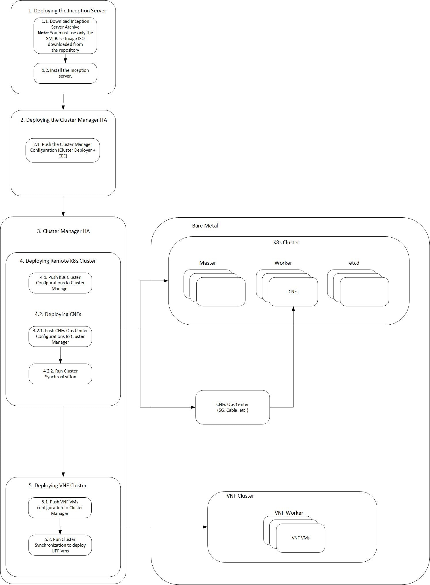
Sample Cluster Manager HA Configuration - OpenStack

The following is a sample HA configuration, which defines two HA nodes (Active and Standby) for OpenStack environments:


Important


When upgrading to Ubuntu 22.04, use routes gateway_address instead of gateway4 gateway_address in your network configuration.


 software cnf <software_version> #For example, cm-2020-02-0-i05 
 url <repo_url> 
 user <username> 
 password <password> 
 sha256 <sha256_hash> 
exit 
environments manual 
 manual 
exit 
clusters <cluster_name> #For example, cndp-testbed-cm 
 environment manual 
 addons ingress bind-ip-address <IPv4address> 
 addons cpu-partitioner enabled 
 configuration allow-insecure-registry true 
 node-defaults ssh-username <username> 
 node-defaults ssh-connection-private-key  
  "-----BEGIN OPENSSH PRIVATE KEY-----\n
 <SSH_private_key>
  -----END OPENSSH PRIVATE KEY-----\n"
 node-defaults initial-boot netplan ethernets <interface_name> #For example, eno1 
  dhcp4 false 
  dhcp6 false 
  gateway4 <IPv4address> 
  nameservers search <nameserver> 
  nameservers addresses <IPv4addresses> 
 exit 
 node-defaults initial-boot default-user <username>  
 node-defaults initial-boot default-user-ssh-public-key  
  "<SSH_Public_Key>"
 node-defaults initial-boot default-user-password #For example, Csco123# 
 node-defaults os proxy https-proxy <proxy_server_url> 
 node-defaults os proxy no-proxy <proxy_server_url/IPv4address>  
 node-defaults os ntp enabled 
 node-defaults os ntp servers <ntp_server>  
 exit 
 nodes control-plane 
  ssh-ip <IPv4address> node-defaults netplan template
  type k8s 
  k8s node-type control-plane 
  k8s node-labels <node_labels/node_type>  
  exit 
 cluster-manager enabled 
 cluster-manager repository-local <repo_name> #For example, cm-2020-02-0-i05 
 cluster-manager netconf-ip <IPv4address> 
 cluster-manager iso-download-ip <IPv4address> 
 cluster-manager initial-boot-parameters first-boot-password <password> #For example, 'Csco123#' 
exit 

Dual Stack Support

Dual stack enables networking devices to be configured with both IPv4 and IPv6 addresses. SMI supports certain subnets to be configured with dual stack within the remote Kubernetes cluster and the CM HA.

Dual Stack Support for Remote Kubernetes and CM HA

The host and the remote Kubernetes can be configured with the IPv6 address, by setting the ipv6-mode to dual-stack in the configuration file.

This section provides sample configurations for the SMI Management Cluster with Cluster Manager HA and CEE, and the remote Kubernetes with the pod subnet, service subnet and the docker subnet configured with IPv6 address.

The following are the default IPv6 addresses for the subnets:

  • The default IPv6 subnet for pod subnet is fd20::0/112

  • The default IPv6 subnet for service subnet is fd20::0/112

  • The default IPv6 CIDR for docker subnet is fd00::/80


Note


  • You must reset the cluster after upgrading an IPv4 cluster with dual stack.

  • The network interfaces that are configured using the clusters nodes k8s node-ip CLI command must have an IPv6 address.


For deployment information, see the SMI Cluster Manager in High Availability section.

Dual Stack Configuration for Remote Kubernetes

Prerequisites

The following are the prerequisites for deploying the remote Kubernetes cluster for dual stack configuration:

  • SMI Cluster Manager and CEE are deployed.

  • All the pods are running.

  • The network is configured to interact with the remote cluster CIN on both IPv4 and IPv6.

The following is the sample configuration for remote Kubernetes:


Important


When upgrading to Ubuntu 22.04, use routes gateway_address instead of gateway4 gateway_address in your network configuration.


software cnf cee
 url                            <repo_url>
 user                           <user>
 password                       <password>
 accept-self-signed-certificate false
 sha256                         <sha256_hash>
exit
software cnf cm
 url                            <url>
 user                           <username>
 password                       <password>
 accept-self-signed-certificate false
 sha256                         <sha256_hash>
exit
environments ucs
 ucs-server
exit
feature-gates alpha true
clusters tb16-2
 environment ucs
 vm-defaults upf software 74879
 vm-defaults upf networking management netmask 255.255.255.192
 vm-defaults upf networking management gateway 10.84.114.193
 vm-defaults upf networking management interface-type bridge
 vm-defaults upf networking management bridge name ex4000
 vm-defaults upf day0 username starent
 vm-defaults upf day0 password <password>
 vm-defaults upf day0 syslog-ip 10.192.1.101
 node-defaults ssh-username cloud-user
 node-defaults kvm fluent-forwarding host 10.192.1.59
 node-defaults kvm fluent-forwarding port 24224
 node-defaults kvm fluent-forwarding disable-tls true
 node-defaults initial-boot default-user cloud-user
 node-defaults initial-boot default-user-ssh-public-key <ssh_public_key>
 node-defaults initial-boot default-user-password <password>
 node-defaults initial-boot netplan ethernets eno5
  dhcp4 false
  dhcp6 false
 exit
 node-defaults initial-boot netplan ethernets eno6
  dhcp4 false
Aborted: by user
[upf-cm-tb16-2-cm1] SMI Cluster Deployer# show running-config clusters tb16-ipv6 
clusters tb16-ipv6
 environment ucs
 addons ingress bind-ip-address 10.84.114.206
 addons ingress bind-ip-address-internal 10.192.1.61
 addons cpu-partitioner enabled
 configuration master-virtual-ip        10.84.114.206
 configuration master-virtual-ip-interface vlan3540
 configuration additional-master-virtual-ip 10.192.1.61
 configuration additional-master-virtual-ip-interface vlan1001
 configuration ipv6-mode                dual-stack
 configuration pod-subnet               12.0.0.0/16
 configuration allow-insecure-registry  true
 configuration docker-address-pools pool1
  base 192.51.0.0/16
  size 24
 exit
 node-defaults ssh-username cloud-user
 node-defaults initial-boot default-user cloud-user
 node-defaults initial-boot default-user-ssh-public-key <ssh_public_key>
 node-defaults initial-boot default-user-password <password>
 node-defaults initial-boot netplan ethernets eno5
  dhcp4 false
  dhcp6 false
 exit
 node-defaults initial-boot netplan ethernets eno6
  dhcp4 false
  dhcp6 false
 exit
 node-defaults initial-boot netplan bonds bd0
  dhcp4      false
  dhcp6      false
  optional   true
  interfaces [ eno5 eno6 ]
  parameters mode      active-backup
  parameters mii-monitor-interval 100
  parameters fail-over-mac-policy active
 exit
 node-defaults initial-boot netplan vlans vlan1001
  dhcp4 false
  dhcp6 false
  id    1001
  link  bd0
 exit
 node-defaults k8s ssh-connection-private-key <ssh_connection_key>
 node-defaults ucs-server cimc user admin
 node-defaults ucs-server cimc password <password>
 node-defaults ucs-server cimc networking ntp enabled
 node-defaults ucs-server cimc networking ntp servers 192.200.0.29
 exit
 node-defaults os netplan-additions vlans vlan3540
  dhcp4    false
  dhcp6    false
  gateway4 10.84.114.193
  gateway6 2001:420:2c7f:f690::1
  nameservers search [ cisco.com ]
  nameservers addresses [ 10.84.96.130 64.102.6.247 161.44.124.122 ]
  id       3540
  link     bd0
 exit
 node-defaults os ntp enabled
 node-defaults os ntp servers ntp.esl.cisco.com
 exit
 nodes controlplane1
  ssh-ip 10.192.1.62
  type   k8s
  k8s node-type control-plane
  k8s ssh-ip   10.192.1.62
  k8s node-ip  10.192.1.62
  k8s ssh-username cloud-user
  k8s node-labels smi.cisco.com/node-type oam
  exit
  ucs-server cimc ip-address 192.100.0.6
  initial-boot netplan vlans vlan1001
   addresses [ 10.192.1.62/24 fd32:e985:ce1:fff2::106/64 ]
   routes 10.192.1.0/24 10.192.1.1
   exit
  exit
  os netplan-additions vlans vlan3540
   addresses [ 10.84.114.246/26 2001:420:2c7f:f690::f106/64 ]
  exit
 exit
 nodes controlplane2
  ssh-ip 10.192.1.63
  type   k8s
  k8s node-type control-plane
  k8s ssh-ip   10.192.1.63
  k8s node-ip  10.192.1.63
  k8s ssh-username cloud-user
  k8s node-labels smi.cisco.com/node-type oam
  exit
  ucs-server cimc ip-address 192.100.0.5
  initial-boot netplan vlans vlan1001
   addresses [ 10.192.1.63/24 fd32:e985:ce1:fff2::105/64 ]
   routes 10.192.1.0/24 10.192.1.1
   exit
  exit
  os netplan-additions vlans vlan3540
   addresses [ 10.84.114.248/26 2001:420:2c7f:f690::f105/64 ]
  exit
 exit
 nodes controlplane3
  ssh-ip 10.192.1.64
  type   k8s
  k8s node-type control-plane
  k8s ssh-ip   10.192.1.64
  k8s node-ip  10.192.1.64
  k8s ssh-username cloud-user
  k8s node-labels smi.cisco.com/node-type oam
  exit
  ucs-server cimc ip-address 192.100.0.4
  initial-boot netplan vlans vlan1001
   addresses [ 10.192.1.64/24 fd32:e985:ce1:fff2::104/64 ]
   routes 10.192.1.0/24 10.192.1.1
   exit
  exit
  os netplan-additions vlans vlan3540
   addresses [ 10.84.114.250/26 2001:420:2c7f:f690::f104/64 ]
  exit
 exit
 ops-centers cee voice
  repository-local cee
  initial-boot-parameters use-volume-claims true
  initial-boot-parameters first-boot-password <password>
  initial-boot-parameters auto-deploy true
  initial-boot-parameters single-node false
 exit
exit

Dual Stack Configuration for SMI Management Cluster with CM HA and CEE

Prerequisites

  • The management cluster is deployed comprising of the CM HA active and standby nodes and CEE.

  • Inception cluster manager is deployed

  • All the containers are running.

  • The network is configured to interact with the remote cluster CIN on both IPv4 and IPv6.

The following is the configuration for management cluster:


software cnf cee
 url                            <repo_url>
 user                           <username>
 password                       <password>
 accept-self-signed-certificate false
 sha256                         <sha256_hash
exit
software cnf cm
 url                            <repo_url>
 user                           <username>
 password                       <password>
 accept-self-signed-certificate false
 sha256                         <sha256_hash>
exit
environments ucs
 ucs-server
exit
feature-gates alpha true
clusters tb16-ipv6-ha
 environment ucs
 addons ingress bind-ip-address 10.84.114.206
 addons ingress bind-ip-address-internal 10.192.1.61
 addons cpu-partitioner enabled
 configuration master-virtual-ip        10.84.114.206
 configuration master-virtual-ip-interface vlan3540
 configuration additional-master-virtual-ip 10.192.1.61
 configuration additional-master-virtual-ip-interface vlan1001
 configuration ipv6-mode                dual-stack
 configuration pod-subnet               12.0.0.0/16
 configuration allow-insecure-registry  true
 configuration docker-address-pools pool1
  base 192.51.0.0/16
  size 24
 exit
 node-defaults ssh-username cloud-user
 node-defaults initial-boot default-user cloud-user
 node-defaults initial-boot default-user-ssh-public-key "<SSH_Public_Key>"
 node-defaults initial-boot default-user-password <user_password>
 node-defaults initial-boot netplan ethernets eno5
  dhcp4 false
  dhcp6 false
 exit
 node-defaults initial-boot netplan ethernets eno6
  dhcp4 false
  dhcp6 false
 exit
 node-defaults initial-boot netplan bonds bd0
  dhcp4      false
  dhcp6      false
  optional   true
  interfaces [ eno5 eno6 ]
  parameters mode      active-backup
  parameters mii-monitor-interval 100
  parameters fail-over-mac-policy active
 exit
 node-defaults initial-boot netplan vlans vlan1001
  dhcp4 false
  dhcp6 false
  id    1001
  link  bd0
 exit
 node-defaults k8s ssh-connection-private-key <ssh_connection_key>
 node-defaults ucs-server cimc user admin
 node-defaults ucs-server cimc password <password>
 node-defaults ucs-server cimc networking ntp enabled
 node-defaults ucs-server cimc networking ntp servers 192.200.0.29
 exit
 node-defaults os netplan-additions vlans vlan3540
  dhcp4    false
  dhcp6    false
  gateway4 10.84.114.193
  gateway6 2001:420:2c7f:f690::1
  nameservers search [ cisco.com ]
  nameservers addresses [ 10.84.96.130 64.102.6.247 161.44.124.122 ]
  id       3540
  link     bd0
 exit
 node-defaults os ntp enabled
 node-defaults os ntp servers ntp.esl.cisco.com
 exit
 nodes controlplane1
  ssh-ip 10.192.1.62
  type   k8s
  k8s node-type control-plane
  k8s node-ip  10.192.1.61
  k8s ssh-username cloud-user
  k8s node-labels smi.cisco.com/node-type oam
  exit
  ucs-server cimc ip-address 192.100.0.6
  initial-boot netplan vlans vlan1001
   addresses [ 10.192.1.62/24 fd32:e985:ce1:fff2::106/64 ]
   routes 10.192.1.0/24 10.192.1.1
   exit
  exit
  os netplan-additions vlans vlan3540
   addresses [ 10.84.114.246/26 2001:420:2c7f:f690::f106/64 ]
  exit
 exit
 nodes controlplane2
  ssh-ip 10.192.1.63
  type   k8s
  k8s node-type backup
  k8s node-ip  10.192.1.61
  k8s ssh-username cloud-user
  k8s node-labels smi.cisco.com/node-type oam
  exit
  ucs-server cimc ip-address 192.100.0.5
  initial-boot netplan vlans vlan1001
   addresses [ 10.192.1.63/24 fd32:e985:ce1:fff2::105/64 ]
   routes 10.192.1.0/24 10.192.1.1
   exit
  exit
  os netplan-additions vlans vlan3540
   addresses [ 10.84.114.248/26 2001:420:2c7f:f690::f105/64 ]
  exit
 exit
 cluster-manager enabled
 cluster-manager repository-local cm
 cluster-manager netconf-port 831
 cluster-manager ssh-port 2023
 cluster-manager initial-boot-parameters first-boot-password <password>
 ops-centers cee voice
  repository-local cee
  initial-boot-parameters use-volume-claims true
  initial-boot-parameters first-boot-password <password>
  initial-boot-parameters auto-deploy true
  initial-boot-parameters single-node false
 exit
exit

Note


To improve scalability, if you must switch to PCIe from an mLOM card, where the K8s internal network is on VLAN 107, change the network bond value from bd0 to bd1.

Considering that the CEE and SMF are shut down, you must only move the VIP from bd0 to bd1 without changing the IP subnet.


SMI Cluster Manager in All-In-One Mode

This section provides information about deploying the SMI Cluster Manager in All-In-One (AIO).

Prerequisites

The following are the prerequisites for deploying the SMI Cluster Manager:

  • An Inception Deployer that has deployed the Cluster Manager.

  • The SMI Cluster Manager that has deployed the CEE cluster.

Minimum Hardware Requirements - Bare Metal

The minimum hardware requirements for deploying the SMI Cluster Manager on Bare Metal are:

Table 6. Minimum Hardware Requirements - Bare Metal
Deployment Model Nodes Server Type Networking

NIC

Cores Per Socket
Linux K8s CEE
All-in-One (AIO) All Nodes

Cisco UCS C220 M5/M6/M7

Cisco Catalyst 3850 and Cisco Nexus 9000 Series Switches

Cisco UCS C220 M5/M6/M7:

  • Intel® Ethernet Network Adapter E810-CQDA2

  • Intel® Network Adapter XL710

  • Intel® Network Adapter X710

  • Intel® Ethernet Controller XXV710

  • NVIDIA ConnectX-5|

  • Intel® X520

  • Intel® Ethernet Controller 82599ES

  • Intel® Ethernet Network Adapter E810

2 cores 2 cores 4 cores

Note


You must install a RAID Controller such as Cisco 12 Gbps modular RAID controller with 2 GB cache module on the UCS server for the cluster sync operation to function properly. For RAID 1, you must install a minimum of 2 SSDs to improve the read and write access speed.


Supported Configurations - VMware

The SMI Cluster Manager supports the following VM configurations:


Note


Individual NFs are deployed as K8s workers through SMI. They each have their own VM recommendations. Refer to the NF documentation for details.


Table 7. Supported Configurations - VMware
Nodes CPU Cores Per Socket RAM Data Disk Home Disk Root Disk
Control Plane 2 CPU 2 16 GB 20 GB 5 GB 100 GB
ETCD 2 CPU 2 16 GB 20 GB 5 GB 100 GB
Worker 36 CPU 36 164 GB 200 GB 5 GB 100 GB

Deploying the SMI Cluster Manager in AIl-In-One Mode

You can deploy the SMI Cluster Manager using the Inception Server on AIO mode. To deploy the SMI Cluster Manager:

  1. Login to the Inception Server and enter the configuration mode.

    • Add the configuration SMI Cluster Manager AIO configuration.


      Note


      • For deploying a single node SMI Cluster Manager on Bare Metal, add the SMI Cluster Manager AIO configuration defined for Bare Metal environments. A sample SMI Cluster Manager AIO configuration for Bare Metal environments is provided here.

      • For deploying a single node SMI Cluster Manager on VMware, add the SMI Cluster Manager AIO configuration defined for VMware environments. A sample SMI Cluster Manager AIO configuration for VMware environments is provided here.

      • For deploying a single node SMI Cluster Manager on VMware, add the SMI Cluster Manager AIO configuration defined for OpenStack environments. A sample SMI Cluster Manager AIO configuration for OpenStack environments is provided here.


    • Commit and exit the configuration

  2. Run the cluster synchronization

    clusters cluster_name actions sync run debug true
     
    • Monitor the progress of the synchronization

      monitor sync-logs cluster_name 

      Note


      The synchronization completes after 30 minutes approximately. The time taken for synchronization is based on network factors such as network speed, and VM power.


  3. Connect to the SMI Cluster Manager CLI after the synchronization completes

    ssh admin@cli.smi-cluster-deployer.<ipv4address>.<domain_name> -p <port_number> 

NOTES:

  • clusters cluster_name – Specifies the information about the nodes to be deployed. cluster_name is the name of the cluster.

  • actions – Specifies the actions performed on the cluster.

  • sync run – Triggers the cluster synchronization.

  • monitor sync-logs cluster_name - Monitors the cluster synchronization.

Sample Cluster Manager AIO Configuration - Bare Metal

This section shows sample configurations to set up a single node Cluster Manager on bare metal servers.

Cisco UCS Server


Important


When upgrading to Ubuntu 22.04, use routes gateway_address instead of gateway4 gateway_address in your network configuration.


 software cnf <software_version> #For example, cm-2020-02-0-i05 
 url <repo_url> 
 user <username> 
 password <password> 
 sha256 <sha256_hash> 
exit 
environments bare-metal 
 ucs-server 
exit 
clusters <cluster_name> #For example, cndp-testbed-cm 
 environment bare-metal 
 addons ingress bind-ip-address <IPv4address> 
 addons cpu-partitioner enabled 
 configuration allow-insecure-registry true 
 node-defaults ssh-username <username> 
 node-defaults ssh-connection-private-key  
  "-----BEGIN OPENSSH PRIVATE KEY-----\n
 <SSH_private_key>
  -----END OPENSSH PRIVATE KEY-----\n"
 node-defaults initial-boot netplan ethernets <interface_name> #For example, eno1 
  dhcp4 false 
  dhcp6 false 
  gateway4 <IPv4address> 
  nameservers search <nameserver> 
  nameservers addresses <IPv4addresses> 
 exit 
 node-defaults initial-boot default-user <username>  
 node-defaults initial-boot default-user-ssh-public-key  
  "<SSH_Public_Key>"
 node-defaults initial-boot default-user-password #For example, Csco123# 
 node-defaults os proxy https-proxy <proxy_server_url> 
 node-defaults os proxy no-proxy <proxy_server_url/IPv4address>  
 node-defaults os ntp enabled 
 node-defaults os ntp servers <ntp_server>  
 exit 
 nodes control-plane 
  ssh-ip <IPv4address> node-defaults netplan template
  type k8s 
  k8s node-type control-plane 
  k8s node-labels <node_labels/node_type>  
  exit 
  ucs-server host initial-boot networking static-ip ipv4-address <IPv4address> 
  ucs-server host initial-boot networking static-ip netmask <IPv4address> 
  ucs-server host initial-boot networking static-ip gateway <IPv4address> 
  ucs-server host initial-boot networking static-ip dns <IPv4address> 
  ucs-server cimc ip-address <IPv4address> 
  ucs-server cimc user <username> #For example, admin 
  ucs-server cimc password <password> #For example, C1sc0123# 
  ucs-server cimc storage-adaptor create-virtual-drive true 
  ucs-server cimc networking ntp enabled 
  ucs-server cimc networking ntp servers <ntp_server_url>  
  initial-boot netplan ethernets <interface_name> #For example, eno1 
   addresses <IPv4address/subnet> 
  exit 
 exit 
 cluster-manager enabled 
 cluster-manager repository-local <repo_name> #For example, cm-2020-02-0-i05 
 cluster-manager netconf-ip <IPv4address> 
 cluster-manager iso-download-ip <IPv4address> 
 cluster-manager initial-boot-parameters first-boot-password <password> #For example, 'Csco123#' 
exit 

Sample Cluster Manager AIO Configuration - VMware

The following is a sample configuration for a single node Cluster Manager on VMware vCenter:

clusters <cluster_name> 
 
         # associating an existing vcenter environment 
         environment <vcenter_environment> #Example:laas 
 
         # General cluster configuration 
         configuration master-virtual-ip <keepalived_ipv4_address>  
         configuration master-virtual-ip-cidr <netmask_of_additional_master_virtual_ip> #Default is 32   
         configuration master-virtual-ip-interface <interface_name>  
         configuration additional-master-virtual-ip <ipv4_address>  
         configuration additional-master-virtual-ip-cidr <netmask_of_additional_master_virtual_ip> #Default is 32  
         configuration additional-master-virtual-ip-interface <interface_name> 
         configuration virtual-ip-vrrp-router-id <virtual_router_id> #To support multiple instances of VRRP in the same subnet 
         configuration pod-subnet <pod_subnet> #To avoid conflict with already existing subnets  
         configuration size <functional_test_ha/functional_test_aio/production>  
         configuration allow-insecure-registry <true> #To allow insecure registries 
 
        # istio and nginx ingress addons 
         addons ingress bind-ip-address <keepalived_ipv4_address>  
         addons istio enabled 
 
         # vsphere volume provider configuration 
         addons vsphere-volume-provider server <vcenter_server_ipv4_address>  
         addons vsphere-volume-provider server-port <vcenter_port> 
         addons vsphere-volume-provider allow-insecure <true> #To allow self signed certs  
         addons vsphere-volume-provider user <vcenter_username> 
         addons vsphere-volume-provider password <vcenter_password> 
         addons vsphere-volume-provider datacenter <vcenter_datacenter> 
         addons vsphere-volume-provider datastore <vcenter_nfs_storage> #Corresponding vcenter nfs storage 
         addons vsphere-volume-provider network <network_id> 
         addons vsphere-volume-provider folder <cluster_folder_containing_the_VMs> 
 
         # Openstack volume provider configuration 
         addons openstack-volume-provider username <username>  
         addons openstack-volume-provider password <password>  
         addons openstack-volume-provider auth-url <auth_url>  
         addons openstack-volume-provider tenant-id <tenant_id>  
         addons openstack-volume-provider domain-id <domain_id> 
 
         # initial-boot section of node-defaults for vmware 
         node-defaults initial-boot default-user <default_username>  
         node-defaults initial-boot default-user-ssh-public-key <public_ssh_key> 
         node-defaults initial-boot netplan template 

 
         # initial-boot section of node-defaults for VMs managed in Openstack 
         node-defaults initial-boot default-user <default_user> 
         node-defaults netplan template 
           #jinja2:variable_start_string:'__DO_NOT_ESCAPE__' , variable_end_string:'__DO_NOT_ESCAPE__' 
           # 
 
         #k8s related config of node-defaults 
         node-defaults k8s ssh-username <default_k8s_ssh_username>  
         node-defaults k8s ssh-connection-private-key 
                 -----BEGIN RSA PRIVATE KEY----- 
                 <SSH_Private_Key> 
                 -----END RSA PRIVATE KEY----- 
 
           # os related config of node-defaults 
           node-defaults os proxy https-proxy <https_proxy>  
           node-defaults os proxy no-proxy <no_proxy_info>  
           node-defaults os ntp servers <local_ntp_server> 
           exit 
 
           # node configuration of multinode cluster. vmware related info overrides the defaults provided in the environment 'laas' associated with the cluster 
 
      nodes node_name #For example, etcd1 
         k8s node-type etcd 
         k8s ssh-ip ipv4address 
         k8s node-ip ipv4address 
         vmware datastore datastore_name 
         vmware host host_name 
         vmware performance latency-sensitivity normal 
         vmware performance memory-reservation false 
         vmware performance cpu-reservation false 
         vmware sizing ram-mb ram_size_in_mb 
         vmware sizing cpus cpu_size 
         vmware sizing disk-root-gb disk_root_size_in_gb 
         vmware nics network_ID 
      exit 
   exit 
   nodes node_name #For example, etcd2 
       k8s node-type etcd 
       k8s ssh-ip ipv4address 
       k8s node-ip ipv4address 
       vmware datastore datastore_name 
       vmware host host_name 
       vmware performance latency-sensitivity normal 
       vmware performance memory-reservation false 
       vmware performance cpu-reservation false 
       vmware sizing ram-mb ram_size_in_mb 
       vmware sizing cpus cpu_size 
       vmware sizing disk-root-gb disk_root_size_in_gb 
       vmware nics network_ID 
     exit 
   exit 
   nodes node_name #For example, etcd3 
       k8s node-type etcd 
       k8s ssh-ip ipv4address 
       k8s node-ip ipv4address 
       vmware datastore datastore_name 
       vmware host host_name 
       vmware performance latency-sensitivity normal 
       vmware performance memory-reservation false 
       vmware performance cpu-reservation false 
       vmware sizing ram-mb ram_size_in_mb 
       vmware sizing cpus cpu_size 
       vmware sizing disk-root-gb disk_root_size_in_gb 
       vmware nics network_ID 
     exit 
   exit 
   nodes node_name #For example, controlplane1 
       k8s node-type control-plane 
       k8s ssh-ip ipv4address 
       k8s node-ip ipv4address 
       vmware datastore datastore_name 
       vmware host host_name 
       vmware performance latency-sensitivity normal 
       vmware performance memory-reservation false 
       vmware performance cpu-reservation false 
       vmware sizing ram-mb ram_size_in_mb 
       vmware sizing cpus cpu_size 
       vmware sizing disk-root-gb disk_root_size_in_gb 
       vmware nics network_ID 
      exit 
   exit 
   nodes node_name #For example, controlplane2 
      k8s node-type control-plane 
      k8s ssh-ip ipv4address 
      k8s node-ip ipv4address 
      vmware datastore datastore_name 
      vmware host host_name 
      vmware performance latency-sensitivity normal 
      vmware performance memory-reservation false 
      vmware performance cpu-reservation false 
      vmware sizing ram-mb ram_size_in_mb 
      vmware sizing cpus cpu_size 
      vmware sizing disk-root-gb disk_root_size_in_gb 
      vmware nics network_ID 
      exit 
    exit 
   nodes node_name #For example, controlplane3 
      k8s node-type control-plane 
      k8s ssh-ip ipv4address 
      k8s node-ip ipv4address 
      vmware datastore datastore_name 
      vmware host host_name 
      vmware performance latency-sensitivity normal 
      vmware performance memory-reservation false 
      vmware performance cpu-reservation false 
      vmware sizing ram-mb ram_size_in_mb 
      vmware sizing cpus cpu_size 
      vmware sizing disk-root-gb disk_root_size_in_gb 
      vmware nics network_ID 
      exit 
   exit 
   nodes node_name #For example, oam1 
      k8s node-type worker 
      k8s ssh-ip ipv4address 
      k8s node-ip ipv4address 
      k8s node-labels node_labels 
      exit 
      vmware datastore datastore_name 
      vmware host host_name 
      vmware performance latency-sensitivity normal 
      vmware performance memory-reservation false 
      vmware performance cpu-reservation false 
      vmware sizing ram-mb ram_size_in_mb 
      vmware sizing cpus cpu_size 
      vmware sizing disk-root-gb disk_root_size_in_gb 
      vmware nics network_ID 
      exit 
   exit 
   nodes node_name #For example, oam2 
      k8s node-type worker 
      k8s ssh-ip ipv4address 
      k8s node-ip ipv4address 
      k8s node-labels node_labels 
      exit 
      vmware datastore datastore_name 
      vmware host host_name 
      vmware performance latency-sensitivity normal 
      vmware performance memory-reservation false 
      vmware performance cpu-reservation false 
      vmware sizing ram-mb ram_size_in_mb 
      vmware sizing cpus cpu_size 
      vmware sizing disk-root-gb disk_root_size_in_gb 
      vmware nics network_ID 
      exit 
   exit 
   nodes node_name #For example, oam3 
      k8s node-type worker 
      k8s ssh-ip ipv4address 
      k8s node-ip ipv4address 
      k8s node-labels node_labels 
      exit 
      vmware datastore datastore_name 
      vmware host host_name 
      vmware performance latency-sensitivity normal 
      vmware performance memory-reservation false 
      vmware performance cpu-reservation false 
      vmware sizing ram-mb ram_size_in_mb 
      vmware sizing cpus cpu_size 
      vmware sizing disk-root-gb disk_root_size_in_gb 
      vmware nics network_ID 
      exit 
   exit 
   nodes node_name #For example, session-data1 
      k8s node-type worker 
      k8s ssh-ip ipv4address 
      k8s node-ip ipv4address 
      k8s node-labels node_labels #For example, smi.cisco.com/cdl-ep true 
      exit 
      k8s node-labelsnode_labels #For example, smi.cisco.com/cdl-index-1 true 
      exit 
      k8s node-labelsnode_labels #For example, smi.cisco.com/cdl-index-2 true 
      exit 
      k8s node-labelsnode_labels #For example, smi.cisco.com/cdl-slot-1 true 
      exit 
      k8s node-labelsnode_labels #For example, smi.cisco.com/cdl-slot-2 true 
      exit 
      k8s node-labelsnode_labels #For example, smi.cisco.com/cdl-slot-3 true 
      exit 
      k8s node-labelsnode_labels #For example, smi.cisco.com/cdl-slot-4 true 
      exit 
      k8s node-labelsnode_labels/node_type #For example, smi.cisco.com/node-type db 
      exit 
      k8s node-labelsnode_labels/vm_type #For example, smi.cisco.com/vm-type session 
      exit 
      vmware datastore datastore_name 
      vmware host host_name 
      vmware performance latency-sensitivity normal 
      vmware performance memory-reservation false 
      vmware performance cpu-reservation false 
      vmware sizing ram-mb ram_size_in_mb 
      vmware sizing cpus cpu_size 
      vmware sizing disk-root-gb disk_root_size_in_gb 
      vmware nics network_ID 
      exit 
    exit 
    nodes node_name #For example, session-data2 
      k8s node-type worker 
      k8s ssh-ip ipv4address 
      k8s node-ip ipv4address 
      k8s node-labels node_labels #For example, smi.cisco.com/cdl-ep true 
      exit 
      k8s node-labelsnode_labels #For example, smi.cisco.com/cdl-index-1 true 
      exit 
      k8s node-labelsnode_labels #For example, smi.cisco.com/cdl-index-2 true 
      exit 
      k8s node-labelsnode_labels #For example, smi.cisco.com/cdl-slot-1 true 
      exit 
      k8s node-labelsnode_labels #For example, smi.cisco.com/cdl-slot-2 true 
      exit 
      k8s node-labelsnode_labels #For example, smi.cisco.com/cdl-slot-3 true 
      exit 
      k8s node-labelsnode_labels #For example, smi.cisco.com/cdl-slot-4 true 
      exit 
      k8s node-labelsnode_labels/node_type #For example, smi.cisco.com/node-type db 
      exit 
      k8s node-labelsnode_labels/vm_type #For example, smi.cisco.com/vm-type session 
      exit 
      vmware datastore datastore_name 
      vmware host host_name 
      vmware performance latency-sensitivity normal 
      vmware performance memory-reservation false 
      vmware performance cpu-reservation false 
      vmware sizing ram-mb ram_size_in_mb 
      vmware sizing cpus cpu_size 
      vmware sizing disk-root-gb disk_root_size_in_gb 
      vmware nics network_ID 
      exit 
   exit 
   nodes node_name #For example, session-data3 
      k8s node-type worker 
      k8s ssh-ip ipv4address 
      k8s node-ip ipv4address 
      k8s node-labels node_labels #For example, smi.cisco.com/cdl-ep true 
      exit 
      k8s node-labelsnode_labels #For example, smi.cisco.com/cdl-index-3 true 
      exit 
      k8s node-labelsnode_labels #For example, smi.cisco.com/cdl-index-4 true 
      exit 
      k8s node-labelsnode_labels #For example, smi.cisco.com/cdl-slot-5 true 
      exit 
      k8s node-labelsnode_labels #For example, smi.cisco.com/cdl-slot-6 true 
      exit 
      k8s node-labelsnode_labels #For example, smi.cisco.com/cdl-slot-7 true 
      exit 
      k8s node-labelsnode_labels #For example, smi.cisco.com/cdl-slot-8 true 
      exit 
      k8s node-labelsnode_labels/node_type #For example, smi.cisco.com/node-type db 
      exit 
      k8s node-labelsnode_labels/vm_type #For example, smi.cisco.com/vm-type session 
      exit 
      vmware datastore datastore_name 
      vmware host host_name 
      vmware performance latency-sensitivity normal 
      vmware performance memory-reservation false 
      vmware performance cpu-reservation false 
      vmware sizing ram-mb ram_size_in_mb 
      vmware sizing cpus cpu_size 
      vmware sizing disk-root-gb disk_root_size_in_gb 
      vmware nics network_ID 
      exit 
    exit 
    nodes node_name #For example, session-data4 
      k8s node-type worker 
      k8s ssh-ip ipv4address 
      k8s node-ip ipv4address 
      k8s node-labels node_labels #For example, smi.cisco.com/cdl-ep true 
      exit 
      k8s node-labelsnode_labels #For example, smi.cisco.com/cdl-index-3 true 
      exit 
      k8s node-labelsnode_labels #For example, smi.cisco.com/cdl-index-4 true 
      exit 
      k8s node-labelsnode_labels #For example, smi.cisco.com/cdl-slot-5 true 
      exit 
      k8s node-labelsnode_labels #For example, smi.cisco.com/cdl-slot-6 true 
      exit 
      k8s node-labelsnode_labels #For example, smi.cisco.com/cdl-slot-7 true 
      exit 
      k8s node-labelsnode_labels #For example, smi.cisco.com/cdl-slot-8 true 
      exit 
      k8s node-labelsnode_labels/node_type #For example, smi.cisco.com/node-type db 
      exit 
      k8s node-labelsnode_labels/vm_type #For example, smi.cisco.com/vm-type session 
      exit 
      vmware datastore datastore_name 
      vmware host host_name 
      vmware performance latency-sensitivity normal 
      vmware performance memory-reservation false 
      vmware performance cpu-reservation false 
      vmware sizing ram-mb ram_size_in_mb 
      vmware sizing cpus cpu_size 
      vmware sizing disk-root-gb disk_root_size_in_gb 
      vmware nics network_ID 
      exit 
   exit 
exit 
           # Virtual IPs 
          virtual-ips <name> #Example: rxdiam 

            vrrp-interface <interface_name> 
            vrrp-router-id <router_id> 

            ipv4-addresses <ipv4_address> 
              mask <netmassk> 
              broadcast <broadcast_ipv4_address> 
              device <interface_name> 
            exit 
            # nodes associated with the virtual-ip 
            hosts <node_name> #Example: smi-cluster-core-protocol1 
              priority <priority_value> 
            exit 
            hosts <node_name> #Example: smi-cluster-core-protocol2 
              priority <priority_value> 
            exit 
          exit 
           # Secrets for product registry 
          secrets docker-registry <secret_name> 
            docker-server <server_name or docker_registry> 
            docker-username <username> 
            docker-password <password> 
            docker-email <email> 
            namespace <k8s_namespace> #Example: cee-voice 
          exit 
          ops-centers <app_name> <instance_name> #Example: cee data 
            repository <artifactory_url>  


            username <username> 
            password <password> 

            initial-boot-parameters use-volume-claims <true/false> #True to use persistent volumes and vice versa 
            initial-boot-parameters first-boot-password <password> #First boot password for product opscenter 
            initial-boot-parameters auto-deploy <true/false> #Auto deploys all the services of the product else deploys the opscenter only 
            initial-boot-parameters single-node <true/false> #True for single node and false for multi node deployments 
            initial-boot-parameters image-pull-secrets <docker_registry_secrets_name> 
            exit 
          exit 

Sample Cluster Manager AIO Configuration - OpenStack

The following is a sample configuration for a single node Cluster Manager on OpenStack environment:


Important


When upgrading to Ubuntu 22.04, use routes gateway_address instead of gateway4 gateway_address in your network configuration.


 software cnf <software_version> #For example, cm-2020-02-0-i05 
 url <repo_url> 
 user <username> 
 password <password> 
 sha256 <sha256_hash> 
exit 
environments manual 
 manual 
exit 
clusters <cluster_name> #For example, cndp-testbed-cm 
 environment manual 
 addons ingress bind-ip-address <IPv4address> 
 addons cpu-partitioner enabled 
 configuration allow-insecure-registry true 
 node-defaults ssh-username <username> 
 node-defaults ssh-connection-private-key  
  "-----BEGIN OPENSSH PRIVATE KEY-----\n
 <SSH_private_key>
  -----END OPENSSH PRIVATE KEY-----\n"
 node-defaults initial-boot netplan ethernets <interface_name> #For example, eno1 
  dhcp4 false 
  dhcp6 false 
  gateway4 <IPv4address> 
  nameservers search <nameserver> 
  nameservers addresses <IPv4addresses> 
 exit 
 node-defaults initial-boot default-user <username>  
 node-defaults initial-boot default-user-ssh-public-key  
  "<SSH_Public_Key>"
 node-defaults initial-boot default-user-password #For example, Csco123# 
 node-defaults os proxy https-proxy <proxy_server_url> 
 node-defaults os proxy no-proxy <proxy_server_url/IPv4address>  
 node-defaults os ntp enabled 
 node-defaults os ntp servers <ntp_server>  
 exit 
 nodes control-plane 
  ssh-ip <IPv4address> node-defaults netplan template
  type k8s 
  k8s node-type control-plane 
  k8s node-labels <node_labels/node_type>  
  exit 
 cluster-manager enabled 
 cluster-manager repository-local <repo_name> #For example, cm-2020-02-0-i05 
 cluster-manager netconf-ip <IPv4address> 
 cluster-manager iso-download-ip <IPv4address> 
 cluster-manager initial-boot-parameters first-boot-password <password> #For example, 'Csco123#' 
exit 

Cluster Manager Pods

A pod is a process that runs on your Kubernetes cluster. Pod encapsulates a granular unit that is known as a container. A pod contains one or multiple containers.

Kubernetes deploys one or multiple pods on a single node which can be a physical or virtual machine. Each pod has a discrete identity with an internal IP address and Port space. However, the containers within a pod can share the storage and network resources.

The following table lists the Cluster Manager (CM) pod names and their descriptions.

Table 8. CM Pods
Pod Name Description

cluster-files-offline-smi-cluster-deployer

Hosts all the necessary software that is locally required for successfully provisioning the remote Kubernetes clusters or UPF clusters. This pod in part enables a complete offline orchestration of the remote clusters.

ops-center-smi-cluster-deployer

Deployer operations center that can take in the required config for baremetal and/or VM Kubernetes clusters and provision it. It also accepts software inputs to spawn the required network functions on the appropriate clusters with day 0 configuration.

squid-proxy

Squid is a caching and forwarding HTTP web proxy. It has wide variety of uses, including speeding up a web server by caching repeated requests, caching web, DNS and other lookups, and aiding security by filtering traffic.