IMS PDU Sessions for Voice

Feature Summary and Revision History

Summary Data

Table 1. Summary Data

Applicable Product(s) or Functional Area

SMF

Applicable Platform(s)

SMI

Feature Default Setting

Disabled – Configuration Required

Related Changes in this Release

Not Applicable

Related Documentation

Not Applicable

Revision History

Table 2. Revision History

Revision Details

Release

Added support for VoLTE and Emergency Call Prioritization

2021.02.03

Introduced NPLI support for VoLTE and VoNR

2021.02.0

First introduced.

Pre-2020.02.0

Feature Description

This chapter provides an overview of the IMS procedures handeled by SMF.

Voice Over LTE Support

Feature Description


Important


The PGW-C term used in this chapter denotes the EPS interworking functionality supported by SMF and must not be assumed as a standalone P-GW that is used in the LTE network.


The SMF supports Voice over Long-Term Evolution or LTE (VoLTE). The VoLTE technology utilizes IP Multimedia Subsystem (IMS) to allow you to make cellular calls over the LTE access network.

SMF supports prioritization of emergency and VoLTE calls during ICSR switchover and recovery. The SMF tracks IMS sessions with active voice calls and communicates with UPF. Then, UPF prioritizes the Emergency and VoLTE calls during ICSR switchover and recovery. SMF supports only the Wireless Priority Services (WPS) call prioritization where the MP flag is configured in N4 and the GTP headers are based on the WPS configuration.

How it Works

A 5G mobile device with LTE access requests voice services to communicate with PGW-C over S-GW and MME resulting in the establishment of a PDU session. The PGW-C supports a non-GBR bearer with QCI flows as 5 for VoLTE sessions. This support allows IMS signaling along with P-CSCF, DNS IPv4, or DNS IPv6 addresses for end users. For mobile-originated (MO) or mobile-terminated (MT) calls, the Application Function (AF) provides policy authorization details to the PCF. The PCF then converts these details to GBR flows and PCC rules and sends them to PGW-C. The PGW-C then converts the GBR-flows to dedicated bearers by establishing the dedicated bearer creation procedure with UE (User Equipment). The PGW-C provisions the GBR with the QCI flow as 1 to UPF. By this provisioning, the UPF supports voice communication between the calling and called devices over IMS network elements.

As per the E-UTRAN Attach procedure, the MME triggers the GTPv2 Create Session Request to PGW-C over S-GW. This request includes the EPS Bearer Identity (EBI) value, ePCO options for P-CSCF and DNS IPv4 or DNS IPv6 containers, PDN-Type, and PAA options for IPv4 or IPv6 allocated address for end users. The PGW-C then processes the received Create Session Request and communicates with various SBI interfaces to receive the following information:

  • Subscription data from UDM by including PGW-C FQDN in the subscription request.

  • Policy information from PCF by sending SM policy create request. Policy information includes details, such as PCC rules and Session-AMBR.

  • Online and offline charging information from CHF by sending the charging create data request.

After communication with SBI interfaces, which are based on the local SMF profile configuration, the PGW-C sends the GTPv2 Create Session Response to the end user over S-GW and MME. This response includes:

  • PAA with IPv4 or IPv6 addresses that PGW-C IPAM module allocates

  • ePCO option with P-CSCF

  • DNS IPv4 or DNS IPv6 address based on DNN-Profile configuration

  • Non-GRB with the QCI flow as 5 for IMS signaling

For an MO or MT call, if the PCF is provisioned for GBR with the QCI flow as 1 for end users, the PGW-C converts these GBR flows to the dedicated bearer creation. The GBR flows include the flow information and the PCC rules in the SM Policy Update Notify Request. The dedicated bearer is created by sending GTPv2 Create Bearer Request to UE over S-GW or MME. Another S5-U tunnel is created between S-GW and PGW-C to allow GBE flow packets for the voice communication between the calling and called devices.

For prioritization of emergency and VoLTE calls during ICSR switchover and recovery, SMF includes the MP flag value in N4 and GTP messages. The flag values are listed in the following table.

Table 3. MP Flag Values

Call Type

MP Flag Value

Emergency

1

IMS-Active

2

IMS-Inactive

3

WPS

1


Note


  • If message-priority gtpc is configured in WPS profile, then SMF sends the MP flag value as 1 for the WPS sessions. Earlier SMF used to send MP value as 0 in N4 and GTP header for WPS sessions.

  • If a call matches multiple call types, then SMF sends better priority, which is the lowest value. If the call matches with WPS and the message-priority is not configured, then message priority is not sent.

  • SMF marks session as IMS-inactive when dedicated bearer or modify procedure starts for establishment of QCI configured as IMS in DNN profile and the session is not marked as IMS-active.

  • SMF updates the session as IMS-active session after the IMS QCI bearer or flow is established.

  • SMF updates the session as IMS-inactive session after last IMS QCI bearer or flow is deleted.

  • SMF marks session as WPS session when dedicated bearer or modify procedure starts for an ARP that is configured in WPS profile.

  • SMF updates the session as WPS session after WPS bearer or flow is established.

  • SMF updates the session as IMS-active or IMS-inactive if an IMS QCI bearer exists when the last WPS bearer was deleted.

  • SMF updates the session as IMS-inactive, if an IMS flow is removed during handover, path-switch, or any other procedure.

  • Clear subscriber non-VoLTE CLI implementation is modified to use the QCI that is configured as IMS. If QCI is not configured, the earlier behavior of detecting non-VoLTE session is used. This behaviour implies that the session does not having bearer or flows with QCI as 1 or 2.


Call Flows

This section describes the following call flows:

  • VoLTE PDU Session Creation Call Flow

  • VoLTE Mobile-Originated (MO) Call Creation Call Flow

  • VoLTE Mobile-Terminated (MT) Call Creation Call Flow

VoLTE PDU Session Creation Call Flow

To enable the connectivity through a 5G core, the initial attach on the E-UTRAN or EPS deviates from the defined 3GPP procedures in the following ways:

  • An SMF+PGW-C replaces the PGW-C in the procedure.

  • The SM Policy Association Establishment procedure replaces the IP-CAN Session Establishment and modification.

  • The integrated charging over the NCHF interface with CHF replaces the online and offline charging functionality by using the Gy and Gz interfaces.

  • Communication with the User Plane node happens over the N4 interface instead of the Sxb interface.


Note


Depending on the mapped PCC rules, the SMF+PGW-C can initiate the dedicated bearer creation.


The following call flow depicts the creation of a VoLTE PDU session.

Figure 1. VoLTE PDU Session Creation Call Flow
Table 4. VoLTE PDU Session Creation Call Flow Description
Step Description
1 UE sends the attach request to MME through eNodeB.
2 MME determines if the UE is active and subscribed for the handoff to NR. Then, MME selects a SMF+PGW-C node as the PGW-C for the PDU session.
3 MME sends the create session request to the selected S-GW and includes the selected SMF+PGW-C address in the request.
4

S-GW initiates the create session request toward SMF+PGW-C by including the “P-CSCF IPv4 or IPv6 request” container identifier in the extended PCO IE options.

SMF+PGW-C extracts and saves the PDU session ID that UE sends in the PCO option. Then, SMF+PGW-C performs a UDM registration and sends both the N11 and S5 or S8 interface ID to UDM. Based on the local configuration or the session management subscription data, which is received from UDM for respective DNN, SMF+PGW-C determines to support “IMS Voice over PS”.

5

SMF+PGW-C sends the NPCF SM policy control creation request to PCF to initiate the SM policy association establishment procedure. In this procedure, PGW-C+SMF includes the information elements that are received in the create session request message into the Npcf_SMPolicyControl_Create service. These elements comprise the following information:

  • SUPI contains the IMSI.

  • DNN contains the APN.

  • PEI contains the IMEI-SV.

  • Session AMBR contains the APN-AMBR.

  • Default QoS information that contains the default EPS bearer QoS. The QCI values are mapped into 5QI values.

6 PGW-C+SMF receives the PCC rules, PDU session policy information, and 5G QoS information. The PCC rules are mapped into EPS QoS information. The SMF+PGW-C creates TFT from the SDF filters that are received in the PCC rules. Then, SMF+PGW-C associates them with the corresponding default and dedicated bearers.
7 Based on the charging policies received from the PCF, the SMF+PGW-C initiates the NCHF converged charging creation procedure toward CHF. This procedure is based on the charging rules that are received from the PCF.
8 The SMF+PGW-C starts the UPF+PGW-U selection and N4 session establishment procedure. As this session is a 4G session that connects to the SMF+PGW-C, a separate CN tunnel is created for each bearer. Also, the QoS Flow Identifier (QFI) is not sent in the QoS Enforcement Rule (QER) and Packet Detection Rule (PDR).
9 The SMF+PGW-C sends create session response to the S-GW. This response includes the bearer information and the TEID for the default bearer. The SMF+PGW-C also includes the 5G QoS parameters in PCO options 001CH (QoS rules), 001DH (Session-AMBR), 001EH (PDU session address lifetime), and 001FH (QoS flow descriptions) to the UE.
10 Based on the charging policies received from PCF, the SMF+PGW-C initiates NCHF converged charging creation procedure toward CHF. This procedure is based on the charging rules that are received from PCF.
11 S-GW sends create session response to MME.
12 MME sends the Initial Context Setup Request to eNodeB with the N1 Attach Accept message.
13 eNodeB and UE perform the RRC configuration.
14 UE sends the direct transfer message to eNodeB.
15 eNodeB sends the attach completion message in the Initial Context Setup Response and the TEID of eNodeB to MME.
16 MME sends a modify bearer request to S-GW with eNodeB TEID.
17 S-GW sends the modify bearer request to SMF+PGW-C with eNodeB TEID.
18 SMF+PGW-C performs the N4 session modification to update the eNodeB TEID on the data path to the UPF+PGW-U.
19 SMF+PGW-C sends the modify bearer response to the S-GW.
20 S-GW sends the modify bearer response to MME.
VoLTE Mobile-Originated (MO) Call Creation Call Flow

This section describes the VoLTE MO call creation call flow.

Figure 2. VoLTE MO Call Creation Call Flow
Table 5. VoLTE MO Call Creation Call Flow Description
Step Description
1 UE requests for establishment of the IMS default bearer, PDU session, through PCF. After establishing the session, the UE receives the P-CSCF addresses from PCF.
2 UE sends the requested bearer resource modification information to MME.
2a MME sends the bearer resource command to S-GW.
2b S-GW sends the bearer resource command to SMF+PGW-C.
3 SMF+PGW-C sends the NPCF SM policy control update request to PCF.
4 PCF sends the NPCF SM Policy control update response back to SMF+PGW-C.
5 UE initiates SIP signaling toward P-CSCF (AF).
5a P-CSCF sends NPCF Policy Authorization Update message to PCF through CHF.
6 PCF sends the NPCF SM policy control update notify request to SMF+PGW-C.
6a SMF+PGW-C sends the NPCF SM Policy control update notify response back to PCF.
7 SMF sends ChargingDataUpdateReq by including Multi-Unit-Usage with Rating-Group-Id that are received as part of Charging_Description of Sm_PolicyControl_UpdateNotify_Request to install PCC Rules.
8 CHF provides ChargingDataUpdateResp with Multi-Unit-Information for received Rating-Group values in requested message. CHF also provides params changes for Session-Level and Rating-Group values.
9 SMF sends N4 Session Modification Request to the UPF by including Create ULPDRs and Create ULFARs. Create ULPDRs include SDFs and QER Info which are received as part of PCC Rule Installation.
10 UPF responds back with N4 Session Modification Response to SMF by including Created ULPDR and Created ULFAR. Create ULFAR contains UL Tunnel Information of UPF for the dedicated bearer creation.
11 SMF+PGW-C sends the GTPv2 create bearer request to S-GW.
12 S-GW sends the GTPv2 create bearer request to MME.
13 MME sends the bearer setup request and session management request to eNodeB.
14 RRC connection reconfiguration starts between UE and eNodeB.
15 The eNodeB sends the bearer setup response to MME.
16 UE initiates a direct transfer toward eNodeB.
17 eNodeB sends the session management response to MME.
18 MME sends the GTPv2 create bearer response to S-GW.
19 S-GW sends the GTPv2 create bearer response to SMF+PGW-C.
20 SMF+PGW-C sends the N4 session modification request or response to UPF+PGW-U.
21 SMF+PGW-C sends the NPCF SM policy control update request to PCF.
22 PCF sends the NPCF SM policy control update response back to SMF+PGW-C.
23 PCF sends the NPCF policy authorization notify request to P-CSCF (AF).
24 Establishes SIP-signaling and voice call between end-users through UE and P-CSCF (AF).

Note


  • The PCC rules that the PCF provides are mapped to TFTs for the new dedicated bearer. The associated QoS is mapped to 4G QoS.

  • The NCHF Converged Charging Update service procedures replace all the Gy and Gz interface messages.

  • The User Plane resources for dedicated bearers are added through the N4 Session Modification procedure towards the UPF. PDRs, QERs, and FARs are added for the SDF filters for the new dedicated bearer.

  • SMF+PGW-C saves the EBI for the dedicated bearer that is received in the create bearer response.


VoLTE Mobile-Terminated (MT) Call Creation Call Flow

This section describes the VoLTE MT call creation call flow.

Figure 3. VoLTE MT Call Creation Call Flow
Table 6. VoLTE MT Call Creation Call Flow Description
Step Description
1 UE requests for establishment of the IMS default bearer, PDU session, through PCF. After establishing the session, the UE receives the P-CSCF addresses from PCF.
2 P-CSCF (AF) sends the NPCF policy authorization update to PCF.
3 PCF sends the NPCF SM Policy control update notify request to SMF+PGW-C.
4 SMF+PGW-C sends the NPCF SM Policy control update notify response to PCF.
5 SMF sends ChargingDataUpdateReq by including Multi-Unit-Usage with Rating-Group-Id that are received as part of Charging_Description of Sm_PolicyControl_UpdateNotify_Request to install PCC Rules.
6 CHF provides ChargingDataUpdateResp with Multi-Unit-Information for received Rating-Group values in requested message. CHF also provides params changes for Session-Level and Rating-Group values.
7 SMF sends N4 Session Modification Request to the UPF by including Create ULPDRs and Create ULFARs. Create ULPDRs include SDFs and QER Info which are received as part of PCC Rule Installation.
8 UPF responds back with N4 Session Modification Response to SMF by including Created ULPDR and Created ULFAR. Create ULFAR contains UL Tunnel Information of UPF for the dedicated bearer creation.
9 SMF+PGW-C sends the GTPv2 create bearer request to S-GW.
10 S-GW sends the GTPv2 create bearer request to MME.
11 MME sends the bearer setup request and session management request to eNodeB.
12 RRC connection reconfiguration starts between UE and eNodeB.
13 eNodeB sends the bearer setup response to MME.
14 UE initiates a direct transfer toward eNodeB.
15 eNodeB sends the session management response to MME.
16 MME sends the GTPv2 create bearer response to S-GW.
17 S-GW sends the GTPv2 create bearer response to SMF+PGW-C.
18 SMF+PGW-C sends the N4 session modification request or response to UPF+PGW-U.
19 SMF+PGW-C sends the NPCF SM policy control update request to PCF.
20 PCF sends the NPCF SM policy control update response back to SMF+PGW-C.
21 PCF sends the NPCF policy authorization notify request to P-CSCF (AF).
22 Establishes SIP-signaling and voice call between end-users through UE and P-CSCF (AF).

VoLTE and Emergency Call Prioritization Configuration

To configure VoLTE and emergency call prioritization, use the following configuration:

config 
   profile dnn dnn_profile_name ims mark qci qci_value 
   end 

NOTES:

  • mark : Specify the value for marking standard QCI value as IMS media.

  • qci qci_value: Specify the standard QoS Class Identifier. The identifier value must be in range of 1 to 9. By default, SMF considers QCI value as 1,2 as IMS. Configuration with these values overrides the default behavior.

Configuration Example

The following is an example configuration:

config 
   profile dnn dnn1 ims mark qci [1 2] 
   end 
Configuration Verification

To verify the configuration for IMS sessions, use the following show running-config command.

show running-config profile dnn dnn1 ims mark qci 

Standards Compliance

The VoLTE support feature complies with the following standards:

  • 3GPP TS 23.502 version 15.2.0 (2018-09)—5G; Procedures for the 5G System

Limitations

The VoLTE support feature does not support UE-initiated dedicated bearer creation.

NPLI Support for VoLTE and VoNR

Feature Description

SMF provides NetLoc User location information, Access Type, UE time zone towards PCF for VoNR and VoLTE support with this 2021.02.0 release.

In roaming scenarios, the hSMF provides the preceding functionality and supports associated call flows.

SMF informs support of Access Network Information Reporting to PCF by sending the NetLoc bit to PCF in SmPolicyContextData.

If PCF learns that NetLoc feature is supported, it performs the PCC rule provisioning and also provides the requested access network information indication (e.g. user location and/or user timezone information) to the SMF as follows:

  1. PCF includes the "lastReqRuleData" attribute to contain the "reqData" attribute with one or more values MS_TIME_ZONE and/or USER_LOC_INFO and the "refPccRuleIds" attribute to contain one or more related installed/modified/removed PCC rule identifiers.

  2. Provides the AN_INFO policy control request rigger within the "policyCtrlReqTriggers" attribute (if not yet set)

  3. For those PCC Rules based on preliminary service information as described in 3GPP TS 29.514 [17] or in 3GPP TS 29.214 [18], the PCF may assign the 5QI and ARP of the default QoS flow to avoid signalling to the UE. These PCC Rules are not included in the "packetFilterUsage" attribute set to true within the "flowInfos" attribute.

If PCF sets the AN_INFO policy control request trigger to receive the "lastReqRuleData" attribute with the "reqData" attribute with one or more values MS_TIME_ZONE and/or USER_LOC_INFO and the "refPccRuleIds" attribute containing one or more PCC rule identifiers corresponding to one or more PCC rules which are installed, modified, or removed together.

  • If the user location information is requested by the PCF and provided to the SMF, then the SMF provides the user location information within the "userLocationInfo" attribute and the time when it was last known within "userLocationInfoTime" attribute (if available).

  • If the user location information was requested by the PCF and if it’s not provided to the SMF, the SMF provides the serving PLMN identifier within the "servingNetwork" attribute.

  • If the time zone is requested by the PCF, the SMF provides "ueTimeZone" attribute. In addition, the SMF also provides the AN_INFO policy control request trigger within the "repPolicyCtrlReqTriggers" attribute.

  • If SMF does not have time zone information and PCF only requests MS TIME ZONE in reqData and AN INFO is the sole trigger activated in policyCtrlReqTriggers, then the SMF does not start the PCF update.

The SMF doesn’t report any subsequent access network information updates received from the RAN without any further provisioning or removal of related PCC rules. SMF requests the access network information unless the associated QoS flow or PDU session is released.

Architecture

Call Flows

This section describes the following call flows:

  • VoLTE PDU Session Creation Call Flow

  • VoLTE Mobile-Originated (MO) Call Creation Call Flow

  • VoLTE Mobile-Terminated (MT) Call Creation Call Flow

Standards Compliance

VoNR/VoLTE NPLI Support feature complies with the following standards:

  • 3GPP TS 29.518

  • 3GPP TS 29.512

  • 3GPP TS 29.502

  • 3GPP TS 23.502

VoWi-Fi Support

Feature Description

The SMF supports Voice over Wi-Fi (VoWi-Fi). The VoWi-Fi technology provides the telephony services using Voice over IP (VoIP) from the mobile devices that are connected across a Wi-Fi network.

Architecture

This section describes the VoWi-Fi architecture.

Figure 4. VoWi-Fi Architecture

How it Works

A 5G mobile device connects through an untrusted Wi-Fi network for voice services to establish a PDN connection with PGW-C. This connection is established through Internet Key Exchange Protocol version 2 (IKEv2) protocol between the UE and enhanced Packet Data Gateway (ePDG). The PGW-C receives the GTPv2 Create Session Request from an untrusted Wi-Fi ePDG over the S2b interface. The PGW-C then communicates with the SBI interfaces for creating the default and dedicated bearers. The SBI interfaces can be an N7, N10, N40, or an NRF interface.

Call Flows

This section describes the following call flows:

  • VoWi-Fi PDU Session Creation Call Flow

  • VoWi-Fi Mobile-Originated (MO) Call Creation Call Flow

  • VoWi-Fi Mobile-Terminated (MT) Call Creation Call Flow

VoWi-Fi PDU Session Creation Call Flow

To enable connectivity through a 5G core, the initial attach on the ePDG or EPS deviates from the defined 3GPP procedures in the following ways:

  • An SMF+PGW-C replaces the PGW-C in the procedure.

  • The SM Policy Association Establishment procedure replaces the IP-CAN session establishment and modification.

  • The integrated charging over the NCHF interface with CHF replaces the online and offline charging functionality by using the Gy and Gz interfaces.

  • Communication with the User Plane node happens over the N4 interface instead of the Sxb interface.

The following call flow depicts the creation of a VoWi-Fi PDU session.

Figure 5. VoWi-Fi PDU Session Creation Call Flow
Table 7. VoWi-Fi PDU Session Creation Call Flow Description
Step Description
1

The UE initiates the IKE_SA_INIT and IKE_SA_AUTH exchange.

The UE then sends the IKE_SA_AUTH exchange message to ePDG to create the IPSec tunnel.

2 The UE sends the IKE_SA_AUTH exchange message to the SMF+PGW-C as a GTP Create Session Request by including the “P-CSCF IPv4 or IPv6 request and DNS IPv4 or IPv6” container identifier in APCO IE Options.
3 The SMF+PGW-C extracts and saves the PDU Session ID that the UE sent in the APCO IE option. The SMF+PGW-C then performs a UDM registration and sends both the N11 and S2b interface IDs to UDM. Based on the local configuration or session management subscription data that is received from UDM for respective DNN, SMF+PGW-C determines to support “IMS Voice over PS”.
4

The SMF+PGW-C sends the NPCF SM Policy Control Creation Request to the PCF to initiate the SM Policy Association Establishment procedure. In this procedure, the PGW-C+SMF includes the information elements that are received in the Create Session Request message into the Npcf_SMPolicyControl_Create service. These elements comprise the following information:

  • SUPI contains the IMSI.

  • DNN contains the APN.

  • PEI contains the IMEI-SV.

  • Session AMBR contains the APN-AMBR.

  • Default QoS information that contains the default EPS bearer QoS. The QCI values are mapped into 5QI values.

5 The PGW-C+SMF receives the PCC rules, PDU session policy information, and 5G QoS information. The PCC rules are mapped into EPS QoS information. The SMF+PGW-C creates TFT from the SDF filters that are received in the PCC rules. The SMF+PGW-C then associates them with the corresponding default and dedicated bearers.
6 Based on the charging policies received from the PCF, the SMF+PGW-C initiates Nchf_ConvergedCharging_Create procedure toward CHF. This procedure is based on the charging rules that are received from the PCF.
7 The SMF+PGW-C starts the UPF+PGW-U selection and N4 Session Establishment procedure. As this session is a 4G session that connects to the SMF+PGW-C, a separate CN tunnel is created for each bearer. Also, the QoS Flow Identifier (QFI) is not sent in the QoS Enforcement Rule (QER) and Packet Detection Rule (PDR).
8 Th eSMF+PGW-C sends Create Session Response to the ePDG. This response includes the bearer information and the TEID for the default bearer.
9

The ePDG sends IKE_SA_AUTH Response to the UE.

Then, depending on the mapped PCC rules, the SMF+PGW-C initiates the dedicated bearer creation.

VoWi-Fi Mobile-Originated (MO) Call Creation Call Flow

This section describes the VoWi-Fi MO call creation call flow.

Figure 6. VoWi-Fi MO Call Creation Call Flow
Table 8. VoWi-Fi MO Call Creation Call Flow Description
Step Description
1 UE requests for establishment of the IMS default bearer, PDU session, through PCF. After establishing the session, the UE receives the P-CSCF addresses from PCF.
2 The UE initiates the SIP signaling toward P-CSCF (AF).
3 The P-CSCF (AF) sends the NPCF Policy Authorization Update message to the PCF.
4 The PCF sends the NPCF SM Policy Control Update Notify Request to the SMF+PGW-C.
5 The SMF+PGW-C sends the NPCF SM Policy Control Update Notify Response back to the PCF.
6 SMF sends ChargingDataUpdateReq by including Multi-Unit-Usage with Rating-Group-Id that are received as part of Charging_Description of SM Policy Control UpdateNotify Request to install PCC Rules.
7 CHF provides ChargingDataUpdateResp with Multi-Unit-Information for received Rating-Group values in requested message. CHF also provides params changes for Session-Level and Rating-Group values.
8 SMF sends N4 Session Modification Request to the UPF by including Create ULPDRs and Create ULFARs. Create ULPDRs include SDFs and QER information which are received as part of PCC Rule Installation.
9 UPF responds back with N4 Session Modification Response to SMF by including Created ULPDR and Created ULFAR. Create ULFAR contains UL Tunnel Information of UPF for the dedicated bearer creation.
10 The SMF+PGW-C sends the GTPv2 Create Bearer Request to the S-GW.
11 The S-GW sends the GTPv2 Create Bearer Request to the ePDG.
12 IKE_CHILD_SA exchange happens between the UE and ePDG.
13 The ePDG sends the GTPv2 Create Bearer Response back to the SMF+PGW-C.
14 The established N4 session is modified between SMF+PGW-C and UPF+PGW-C.
15 The SMF+PGW-C sends the NPCF SM Policy Control Update Request to the PCF.
16 The PCF sends the NPCF SM Policy Control Update Response back to the SMF+PGW-C.
17 PCF sends the NPCF policy authorization notify request to P-CSCF (AF).
18 Establishes SIP-signaling and voice call between end-users through UE and P-CSCF (AF).

Note


  • The PCC rules that the PCF provides are mapped to TFTs for the new dedicated bearer. The associated QoS is mapped to 4G QoS.

  • The NCHF Converged Charging Update Service procedures replace all the Gy and Gz interface messages.

  • The User Plane resources for dedicated bearers are added through the N4 Session Modification procedure towards the UPF. PDRs, QERs, and FARs are added for the SDF filters for the new dedicated bearer.

  • The SMF+PGW-C saves the EBI for the dedicated bearer that is received in the Create Bearer Response.


VoWi-Fi Mobile-Terminated (MT) Call Creation Call Flow

This section describes the Mobile-Terminated (MT) call flow.

Figure 7. VoWi-Fi MT Call Creation Call Flow
Table 9. VoWi-Fi MT Call Creation Call Flow Description
Step Description
1 UE requests for establishment of the IMS default bearer, PDU session, through PCF. After establishing the session, the UE receives the P-CSCF addresses from PCF.
2 The UE-initiates the SIP signaling towards the P-CSCF (AF).
3 The P-CSCF (AF) sends the NPCF Policy Authorization Update message to the PCF.
4 The PCF sends the NPCF SM Policy Control Update Notify Request to the SMF+PGW-C.
5 The SMF+PGW-C sends the NPCF SM Policy Control Update Notify Response back to the PCF.
6 SMF sends ChargingDataUpdateReq by including Multi-Unit-Usage with Rating-Group-Id that are received as part of Charging_Description of SM Policy Control UpdateNotify Request to install PCC Rules.
7 CHF provides ChargingDataUpdateResp with Multi-Unit-Information for received Rating-Group values in requested message. CHF also provides params changes for Session-Level and Rating-Group values.
8 SMF sends N4 Session Modification Request to the UPF by including Create ULPDRs and Create ULFARs. Create ULPDRs include SDFs and QER Info which are received as part of PCC Rule Installation.
9 UPF responds back with N4 Session Modification Response to SMF by including Created ULPDR and Created ULFAR. Create ULFAR contains UL Tunnel Information of UPF for the dedicated bearer creation.
10 The SMF+PGW-C sends the GTPv2 Create Bearer Request to the S-GW.
11 The S-GW sends the GTPv2 Create Bearer Request to the ePDG.
12 IKE_CHILD_SA exchange happens between the UE and ePDG.
13 The ePDG sends the GTPv2 Create Bearer Response back to the SMF+PGW-C.
14 The established N4 session is modified between SMF+PGW-C and UPF+PGW-C.
15 The SMF+PGW-C sends the NPCF SM Policy Control Update Request to the PCF.
16 The PCF sends the NPCF SM Policy Control Update Response back to the SMF+PGW-C.
17 PCF sends the NPCF policy authorization notify request to P-CSCF (AF).
18 Establishes SIP-signaling and voice call between end-users through UE and P-CSCF (AF).

Standards Compliance

The VoWi-Fi support feature complies with the following standard:

  • 3GPP TS 23.502 V15.2.0 (2018-09)

Limitations

The VoWi-Fi support feature has the following limitation:

  • UE-initiated Dedicated Bearer Creation is not supported.

Voice over New Radio

Feature Description

New Radio (NR) is the 5G radio access technology, and Voice over NR (VoNR) is the voice or video over the 5G network. VoNR is the target voice or video communication solution for 5G networks.

Voice services in 5GS over NG-RAN continue to be based on IP Multimedia Subsystem (IMS), such as Voice over LTE (VoLTE). VoNR is supported only when 5GS is connected to the IMS core.

Resolution of P-CSCF Server Address

The SMF uses either the DNS proxy or the local configuration defined in P-CSCF profile to resolve the address of P-CSCF server. SMF uses one of the options to resolve the domain name, receive the IP address from the remote DNS servers, and send the IP address to the subscribers.


Note


Local configuration is applicable to both 4G and 5G.


Standards Compliance

The VoNR feature complies with the following standards:

  • 3GPP TS 23.228, Release 15.3.0

  • 3GPP TS 23.501, Release 15.4.0

  • 3GPP TS 23.502, Release 15.4.0

Address Resolution Using DNS Proxy

Feature Description

The Domain Name System (DNS) is a network of servers that translates numeric IP addresses into readable, hierarchical Internet addresses, and vice-versa. The DNS proxy allows you to configure one or more proxy servers for resolving the host names to their IP address. The DNS proxy resides within the SMF.

When you query for the host name, the SMF sends the DNS queries to the configured DNS server through the DNS proxy server to fetch a maximum of two P-CSCF IP addresses. The resolved IP addresses are then sent back to the DNS client. This operation helps in resolving the Fully Qualified Domain Name (FQDN) of the P-CSCF. The SMF allows configuration of FQDN within the P-CSCF profile.

Configuring the DNS Proxy for Address Resolution

This section describes how to configure the DNS Proxy for P-CSCF address resolution.

Configuring the DNS Proxy involves the following steps:

  1. Configuring the P-CSCF FQDN

  2. Configuring DNS proxy replica in SMF

  3. Configuring DNS proxy in SMF

Configuring the P-CSCF FQDN

The SMF allows configuration of domain name under P-CSCF profile. The DNS is used to resolve the domain name, fetch the IP address from the remote DNS servers, and provide the IP address to the subscribers.

To define the FQDN of the P-CSCF, use the following sample configuration:

config 
   profile pcscf pcscf_profile_name 
      fqdn domain_name 
      end 

NOTES:

  • pcscf-profile pcscf_profile_name : Specify the P-CSCF profile name, and enters into the P-CSCF Profile Configuration mode. pcscf_profile_name must be an alphanumeric string.

  • fqdn domain_name : Specify the FQDN of the P-CSCF server. domain_name must be an alphanumeric string.

Verifying the Feature Configuration

Use the following show command to verify the P-CSCF FQDN feature configuration.

show running-config

The following is an example of the output of this show command:


profile pcscf pcscf1
 fqdn cisco.com
exit 
Configuring DNS Proxy Replica

Use the following sample configuration to configure the DNS proxy replica.

config 
   instance instance-id gr_instance_id 
      endpoint dns-proxy replicas replica_value  
      commit 

NOTES:

  • endpoint dns-proxy replicas replica_value : Specify the number of replicas of the DNS proxy pod per node.

    replica_value must be an integer.

  • commit : Saves the configuration.

Configuring DNS Proxy

Use the following sample configuration to configure the DNS Proxy feature for SMF.

config 
   profile dns-proxy 
      cache-ttl dns_response_ttl_value 
      query-type { ipv4v6 | ipv4 | ipv6 } 
      servers dns_server_name 
         ip server_ip_address 
         port server_port 
         priority server_priority 
         protocol { tcp | udp } 
      timeout dns_timeout_value 
      commit 

NOTES:

  • profile dns-proxy : Enter the DNS Proxy Configuration mode.

  • cache-ttl dns_response_ttl_value : Specify the TTL value of DNS responses in cache, in seconds. dns_response_ttl_value must be an integer in the range of 60-86400.

  • query-type : Specify the DNS query type.

  • servers dns_server_name : Specify the name of the DNS server. For example, serv1.

    • ip server_ip_address : Specify the IP address of the DNS server.

    • port server_port : Specify the port of the DNS server.

      server_port must be an integer in the range of 1-65535.

    • priority server_priority : Specify the priority of the DNS server.

      server_priority must be an integer in the range of 1-100.

    • protocol : Specify the protocol type for the DNS server as TCP or UDP.

  • timeout dns_timeout_value : Specify the DNS timeout value, in milliseconds. dns_timeout_value must be an integer in the range of 200-10000.

    dns_timeout_value must be an integer.

  • commit : Saves the configuration.

Verifying DNS Proxy Configuration

This section describes how to verify the DNS Proxy feature configuration.

Use the show running-config profile dns-proxy command to confirm the configuration of DNS Proxy feature.

The following is an example output of show running-config profile dns-proxy command with configuration for two DNS servers, serv1 and serv2.


query-type ipv4 
timeout 205
servers serv1
round-robin-answers 
randomise-answers 

servers serv1
 ip 209.165.200.240
 port 53 
 protocol tcp
 priority 1
exit
servers serv2 
 ip 209.165.200.241 
 port 20 
 protocol udp 
 priority 2 
exit 

Randomization of P-CSCF Addresses from DNS

The SMF service supports random selection of resolved hosts. If a DNS resolution yielded a set of IP addresses for a host and if the randomize-answers CLI is enabled in the DNS Proxy profile configuration, the DNS lookup selects IP addresses randomly. The selection of addresses is based on pseudo-random permutation of integers that ensure randomization.

Every DNS query for a particular host gives different sets of IP addresses when the randomize-answers CLI is enabled. This is applicable for both IPv4 and IPv6 addresses.

The selection method is either round-robin or randomized for the DNS Proxy profile.

Example:

For a DNS lookup to get a subset of five IP addresses with randomize-answers enabled.

Host1 = { "209.165.200.226", "209.165.201.2", "209.165.201.3", "209.165.201.4", "209.165.201.5", "209.165.201.6", "209.165.201.7", "209.165.201.8", "209.165.201.9", "209.165.201.10" }

First lookup: [209.165.201.5 209.165.200.226 209.165.201.9 209.165.201.2 209.165.201.7]

Second lookup: [209.165.201.8 209.165.201.6 209.165.201.2 209.165.201.3 209.165.201.9]

Third lookup: [209.165.201.7 209.165.201.5 209.165.201.2 209.165.201.4 209.165.201.9]

Configuring DNS for Random Selection of P-CSCF Addresses

The SMF supports selection of resolved hosts either in randomized or round-robin manner.

To configure the DNS for selection of P-CSCF address, use the following sample configuration:

config 
   profile dns-proxy 
      randomize-answers 
      round-robin-answers 
      end 

NOTES:

  • randomize-answers : Enable DNS for fetching addresses by the randomized selection method.

  • round-robin-answers : Enable DNS for fetching addresses by the round-robin selection method.

DNS Test Query

Feature Description

SMF supports DNS Test client to query and check the P-CSCF IP address using the Fully Qualified Domain Name (FQDN). The DNS Test client can be used as a debug utility for VoNR launch. The SMF supports DNS test query execution from the SMF Ops Center CLI. The DNS Test client interacts with the DNS server through DNS proxy to retrieve the test query results. The DNS client then displays the fetched results to the user.

The Test DNS client manages the following error scenarios and provides the appropriate IPv4 or IPv6 responses to the user.

  • Query timeouts

  • DNS proxy failures/errors

  • Invalid response handling

How it Works

The DNS proxy sends DNS request to DNS servers. The DNS proxy server receives the response from DNS server and sends it to DNS Test client running from OAM pod. The CLI shows the response.

The timeout values are used while interacting with DNS proxy. The basic validation of data is performed in the DNS client before sending to the SMF Ops Center CLI.

The DNS response contains primary and secondary IPv4 or IPv6 address for any given FQDN. The DNS client handles the response data accordingly.


Important


DNS client does not support sending DNS query with no cache (direct hit DNS server). The support is not available with DNS proxy.


Configuring DNS Test Query

DNS Test client queries and checks the P-CSCF IP address using the FQDN.

To configure the DNS test query, use the following command:

test dns-query [ fqdn fqdn_name | num-ipv4 ipv4_address_num | num-ipv4v6 ipv4v6_address_num | num-ipv6 ipv6_address_num ] 

NOTES:

  • test dns-query : Perform test FQDN resolution.

  • fqdn fqdn_name : Specify the FQDN of the node for which DNS query has to be sent.

    fqdn_name must be an alphanumeric string from 1 through 255 characters.

  • num-ipv4 ipv4_address_num : Specify the number of IPv4 addresses to be used for DNS query.

    ipv4_address_num must be an integer in the range of 1-9.

  • num-ipv4v6 ipv4v6_address_num : Specify the number of IPv4v6 addresses to be used for DNS query.

    ipv4v6_address_num must be an integer in the range of 1-9.

  • num-ipv6 ipv6_address_num : Specify the number of IPv6 addresses to be used for DNS query.

    ipv6_address_num must be an integer in the range of 1-9.

Configuration Verification

This section describes how to verify the DNS test query configuration.

Use the show dns query command to verify the DNS Test Query configuration.

The following is an example output of the show dns query command.

smf# show dns-query fqdn smf.com 
dns-summary
Hostname : smf.com,
IPv4Addr : [209.165.200.228,
209.165.200.229,
209.165.200.230],
IPv6Addr : [::1,
::3,
::2]

smf# show dns-query fqdn smf.comnum-ipv4 1
 
dns-summary
Hostname : smf.com,
IPv4Addr : [209.165.200.228],
IPv6Addr : []

[smf] smf# show dns-query fqdn hello.comnum-ipv4v6 4 
dns-summary
Hostname : hello.com,
IPv4Addr : [209.165.200.235,
209.165.200.236,
209.165.200.237,
209.165.200.238],
IPv6Addr : [2001:DB8::1,
2001:DB8::2,
2001:DB8::3,
2001:DB8::4]

Address Resolution Using Local Configuration

If the UE requests P-CSCF discovery, then the SMF fetches the P-CSCF addresses from the DNN configuration, which are locally provisioned under DNN with IMS-Support and list of P-CSCF addresses or P-CSCF FQDN.

Currently, only up to 64 address lists can be configured for both P-CSCF IPv4 and IPv6 addresses.

P-CSCF Address Selection Mechanism

The local configuration consists of P-CSCF address sets that contain primary, secondary, and tertiary P-CSCF server IP addresses. You can configure multiple such IPv4, IPv6, or mixed IP address sets. Each address set has a precedence value.

SMF supports only round-robin method for selecting P-CSCF addresses. You can define the number of addresses to be selected based on normal or emergency calls.

When choosing the address from the local configuration, SMF picks the P-CSCF server addresses according to the precedence value from the address set and sends them to the UE.

If the defined number of P-CSCF server addresses are not configured in the selected address set or some are marked as down, the SMF then selects as many addresses as are configured and working in that set. SMF does not select the remaining number of addresses from the subsequent set.

If the addresses in the selected set are not configured or marked as down, only then SMF moves to the address set with next address set.

How SMF Performs P-CSCF Address Selection

The serving PLMN AMF sends an indication toward the UE during the registration procedure to indicate whether an IMS voice over PS session is supported in the 3GPP access network. A UE with "IMS voice over PS" voice capability over 3GPP access takes this indication into account when performing voice domain selection.

The UE includes extended Protocol Configuration Options (ePCO) IE in PDU Session Establishment Request by setting P-CSCF container options in the AMF. Further, the AMF forwards these ePCO IE options in SM Context Create Request toward the SMF. The SMF fetches the P-CSCF addresses based on the DNN profile, which maintains IMS-related data. The SMF includes P-CSCF IPv4 and IPv6 addresses in N1N2 Message Transfer toward the AMF as per the PDN types and requested P-CSCF container values.


Important


The SMF does not include the P-CSCF address if the UE does not set the P-CSCF container options in the ePCO IE.


P-CSCF Address Selection During Normal Calls

During normal calls, SMF fetches P-CSCF addresses from the IMS DNN. SMF by default sends 3 P-CSCF addresses from the local configuration to the UE.

Configure the P-CSCF Servers for Address Resolution

Configuring the P-CSCF server involves the following steps:

Procedure

Step 1

Create the P-CSCF Profile for P-CSCF Server Configuration

Step 2

Define the P-CSCF Server Parameters

Step 3

Define the P-CSCF Profile in DNN Profile Configuration


Create the P-CSCF Profile

This task helps you create a P-CSCF profile for configuring the P-CSCF servers.

Procedure

Create a P-CSCF profile instance using profile pcscf pcscf_profile_name command.

Example:
[smf] smf# config 
[smf] (config)# profile pcscf pcscf1 
[smf] (config-pcscf-pcscf1)#

What to do next

After creating the P-CSCF profile, you need to perform following tasks:

  • Define the P-CSCF Server Parameters such as FQDN, server selection method, count of addresses, and a set of IPv4 or/and IPv6 P-CSCF addresses.

  • Associating the P-CSCF profile with a DNN profile.

Define the P-CSCF Servers Parameters

This task helps you define the parameters for configuring the P-CSCF server:

Before you begin
Create a P-CSCF profile instance.
Procedure

Step 1

Specify the P-CSCF server's Fully Qualified Domain Name (FQDN) using the fqdn domain_name command.

Example:

[smf] (config-pcscf-pcscf1)# fqdn cisco.com  

If the FQDN is configured, SMF selects the P-CSCF addresses from the DNS proxy. If the FQDN is not configured or the DNS proxy is inaccessible, SMF selects the P-CSCF server addresses from the local configuration.

Step 2

Configure the P-CSCF server selection method using the pcscf-selection round-robin command.

Example:
[smf] (config-pcscf-pcscf1)# pcscf-selection round-robin 

Step 3

Configure IPv4, IPv6, or IPv4v6 address lists under the configured P-CSCF profile using the v4-list | v6-list | v4v6-list commands.

Example:
[smf] (config-pcscf-pcscf1)# v4-list | v6-list | v4v6-list 

Step 4

Configure the precedence for selecting the IP address list using the precedence precedence_value command. Also specify the primary, secondary, and tertiary P-CSCF IP addresses using the { primary server_ipv4_address | server_ipv6_address | secondary server_ipv4_address | server_ipv6_address | tertiary server_ipv4_address | server_ipv6_address } commands.

Example:
[smf] (config-pcscf-pcscf1)# v6-list
                              precedence 1 
                              primary fd00:976a:c004:1938::5  
                              secondary fd00:976a:b699:4901::5  
                              tertiary fd00:976a:b699:4901::7 
  • The value of precedence precedence_value must be an integer between 1-64.

  • { primary server_ipv4_address | server_ipv6_address | secondary server_ipv4_address | server_ipv6_address | tertiary server_ipv4_address | server_ipv6_address } allows configuring primary, secondary, and tertiary IPv4/IPv6 addresses.

Step 5

Exit the current configuration mode and return to the previous configuration mode using the exit command.

Example:
[smf] smf# config
[smf] (config)# profile pcscf pcscf1
[smf] (config-pcscf-pcscf1)# fqdn cisco.com 
[smf] (config-pcscf-pcscf1)# server-cnt-ue 2
[smf] (config-pcscf-pcscf1)# pcscf-selection round-robin
[smf] (config-pcscf-pcscf1)# v6-list
                              precedence 1
                               primary fd00:976a:c004:1938::5
                               secondary fd00:976a:b699:4901::5
                               tertiary fd00:976a:b699:4901::7
[smf] (config-pcscf-pcscf1)# exit 

What to do next
After configuring the P-CSCF server parameters, associate the P-CSCF profile with the DNN profile.
Define the P-CSCF Profile in DNN Profile Configuration

This task allows you to associate the P-CSCF profile with the DNN profile.

Before you begin

Before associating the P-CSCF profile with the DNN profile, you must:

  • Configure the P-CSCF profile.

  • Define the P-CSCF server parameters.

Procedure

Step 1

Configure a DNN profile instance in the Global Configuration mode using the command profile dnn dnn_profile_name .

Example:
[smf] smf#config 
[smf] (config)#profile dnn dnntst1 
[smf] (config-dnn-dnntst1)#

Step 2

Define the P-CSCF profile under the configured DNN profile using the command pcscf-profile pcscf_profile_name .

Example:
[smf] (config-dnn-dnntst1)#pcscf-profile pcscf1 

Step 3

Exit the DNN configuration mode and return to the Global Configuration mode using the exit command.

Example:
[smf] (config-dnn-dnntst1)#exit 

P-CSCF Address Reselection and Restoration

Table 10. Feature History

Feature Name

Release Information

Description

P-CSCF Address Restoration and Re-Selection

2024.02.0

SMF supports restoration and reselection of P-CSCF addresses when a P-CSCF failure event occurs. The CLI pcscf-restoration trigger [ UDM ] [ action [ mark-down ] ] is used for configuring P-CSCF address reselection.

This feature enables the 5G/4G/Wi-Fi RAT subscribers to restore a failed IMS connectivity with UE by connecting to a working P-CSCF address.

Default Setting: Disabled-Configuration required to enable.

Feature Description

When a P-CSCF failure event occurs, SMF enables restoration and reselection of P-CSCF addresses. This mechanism is executed when a UE receives a call, but the call is unable to connect with the IMS, due to a failed P-CSCF address.

SMF provides P-CSCF addresses to the UE. If the S-CSCF (Serving-CSCF) detects a P-CSCF failure, it informs UDM. UDM then sends a P-CSCF restoration indication to the SMF, which then initiates the IMS PDU session update procedure or the IMS PDU session re-establishment to trigger the P-CSCF reselection process.

How it Works

This section provides details about the P-CSCF address reselection process.

Call Flow for P-CSCF Restoration and Reselection

Following call flow displays the process of P-CSCF restoration and reselection:

Figure 8. Call Flow for P-CSCF Restoration and Reselection
Table 11. P-CSCF Restoration and Reselection Call Flow Description

Step

Description

1.

SMF initiates a Nudm_UECM Registration request toward UDM. SMF includes pcscfRestorationCallbackUri IE in N10 registration request, if the P-CSCF reselection is enabled through configuration, irrespective of the DNN.

2.

UDM registers with SMF in response to the Nudm_UECM Registration request.

3.

When UDM learns about P-CSCF failure, it triggers the Callback URI to let SMF know about the failure event. UDM sends a P-CSCF restoration notification to SMF, which contains failedPcscf IE.

SMF stores the P-CSCF addresses that are sent to the UE in the session. SMF derives the Gm interface address of the failed P-CSCF from the Mw interface address, which is received in the P-CSCF restoration notification from UDM.

If the UE indicates "P-CSCF Re-selection support" in the ePCO, SMF modifies the PDU session, else releases the PDU session.

4.a.

SMF compares the failed P-CSCF addresses with the P-CSCF address list in session. If a match is found, SMF reselects P-CSCF address list.

If the P-CSCF addresses are locally configured, SMF picks up a new set of P-CSCF addresses based on configuration, excluding the failed P-CSCF addresses. If the PCSCF FQDN is locally configured, SMF picks up a new set of P-CSCF addresses using DNS, excluding the failed P-CSCF addresses.

If the UE is in EUTRA/Wi-Fi RAT, SMF triggers UBR with ePCO/aPCO to the UE with the new P-CSCF list. If the UE is in NR RAT, SMF triggers an N1N2 message on N11 interface with N1 modification command in ePCO to the UE containing the new P-CSCF list. An alternate set of P-CSCF addresses is selected, only if all P-CSCF addresses (primary, secondary, and tertiary) under the assigned set are marked down.

SMF marks the failed P-CSCF server as unreachable to ensure that this server is not selected for the new sessions, if action is configured as mark-down under the P-CSCF profile in configuration mode.

4.b.

SMF triggers PDU session release in following scenarios:

  • If P-CSCF restoration notification is received without failedPcscf IE.

  • If the UE does not indicate a support for “P-CSCF Re-selection” in ePCO.

SMF triggers N1 release with cause as “reactivation required” for all the release cases, if the UE is in NR RAT. SMF triggers DBR with cause as “reactivation requested” for all the release cases, if the UE is in EUTRA/Wi-Fi RAT.

Configuring P-CSCF Restoration and Reselection

To enable P-CSCF restoration and reselection, use the following sample configuration:

config 
   profile pcscf pcscf_profile_name 
      pcscf-restoration trigger [ UDM ] [ action [ mark-down ] ] 
      pcscf-selection round-robin 
      fqdn domain_name 
      v4-list  | v6-list  
         precedence precedence_value 
            primary server_ipv4_address | server_ipv6_address 
            secondary server_ipv4_address | server_ipv6_address 
            tertiary server_ipv4_address | server_ipv6_address 
            end 
      end 
   end 

NOTES:

  • pcscf-restoration trigger [ UDM ] [ action [ mark-down ] ] —Enables UDM triggered P-CSCF restoration and reselection. [ action [ mark-down ] is optional. If configured, it can have only [ mark-down ] as the option. SMF marks the failed P-CSCF as unreachable, if action is configured as “mark-down” and is not selected for any new session.

Configuration Example

Following is the sample configuration of the P-CSCF restoration and reselection:


profile dnn ims1
    pcscf-profile PCSCF_restoration_fqdn_profile
    exit
profile pcscf PCSCF_restoration_fqdn_profile
    pcscf-selection round-robin
    fqdn ims1.com
    pcscf-restoration
    trigger UDM
    action mark-down
    exit
   exit
exit

Configuration for Mapping Gm and Mw Interfaces

To map Gm and Mw interfaces for P-CSCF restoration process, use the following sample configuration:

config 
   profile interface-mapping default 
   interface [ GM ] [ ipv4  ipv4_address | ipv6 ipv6_address ] interface [ MW ] [ ipv4  ipv4_address | ipv6 ipv6_address ] 
   end 

NOTES:

  • profile interface-mapping default —Enables mapping Gm and Mw interfaces.

  • interface [ GM ] [ ipv4 ipv4_address | ipv6 ipv6_address ] interface [ MW ] [ ipv4 ipv4_address | ipv6 ipv6_address ] —Maps Gm IPv4/IPv6 address with the Mw IPv4/IPv6 address.

Configuration Example

Following is the sample configuration for mapping Gm and Mw interfaces:


profile pcscf-interface-mapping default
    interface GM ipv4 209.165.200.220 interface MW ipv4 209.165.200.222
    interface GM ipv4 209.165.200.221 interface MW ipv4 209.165.200.223
    interface GM ipv6 fd00:976a::9 interface MW ipv6 fd00:976a::10
exit

Configuration for Marking the Failed P-CSCF Online

To mark the failed P-CSCF addresses online, use the following sample configuration:

pcscf mark-online [ all | fqdn fqdn  | mw-ipv4 IPv4_address | mw-ipv6  IPv6_address ] 
  • pcscf mark-online [ all | fqdn fqdn | mw-ipv4 IPv4_address | mw-ipv6 IPv6_address ] — Allows marking the failed P-CSCF address online. It has four possible values:

    • all — This command marks all the P-CSCF addresses online.

    • fqdn fqdn — This command specifies the FQDN to mark online.

    • mw-ipv4 IPv4_address — This command specifies the failed P-CSCF IPv4 address to mark online.

    • mw-ipv6 IPv6_address — This command specifies the failed P-CSCF IPv6 address to mark online.

Configuration Example

Following is the sample configuration for marking the failed P-CSCF address online:


[smf] smf# pcscf mark-online mw-ipv4 "209.165.200.220"
Thu Feb 15 18:44:27.257 UTC+00:00
result
Failed IP is marked online
209.165.200.220
[smf] smf# pcscf mark-online mw-ipv6 "fd00:976a::9"
Thu Feb 15 18:44:27.297 UTC+00:00
result
Failed IP is marked online
fd00:976a::9

OAM Support

This section describes the metrics and statistics supported in the P-CSCF restoration and reselection feature:

Bulk Statistics

Following new labels are added in smf_service_stats:

  • pcscf_restoration_init_mod: This label denotes the P-CSCF restoration during 5G, 4G or Wi-Fi session modification procedure.

  • smf_req_pcscf_restoration_rel: This label denotes the P-CSCF release during 5G session.

  • pcscf_restore_pdn_sess_rel: This label denotes the P-CSCF release during 4G and Wi-Fi sessions.

  • PcscfAddressNotFound: This label denotes the failure reason for P-CSCF restoration procedure.

Following new statistics is added under the SMF Node Manager stats Category:

nodemgr_pcscf_cache_stats: This statistic denotes the P-CSCF cache management.

  • pcscf_address_req_type: This label denotes the P-CSCF address whether an address is marked online/offline.

  • pcscf_mw: This label denotes the IP address of the P-CSCF addresses.

Following new label is added under the SMF Disconnect Stats Category:

  • disc_pcscf_restoration: This label denotes the reason associated with the call disconnect.

Show Command Output

Use following show command to display the failed P-CSCF addresses:

[smf] smf# show pcscf failed-address peers

["209.165.200.220","209.165.200.221","fd00:976a::9"]

VoNR MO and MT Call Support

Feature Description

The SMF supports Mobile Originated (MO) and Mobile Terminated (MT) VoNR with 5G QoS Identifier (5QI) as Guaranteed Bit Rate (GBR) flow for UE after the IMS PDU Session Creation. The SMF further supports VoNR calls for the following mobility (inter gNB, inter AMF) scenarios:

  • MO and MT calls for idle mode UE

  • MO and MT calls when the UE is handing over

During the mobility scenario of VoNR MO and MT calls, make sure to consider the following point:

  • VoNR GBR flows are supported during UE and network service request procedures, Xn and N2 based handover.

Call Flows

This section describes the call flows associated with this feature.

VoNR MO Call Handling Procedure

This section describes the VoNR MO call handling procedure.

Figure 9. VoNR MO Call Handling Flow
Table 12. VoNR MO Call Handling Flow Description

Step

Description

1

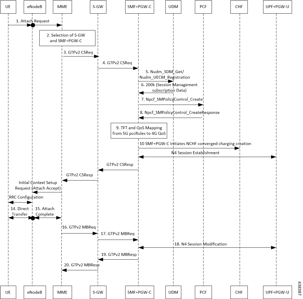
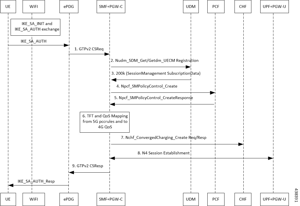
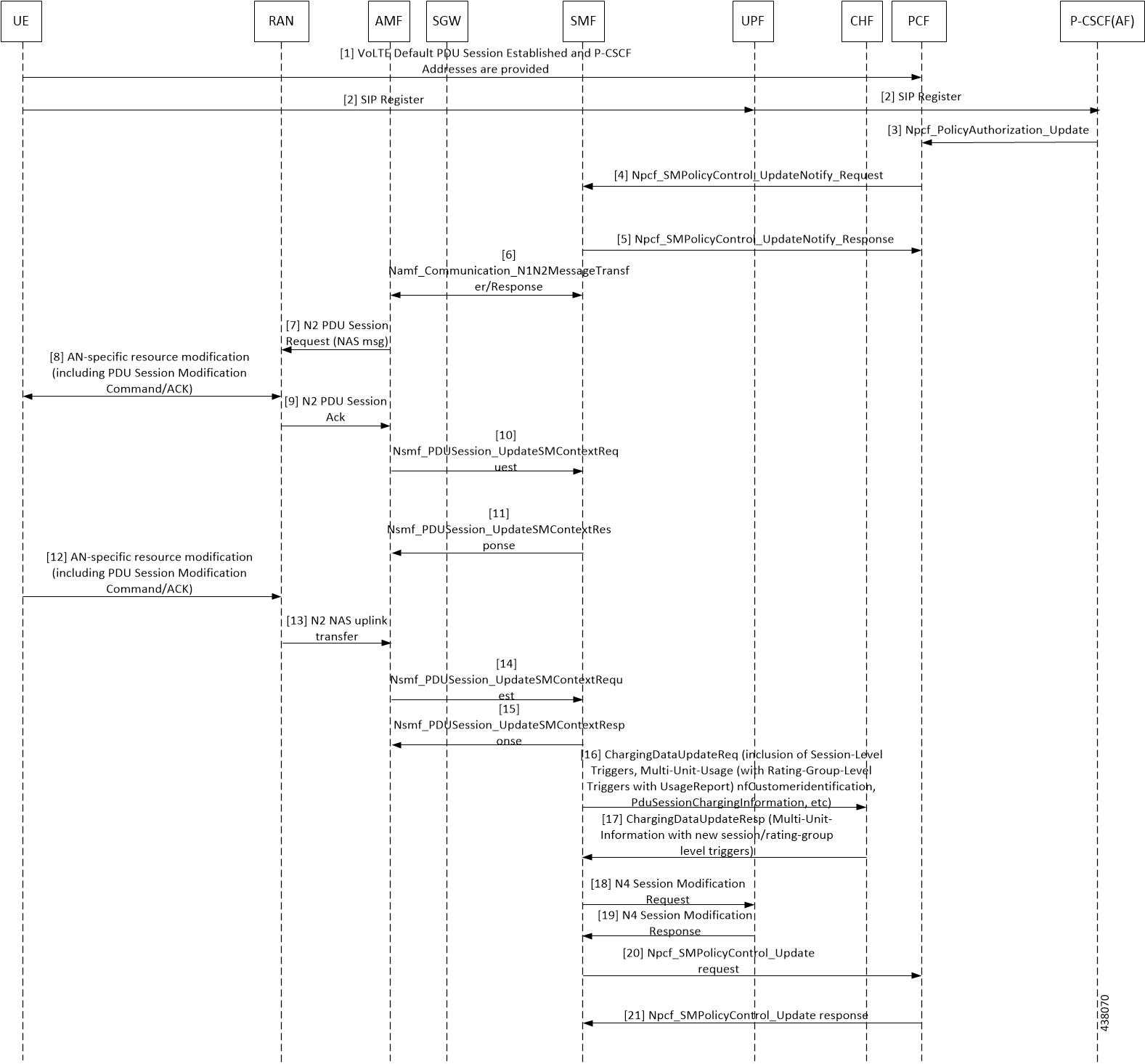
The SMF performs the PDU session establishment procedure as defined in 3GPP TS 23.502.

2

The UE initiates SIP Registration towards the called-party via UPF, P-CSCF through the backed IMS core network.

3

P-CSCF sends “Npcf_PolicyAuthorization_Update” to PCF to enforce policies, modify service information, gate control, modify subscription to SDF notification/deactivation, updating of traffic routing information, and so on (as defined in 3GPP TS 29.514). This service allows the NF consumer to subscribe and unsubscribe the notification of events (for example, change of Access Type, RAT type, or changes of the PLMN identifier).

4

The PCF sends Npcf_SMPolicyControl_UpdateNotify request to update and/or delete the PCC rule(s) PDU session-related policy context at the SMF and Policy Control Request Trigger information. This enforces PCC rules, policy control request triggers, SDF, and charging related information.

5

The SMF processes the received PCC rules and sends 200 OK message for a successful scenario. When the processing of any content fails, the SMF includes "400 Bad Request" in “Npcf_SMPolicyControl_UpdateNotify request” and sends it along with appropriate cause value as defined in 3GPP TS 29.512.

6

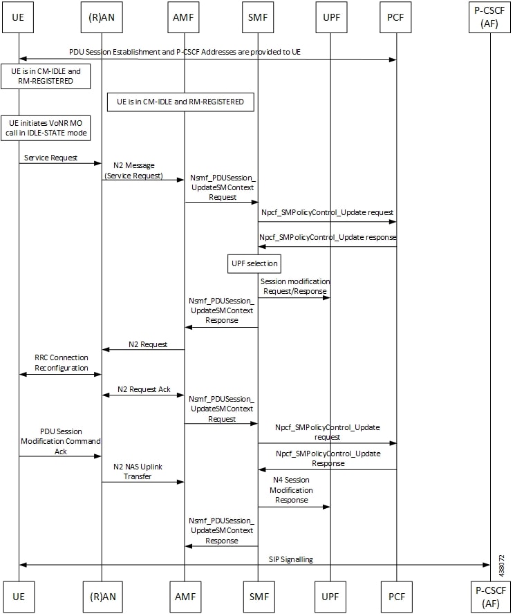
The SMF sends Namf_Communication_\nN1N2MessageTransfer/Response (PDU Session ID, QFIs, QoS Profile(s), Session-AMBR), N1 SM container (PDU Session Modification Command (PDU Session ID, QoS rule(s), QoS Flow level parameters if needed for the QoS Flow(s) associated with the QoS rule(s), QoS rule operation, and QoS Flow level QoS parameters operation, Session-AMBR))).

If the UE is in CM-IDLE state or Mobility handover (HO) state, see the procedure in VoNR MO Call Flow for UE in Idle Mode.

7

The AMF sends N2 PDU Session Request (N2 SM information received from SMF, NAS message (PDU Session ID, N1 SM container (PDU Session Modification Command))) message to the (R)AN.

8

The (R)AN issues AN specific signalling exchange with the UE that is related with the information received from SMF. For example, in an NG-RAN, an RRC Connection Reconfiguration takes place with the UE modifying the necessary (R)AN resources related to the PDU session.

9

The (R)AN acknowledges N2 PDU Session Request by sending a N2 PDU Session ACK (N2 SM information (List of accepted/rejected QFIs, AN Tunnel Info, PDU Session ID, Secondary RAT usage data), User Location Information) message to the AMF. In case of Dual Connectivity, if one or more QFIs were added to the PDU session, the primary RAN node assigns one or more of these QFIs to an NG-RAN node which was not involved in the PDU session earlier. In this case, the AN Tunnel Info includes a new N3 tunnel endpoint for QFIs assigned to the new NG-RAN node. Correspondingly, if one or more QFIs were removed from the PDU session, a (R)AN node may no longer be involved in the PDU session anymore, and the corresponding tunnel endpoint is removed from the AN Tunnel Info. The NG-RAN rejects QFIs if it cannot fulfill the User Plane Security Enforcement information for a corresponding QoS Profile, for example, due to the UE Integrity Protection Maximum Data Rate being exceeded.

10

The AMF forwards the N2 SM information and the User Location Information received from the (R)AN to the SMF via Nsmf_PDUSession_UpdateSMContext service operation.

If the (R)AN rejects QFIs, the SMF updates the QoS rules and QoS parameters if needed for the QoS flow(s) associated with the QoS rule(s) in the UE accordingly.

11

The SMF sends an Nsmf_PDUSession_UpdateSMContext Response. N2 SM information includes Secondary RAT Usage Data.

12

The UE acknowledges the PDU Session Modification Command by sending a NAS message (PDU Session ID, N1 SM container (PDU Session Modification Command ACK)) message.

13

The (R)AN forwards the NAS message to the AMF.

14

The AMF forwards the N1 SM container (PDU Session Modification Command ACK) and User Location Information received from the (R)AN to the SMF via Nsmf_PDUSession_UpdateSMContext service operation.

15

The SMF sends an Nsmf_PDUSession_UpdateSMContext Response.

If the SMF-initiated modification is to delete QoS Flows (for example, triggered by PCF) which do not include QoS Flow associated with the default QoS rule and the SMF does not receive response from the UE, the SMF marks that the status of those QoS Flows is to be synchronized with the UE.

16

SMF sends ChargingDataUpdateReq by including Multi-Unit-Usage with Rating-Group-Id that are received as part of Charging_Description of Sm_PolicyControl_UpdateNotify_Request to install PCC Rules.

17

CHF provides ChargingDataUpdtaeResp with Multi-Unit-Information for received Rating-Group values in requested message. CHF also provides parameter changes for Session-Level and Rating-Group values.

18

The SMF updates N4 session of the UPF(s) that are involved in the PDU Session Modification by sending N4 Session Modification Request (N4 Session ID) message to the PCF. For a PDU Session of Ethernet PDU Session Type, the SMF notifies the PCF to add or remove Ethernet Packet Filter Set(s) and forwarding rule(s).

The UPFs that are impacted in the PDU Session Modification procedure depend on the modified QoS parameters and the deployment. For example, in case of the session AMBR of a PDU Session with UL flow classifier (CL) changes, only the UL CL is involved.

19

The PCF sends an N4 session modification response message containing any information that the PCF has to provide to the SMF in response to the control information received.

20

For PCF-initiated policy modification case, the SMF notifies the PCF whether the PCC decision could be enforced or not by performing an SMF-initiated SM Policy Association Modification procedure as defined in 3GPP TS 23.502, section 4.16.5.1. The SMF notifies any entity that has subscribed to User Location Information related with PDU Session change.

21

The PCF sends an Npcf_SMPolicyControl_Update response with updated policy information about the PDU session.

VoNR MT Call Handling Procedure

This section describes the VoNR MT call handling procedure.

Figure 10. VoNR MT Call Handling Flow

The VoNR MT call handling procedure remains the same as the VoNR MO call handling procedure except for the SIP Registration Request initiated from UE to P-CSCF(AF) through the UPF.

VoNR MO Call Flow for UE in Idle Mode

This section describes the VoNR MO call handling procedure when the UE is in idle mode.

Figure 11. VoNR MO Call Handling Flow for UE in Idle Mode

Step

Description

1

The SMF performs the PDU session establishment procedure as defined in 3GPP TS 23.502 and fetches the P-CSCF addresses for sending it to the UE. The SMF programs UPF with Paging Policy Differentiation (PPD) for the respective PDU session as part of N4 interface by provisioning flows, and traffic detection information for every PDR.

2

The UE maintains its state in CM-IDLE and RM-REGISTERED.

3

The UPF maintains the UE in CM-IDLE and RM-REGISTERED state.

4

The UE initiates the VoNR call in CM-IDLE state.

5

The UE performs Service-Request procedures as defined in 3GPP TS 23.502.

6

The RAN sends N2 message (service request) to the AMF.

7

The AMF sends Nsmf_PDUSession_UpdateSMContext Request (PDU Session ID(s), Operation Type, UE Location information, Access Type, RAT Type, UE presence in LADN service area, Indication of Access Type can be changed) to the SMF.

8

If the AMF notifies the SMF that the access type of the PDU session can be changed, and if the PCC is deployed, the SMF performs an SMF-initiated SM Policy Association Modification procedure as defined in 3GPP TS 23.502, Section 4.16.5.1.

9

The PCF provides the updated PCC Rule(s) to the SMF.

10

The SMF initiates an N4 Session Modification request to the UPF. The SMF provides (R)AN Tunnel Info and the corresponding forwarding rules to the UPF. The UPF provides an N4 Session Modification Response to the SMF.

11

The SMF sends Nsmf_PDUSession_UpdateSMContext Response (N2 SM information (PDU Session ID, QFI(s), QoS profile(s), CN N3 Tunnel Info, S-NSSAI, User Plane Security Enforcement, UE Integrity Protection Maximum Data Rate), N1 SM Container, Cause) to the AMF. The SMF sends N1 SM Container and/or N2 SM Information to the AMF when applicable.

12

The AMF sends N2 Request (N2 SM information received from SMF, security context, Mobility Restriction List, Subscribed UE-AMBR, MM NAS Service Accept, list of recommended cells, TAs, NG-RAN node identifiers, UE Radio Capability, Core Network Assistance Information, Tracing Requirements) to the (R)AN.

13

The NG-RAN performs RRC Connection Reconfiguration with the UE depending on the QoS Information for all the QoS Flows of the PDU sessions whose UP connections are activated, and Data Radio Bearers.

14

The (R)AN sends N2 Request Acknowledgement message (N2 SM information (AN Tunnel Info, List of accepted QoS Flows for the PDU Sessions whose UP connections are activated, List of rejected QoS Flows for the PDU Sessions whose UP connections are activated), PDU Session ID) to the AMF.

The N2 Request ACK message includes N2 SM information, for example, AN Tunnel Info. NG-RAN responds N2 SM information with separate N2 message (for example, N2 tunnel setup response) if the AMF sends separate N2 message.

15

The AMF sends Nsmf_PDUSession_UpdateSMContext Request (N2 SM information, RAT Type, Access Type) per PDU Session to the SMF. The AMF determines Access Type and RAT Type based on the Global RAN Node ID associated with the N2 interface. If the AMF received N2 SM information (one or multiple), then the AMF forwards the N2 SM information to the relevant SMF per PDU Session ID. If the UE Time Zone has changed compared to the last reported UE Time Zone, then the AMF includes the UE Time Zone IE in this message.

16

The SMF notifies the PCF whether the PCC decision could be enforced or not by performing an SMF-initiated SM Policy Association Modification procedure as defined in 3GPP TS 23.502, Section 4.16.5.1. The SMF notifies any entity that has subscribed to User Location Information related with PDU Session change.

17

The PCF sends an Npcf_SMPolicyControl_Update response with updated policy information about the PDU session.

18

The SMF updates N4 session of the UPF(s) that are involved in the PDU session modification by sending N4 Session Modification Request (N4 Session ID) message to the UPF. For a PDU session of Ethernet PDU Session Type, the SMF notifies the UPF to add or remove Ethernet Packet Filter Set(s) and forwarding rule(s).

The UPFs that are impacted in the PDU Session Modification procedure depend on the modified QoS parameters and the deployment. For example, in case of the session AMBR of a PDU session with UL CL changes, only the UL CL is involved.

The UPF sends an N4 session modification response message containing any information that the UPF has to provide to the SMF in response to the control information received.

19

The SMF sends a Nsmf_PDUSession_UpdateSMContext Response. The N2 SM information includes Secondary RAT Usage Data.

VoNR MT Call Flow for UE in Idle Mode

This section describes the VoNR MT call handling procedure when the UE is in idle mode.

Figure 12. VoNR MT Call Flow for UE in Idle Mode

The VoNR MT call flow remains the same as the VoNR MO call flow for service request when the UE is in CM-IDLE state except the following:

  • The SIP-INVITE received by P-CSCF

  • The PCC rule enforcements triggered from PCF towards SMF.


Note


The PCC rules, QoS, PDR, and traffic detection rule enforcements remain the same as the VoNR MT Call Handling procedure as defined in VoNR MT Call Handling Procedure VoNR MT Call Handling Procedure.


When the AMF receives Namf_Communication_N1N2MessageTransfer Request (N2 SM information (PDU Session ID, QFI(s), QoS Profile(s), Session-AMBR), N1 SM container (PDU Session Modification Command (PDU Session ID, QoS rule(s), QoS Flow level parameters if needed for the QoS Flow(s) associated with the QoS rule(s), QoS rule operation, and QoS Flow level parameters operation, Session-AMBR))) when the UE is in CM-IDLE state. If the UE is in CM-IDLE state and an Asynchronous type communication (ATC) is activated, the AMF updates and stores the UE context based on the Namf_Communication_N1N2MessageTransfer.

The AMF performs paging operations to the UE, and the UE triggers service request procedure. Once the paging is established, the AMF decides QoS Flows, QoS rules, and Session-AMBR that need to be accepted, which are received in Namf_Communication_N1N2MessageTransfer Request and the AMF performs Nsmf_PDUSession_UpdateSMContext operation with SMF to notify on accepting the QoS Flows, QoS rules, session-AMBR, and so on.

VoNR Paging Policy Differentiation

Feature Description

The SMF supports Paging Policy Differentiation feature by providing a configuration at PLMN, DNN, and 5QI level for data and IMS DNN sessions of the UE. The SMF provides Paging Policy Indicator based on UPF data. The SMF also supports QoS flow (PPI, ARP, and 5QI) towards the AMF over N11 interface.

Call Flows

This section describes the call flows associated with this feature.

VoNR Paging Policy Differentiation Procedure

This section describes the VoNR Paging Policy Differentiation procedure.

Figure 13. VoNR Paging Policy Differentiation Call Flow
Table 13. VoNR Paging Policy Differentiation Call Flow Description

Step

Description

1

The SMF enables Paging Policy Differentiation (PPD) under DNN profile based on DNN, 5QI, and PLMN.

2

The SMF performs the PDU session establishment procedure as defined in 3GPP TS 23.502 and fetches the P-CSCF addresses for sending it to the UE. The SMF programs UPF with PPD for the respective PDU session as part of N4 interface by provisioning flows, and traffic detection information for every PDR.

3

The UPF detects if any Downlink (DL) Packet is set with DSCP value (TOS in IPv4 / TC in IPv6) when PPD is enabled for the PDU session.

4

The UPF detects that there is no forwarding path as there is no N3 Tunnel for the DSP marked DL packets.

5

The UPF sends Data-Notification (QFI, DSCP in TOS (IPv4) / TC (IPv6) in packet header).

6

The UPF enables DL Data buffering based on the buffering configuration. The UPF sends Data Notification (N4 Session ID, Information to identify the QoS Flow for the DL data packet, DSCP) message to the SMF.

  1. On arrival of the first DL data packet for any QoS Flow, the UPF sends Data Notification message to the SMF, if the SMF has not previously notified the UPF (in which case the next steps are skipped).

  2. If the UPF receives DL data packets for another QoS Flow in the same PDU session, the UPF sends another Data Notification message to the SMF.

  3. If the Paging Policy Differentiation feature (as specified in 3GPP TS 23.501, section 5.4.3) is supported by the UPF and if the PDU Session type is IP, the UPF includes the DSCP in TOS (IPv4) / TC (IPv6) value from the IP header of the DL data packet and the information to identify the QoS Flow for the DL data packet.

  4. The SMF sends the Data Notification Acknowledgement message to the UPF.

  5. The UPF forwards the DL data packets towards the SMF on request. The SMF buffers the data packets.

7

The SMF determines the AMF and invokes the Namf_Communication_N1N2MessageTransfer to the AMF including the PDU Session ID based on N4 Session ID. The SMF, while waiting for the User Plane Connection to be activated, receives additional Data Notification message.

The SMF derives a different Paging Policy Indicator according to the additional Data Notification or the DSCP of the data packet. The SMF invokes a new Namf_Communication_N1N2MessageTransfer indicating the higher priority or different Paging Policy Indicator to the AMF.

When supporting Paging Policy Differentiation, the SMF determines the Paging Policy Indicator related to the downlink data that has been received from the UPF or triggered the Data Notification message, based on the DSCP as described in 3GPP TS 23.501, section 5.4.3. The SMF indicates the Paging Policy Indicator in the Namf_Communication_N1N2MessageTransfer.

8

The AMF sends Namf_Communication_N1N2MessageTransfer response to the SMF with a cause “Attempting to reach UE" if the UE is in CM_IDLE State. If the UE is in CM-CONNECTED state, then the AMF sends a Namf_Communication_N1N2MessageTransfer response to the SMF immediately with a cause "N1/N2 transfer success".

9

The SMF sends Failure Indication to the UPF on receiving a negative response from AMF.

10

The AMF initiates paging towards the UE through the (R)AN.

11

The AMF initiates NAS Notification towards the UE.

12

The AMF notifies the SMF by sending Namf_Communications_N1N2MessageTransfer Failure Notification to the Notification Target Address provided by the SMF if the UE does not respond to paging. The AMF is unaware of an ongoing Mobility Management (MM) procedure that prevents the UE from responding. The AMF receives an N14 Context Request message indicating that the UE performs Registration procedure with another AMF.

13

If the UE is in CM-IDLE state, upon receiving a paging request for a PDU session associated to 3GPP access, the UE initiates the UE Triggered Service Request procedure as defined in 3GPP TS 23.502, section 4.2.3.2.

Configuring the VoNR Paging Profile Differentiation

This section describes how to configure VoNR Paging Profile Differentiation feature.

Configuring VoNR Paging Profile Differentiation feature involves the following steps:

  1. Creating PPD Profile

  2. Configuring PPD Profile Parameters

  3. Enabling PPD in DNN Profile Configuration

Creating PPD Profile

Use the following configuration to create an instance of PPD profile:

config 
   profile ppd ppd_profile_name 
   end 

NOTES:

  • ppd ppd_profile_name : Specifies the PPD profile. This command creates a PPD profile and provides access to the PPD Profile Configuration mode. For details on the commands supported in this mode, see the Ultra Cloud Core 5G Session Management Function, CLI Command Reference Guide. The value of ppd_profile_name must be an alphanumeric string.

Configuring PPD Profile Parameters

Use the following configuration to define the PPD profile parameters:

config 
   profile ppd ppd_profile_name 
      5qi 5qi_value 
      dscp dscp_value { ppi ppi_value } 
      end 

NOTES:

  • 5qi : Specifies the list of 5QI Priority Level. 5qi_value must be an integer in the range of 0-127. To list the different priority levels, use comma and hyphen as needed. For example, 5QI 3,10-15,65.

  • dscp dscp_value : Specifies the DSCP value. dscp_value must be an integer in the range of 0-63.

  • ppi ppi_value: Specifies the paging policy indicator value. ppi_value must be an integer in the range of 0-7.

Enabling PPD in DNN Profile Configuration

Use the following configuration to enable the PPD feature in the existing DNN profile configuration:

config 
   profile dnn dnn_profile_name 
      ppd-profile ppd_profile_name 
      end 

NOTES:

  • ppd-profile ppd_profile_name : This command defines the PPD profile to be associated with the DNN profile. pdd_profile_name must be the name of the configured PPD profile.

  • This command enables the PPD feature in the DNN profile based on the configured values of DNN, 5QI, and PLMN.

Verifying the Feature Configuration

Use the following show command to verify the feature configuration details.

show running-config

The following is an example of the output of this show command:


product smf# show running-config 
profile dnn dnntst1 
pcscf-profile pcscf1 
!