Redundancy Support

Feature Summary and Revision History

Summary Data

Table 1. Summary Data

Applicable Product or Functional Area

SMF

Applicable Platform

SMI

Feature Default Setting

  • Redundancy Support: Enabled - Configuration required to disable.

  • Traffic Monitoring on L2 VIP for Active Instance: Disabled - Configuration required to enable.

  • Geo Strengthening: Enabled - Configuration required to disable.

  • Minimize Session Loss During Application VIP switchover: Not Applicable.

Related Documentation

Not Applicable

Revision History

Table 2. Revision History

Revision Details

Release

Support added for the following sub-features:

  • Traffic Monitoring on L2 VIP for Active Instance.

  • Inter-site Redundancy.

  • GR Strengthening.

2023.03.0

Support added for Maintenance Mode.

2021.04.0

Geographic Redundancy (GR) support introduced.

2021.02.0

First introduced.

Pre-2020.02.0

Feature Description

This chapter provides an overview of the redundancy features, the architecture, and the configurations required to achieve the functionality in the failover scenario.

Types of Redundancies Supported

SMF supports following types of redundancies:

Redundancy Type

Description

Server

The solution is designed to sustain server failures and distribute the workload to another server in the cluster.

In this scenario, most of the essential and service critical pods are running in Active and Standby modes, and they reside on a different server to cause minimum impact in the event of a hardware failure.

Rack

In this scenario, the Kubernetes cluster is mirrored in the same Data Center, but on different racks.

In case of multiple server failures, software failures, or an adjacent routing layer issue, the sessions are switched to other racks. This way, it is assured to achieve the same level of service from the new rack.

Site

In this scenario, the Kubernetes cluster is mirrored in different geographical data centers.

In case of a whole data center is downtime, the sessions are switched to the other rack in a different data center. Through this, it is assured to achieve the same level of service from the new rack.

High Availability Support

Table 3. Feature History

Feature Name

Release Information

Description

Minimizing Session Loss During Application VIP switchover

2023.04

The High Availability redundancy support is enhanced in SMF in a way that when the gRPC IPC stream breaks, the App-Infra library re-tries immediately and the IPC connection is re-established between gRPC endpoints within milliseconds.

Feature Description

The SMF is built on the Kubernetes cluster strategy so that it inherits the high availability aspects of K8 cluster deployments. The SMF uses the construct that includes the components such as pods and services.

Each pod has at least 2 instances to ensure high availability against

  • Pod instance restart or failure

  • Pod lost due to node restart or failure

For details on the pods and services, see the Pods and Services Reference chapter in this guide.

High Availability of Node Manager

The SMF supports IPAM redundancy and load balancing for each UPF. The IPAM running in the Node Manager microservice has two IPAM instances that are associated to each UPF. When one IPAM instance is inactive, the other IPAM instance manages the address allocation requests for the UPF.

For more information on node manager redundancy, see the IPAM Redundancy Support Per UPF section in the IP Address Management chapter.

High Availability Inside Rack

High availability inside rack is an arrangement that handles server level redundancies. In this solution, in case of a single server failure, a few pods according to the design might get distributed in another available server. Meanwhile, other pods remain in pending state until the server comes back.

In this scenario, the critical pods that handle the external traffic run on Active-Stand-by pair on a different server. The redundancy support in the routing layer is provided by leaf and spine layers.

Figure 1. High Availability Layout

Architecture

This section describes the recommended layout of SMF pods and VMs.

SMF Pod and VM Deployment Layout

This section describes the deployment of SMF pods and its microservices.

The following figure shows the deployment model of six VMs in SMF.

Figure 2. VM Deployment Model

In this model, the pods are deployed on VM pairs. Two replicas are available for each protocol pod (for example, rest-ep, protocol-ep, and gtp-ep). One instance is deployed on each protocol VM.

Similarly, service pods and session pods are distributed on both the service and session VMs equally. Such a distribution is controlled by labelling the VMs as well as implementing the K8 affinity and anti-affinity rules during pod scheduling.

This model ensures that, during VM reboot scenarios, at least 50% of the replicas of each pod type are available to handle user signaling.

Graceful pod restart allows pod to complete ongoing processing within 30 seconds. Abrupt pod restart will affect ongoing transactions without impact to PDU sessions.

How It Works

This section provides information on how the resiliency and HA can be achieved.

The SMF enables inter-pod communication during the pod failure or restart.

During a graceful pod restart:

  • Ongoing processing is not impacted.

  • New messages are not sent to this pod through the Kubernetes service.

  • Messages with session affinity continue to be received by this pod.

  • Existing call flow expected to complete within 30 seconds.

After the pod restarts:

  • All Prometheus metrics of the pod are reset.

  • Internal pod diagnostics once passed, the pod's status is changed to ready.

  • The pod is ready to process the new messages.

When the SMF VM reboots or the VM is unavailable,

  • All pods on the VM are lost.

  • Pods on other available VM continue processing, thus providing high availability.

  • VIP if present is switched to the other available node.

  • It takes about 5 minutes of node unreachability for Kubernetes to detect the node as down.

  • Pods on the node are thereafter not discoverable through the Kubernetes service.

After the pod restarts, pods on the VM are scheduled one after another. This operation is similar to the pod restart.

During the VIP and VM reboot, virtual IP is associated with a single VM. UDP proxy binds to N4 VIP address for communication with UPF. UDP proxy binds to S5 VIP address for communication with cnSGW.

Reboot of VM with active VIP causes VIP to switch to other protocol VM. The active UDP proxy failure causes VIP to switch to the other protocol VM.

Before the Subscriber Microservices Infrastructure (SMI) handles the VIP monitoring and switchover, make sure that the appropriate VIP configuration is available in the SMI deployer. Also, check if the port is set to 28000 and the host priority is equal.

Configuring Pod-level Labelling and Replicas

The node label is configured on the SMI cluster deployer. For information on the configuration commandsin the chapter.

Configuration Example

The following is an example of VM labelling and replica configuration.

k8 label protocol-layer key smi.cisco.com/node-type value smf-proto
exit
k8 label service-layer key vm-type value smf-svc
exit
k8 label cdl-layer key smi.cisco.com/node-type value smf-cdl
exit
k8 label oam-layer key smi.cisco.com/node-type value oam
exit

endpoint pfcp
 replicas 1
 nodes    2
exit
endpoint service
 replicas 1
 nodes    2
exit
endpoint protocol
 replicas 1
 nodes    2
 vip-ip 209.165.201.28
exit
endpoint sbi
 replicas 1
 nodes    2

Configuration Verification

To verify the configuration, use the following show command:

show running-config instance instance-id instance_id endpoint 

The following is an example output of this show command.

[unknown] smf# show running-config instance instance-id 1 endpoint 
instance instance-id 1
 endpoint nodemgr
  replicas 1
  nodes    2
 exit
 endpoint gtp
  replicas 1
  vip-ip 209.165.202.149
 exit
 endpoint pfcp
  replicas                2
  enable-cpu-optimization true
  interface n4
   heartbeat
    interval               0
    retransmission-timeout 3
    max-retransmissions    5
   exit
  exit
 exit
 endpoint service
  replicas 2
 exit
 endpoint protocol
  replicas 1
  vip-ip 209.165.202.149
 exit
exit 

This command output displays the configurations related to multiple endpoints, such as endpoint names, pod replicas, nodes, and so on.

Traffic Monitoring on L2 VIP for Active Instance

Feature Description

SMF identifies active L2 VIPs on the protocol node that do not have any traffic. If case of an active L2 VIPs, there may not be any traffic due to various reasons, including network connectivity issues.

Upon detecting the no traffic scenario on active L2 VIPs, the SMF attempts to restart the pod or triggers the GR based on the CLI configuration action. It facilitates the restoration of traffic resulting in minimal loss of sessions.

This feature can be enabled or disabled using a CLI.

How It Works

  • The traffic monitoring on IPC L2 VIP happens periodically and is matched with configurable no-traffic-duration time.

  • If there is no traffic on the active IPC L2 VIP for the configured time duration, depending on the action configured either the GR trigger happens, so that other rack can handle the traffic, or the pod restarts, so that VIP switches to the other pod restoring traffic.

  • If a pod restart action is configured and even after the VIP switchover if traffic is not restored, the IPC connection monitoring feature will trigger the GR scenario if configured to minimize the impact.

  • Following checks are monitored periodically. If the checks fulfill the condition, the traffic is monitored:

    • CLI config no-traffic-duration should be greater than 10 seconds.

    • CLI config session-threshold should be greater than or equal to 1000. The default value is 1000.

    • Whether any of the GR Instance ID roles is PRIMARY.

    • Whether internal VIP is present on the protocol node.

    • If the session count is greater than or equal to the session threshold configured using the CLI, traffic monitoring is triggered. However, if the session count is less than 1000, traffic monitoring is stopped.

  • Single IPC endpoint handles traffic for both the GR Instance IDs in GR mode. Traffic monitoring on IPC endpoint will not be GR Instance ID specific. However, checks are done for both the GR Instance IDs.

Configuring HA and GR Scenarios

Use the following configuration to trigger HA (pod-restart) scenario or GR (trigger-switch-over) scenario:

config 
   monitor 
      active-instance-traffic {  no-traffic-duration no_traffic_duration session-threshold session_threshold action { pod-restart | trigger-switch-over  } } 

NOTES:

  • active-instance-traffic —Specify this keyword to enable or disable active traffic monitoring.

  • no-traffic-duration no_traffic_duration —Maximum allowed time in seconds of no traffic on active instance. The value range is 10-300. There is no default value set for this CLI. The value of no-traffic-duration should be less than the value of max-conn-downtime if set.

  • session-threshold session_threshold —Minimum session count required to start the active instance traffic monitoring. The value range is 10-10000000. The default value is 1000.

  • action { pod-restart | trigger-switch-over } —Action to take on condition fulfillment. The possible values for this command are pod-restart and trigger-switch-over . The default value is pod-restart .

Configuration Example

Following example shows the configuration of this feature:

smf(config)# monitor active-instance-traffic no-traffic-duration 15 session-threshold 1000 action pod-restart
Configuration Verification

Following show command displays the output for this feature:

smf# show running-config monitor active-instance-traffic
monitor active-instance-traffic no-traffic-duration 15 session-threshold 1000 action pod-restart

OAM Support

This section defines various statistics supported in this feature.

KPI

Following KPIs are supported as part of this feature:

Active Instance Traffic Monitor Services KPI

KPI Name

Description

Labels

active_instance_traffic_monitor_services

This statistic displays services which have registered for traffic monitoring.

interface_name

internal_vip_ip

Active Instance Traffic Monitor Status KPI

KPI Name

Description

Labels

Possible Values

active_instance_traffic_monitor_status

This statistic displays the status of active instance traffic monitoring.

interface_name

internal_vip_ip

0 – Not Monitoring

1 – Monitoring

Active Instance Traffic Monitor Reason KPI

KPI Name

Description

Labels

Possible Values

active_instance_traffic_monitor_reason

This statistic displays the reason if conditions do not meet for active instance traffic monitoring in the monitoring or not-monitoring state.

interface_name

internal_vip_ip

1 - GR Instance ID is not Primary

2 - Current session count is less than session threshold count

3 - Internal VIP not active

4 - Active Instance Traffic Monitor not configured

Active Instance Traffic Monitor Session Count KPI

KPI Name

Description

Labels

active_instance_traffic_monitor_session_count

This statistic displays the current session count.

interface_name

internal_vip_ip


Note


The count displayed will be from the affinity cache.


Active Instance Traffic Monitor Last Received Traffic KPI

KPI Name

Description

Labels

active_instance_traffic_monitor_last_recv_traffic

This statistic displays the last received traffic time in seconds.

interface_name

internal_vip_ip


Note


This statistic will be calculated only when all the conditions of the active instance traffic monitor are met.


Inter-Rack Redundancy Support

Inter-Rack redundancy support refers to the ability of a system or service to maintain its functionality and availability in the event of a failure or outage in one rack can be mitigated by moving the operations to another rack in the same geo location.

Feature Description

The SMF supports Inter-Rack redundancy in the active-active mode. The Inter-Rack redundancy is achieved through replication of sessions, configuration, and any other data required for seamless failover and failback of services to the remote rack.

How It Works

SMF (CNF) can be deployed in the same data center to provide service for a catastrophic failure localized to a rack hosting an SMF SMF cluster.

Each CNF instance service registers with NRF and S11/S5 for DNS entry for MME/SGW. Local HA redundancy allows instance to achieve rack level redundancy in addition to K8 cluster level failures within same data center or handle locally within same K8 cluster if failed containers are per Type-2 < n.

where, n is a value. For less than 50% of container failures, HA should handle the failures. For more than 50% of container failures, Inter-rack switchover is triggered.

Overview

In active-active mode,

  • The inter-rack deployment is transparent to the adjacent NFs.

  • The inter-rack deployment contains two instances of the CCG function, each instance manifest itself with a set of interface IPs.

  • Each instance support sets of sessions and continue to use the same IP for session consistency.

  • At a specific time period, one CCG instance can be primary only on one rack and standby on the other rack.

  • The set of interface IPs that are associated with the CCG instance, dynamically route to the primary rack of the instance.

SMF supports primary/standby redundancy in which data is replicated from the primary to standby instance. The primary instance provides services in normal operation. If the primary instance fails, the standby instance becomes the primary and takes over the operation. To achieve inter-rack redundancy, two primary/standby pairs can be set up where each rack is actively processing traffic and standby is acting as backup for the remote rack.

In an Active-Active inter-rack redundancy deployment, consider there are two racks: Rack-1 and Rack-2 located in the same data center. All the NFs are trying to reach instance-1 and instance-2.

Figure 3. Active-Active Inter-Rack Redundancy Deployment

For NFs, both the instances are active. But in real, instance-1 and instance-2 are divided across racks.

Rack-1 has instance-1 and instance-2. In a pre-trigger scenario, instance-1 is local and acts as Primary and instance-2 is in Standby mode.

Rack-2 also has instance-1 and instance-2. In a pre-trigger scenario, instance-2 is local and acts as Primary and instance-1 is in Standby mode.

In case, if Rack-1 goes down, the traffic moves to Rack-2. On Rack-2 both the instances, instance-1 and instance-2 acts as Primary.

Inter-Rack Redundancy Triggers

Inter-rack redundancy supports the following triggers:

  • CLI-based Switchover: Manual CLI commands are used to switch the roles and trigger inter-rack redundancy failover.

  • BFD Link Failover Detection: When both the BFD links between the connected rack and the leafs are down, inter-rack redundancy failover is triggered.

  • Local Rack POD Failure Detection: When threshold percentage of POD replica-sets failing is greater than the configured threshold value, the inter-rack redundancy failover is triggered.

  • Remote Rack POD Failure Detection: When the remote POD monitoring detects failure breaching threshold percentage, the POD becomes self-primary for that instance.

  • Remote Rack Role Monitoring: When the remote role monitoring detects that the rack is in Standy_error state, it becomes self-primary.

  • Multi-Compute Failure: When two or more servers are powered down, it triggers inter-rack redundancy failover.

Rack NF Roles

The following is a list of applicable rack NF roles:


Note


  • The Cachepod/ETCD and the CDL Replication happen during all the roles mentioned in the following section.

  • If the inter-rack links are down or under periodic heartbeat fails, then these inter-rack redundancy triggers get suspended.


  • PRIMARY: In this role, the rack is in ready state and actively taking traffic for the given instance.

  • STANDBY: In this role, the rack is in standby mode, ready to take traffic, but not taking traffic for the given instance.

  • STANDBY_ERROR: In this role, the rack is in problem state, not active, and not ready to take traffic for the given instance.


    Note


    When the instance role is in STANDBY_ERROR, data replication gets halted. The command show georeplication-status consistently fails under this condition. However, once the instance role gets transitioned to STANDBY, data replication resumes automatically, and the command displays the result as pass.


  • FAILOVER_INIT: In this role, the rack has started to fail over and not in condition to take traffic. The buffer time is two seconds for the application to complete their activity.

For fresh installation, the rack boots-up with the following roles:

  • PRIMARY: In this role, the rack is in for the local instance (each rack has local instance-id configured to identify the local instance). It is recommended not to configure the pods for monitoring during fresh installation. Once the setup is ready, you can configure the pods for monitoring.

  • STANDBY: In this role, the rack is in for other instances.

For upgrades, the rack boots-up with the following roles:

  • STANDBY_ERROR: In this role, the rack is for all the instances as moving the traffic post upgrade needs manual intervention.

General Guidelines

Before configuring the inter-rack redundancy deployment, here are some general guidelines:

  • Both racks should be on the same software version.

  • Both racks should be configured with same configuration.

  • Loopback port of Instance 1 and Instance 2 should be different. Else, REST-EP POD would not come up due to K8 IP/Port conflict.

  • Respective interface on both the racks should be on the same VLAN. For example, N4 VLAN of Instance1 and Instance2 should be on the same VLAN. Else, there is a route conflict on Kernel while enforcing BGP policies.

  • Consult your Cisco Technical Representative to perform the following procedures to make sure proper roles are assigned.

    For more information, see Software Upgrade on GR Pairs.

  • Post failover, perform the failback manually after ensuring the rack is healthy. Autonomous failback is not supported.

    For more information, see Recovery Procedure.

  • Use non-bonded interface in BGP speaker PODs for BGP peering.

  • BGP peering per Proto node is supported with only two BGP routers/leafs. Considering two Proto nodes, there can be maximum of four BGP neighborships.

  • Use bonded interfaces for Service traffic.

  • Geo pod uses two VIPs:

    • Internal-VIP for Inter-POD communication (within the rack)

    • External-VIP for Inter-rack Geo pod communication. Configure only on Proto Nodes on L2 Subnet. This is used to communicate across the racks. This node has external connectivity to other rack.

  • Geo Internal IP to be reachable to all nodes within the rack.

  • Geo External IP:

  • CDL/Kafka VIPs: Configure on CDL Labeled Nodes on L2 Subnet.

  • Enable LI tapping on both the racks.

  • MDF server should be reachable from both the racks.

Instance Awareness

Instance awareness configuration in SMF helps to distinguish local rack instance and remote rack instance.

Configuring Inter-Rack Redundancy Instance

This configuration is needed to provide a inter-rack redundancy configuration for multiple rack. With instance ID, endpoint configurations should be configured for each rack.

Sample Configuration 1

The following is a sample configuration for endpoint VIP configuration under one instance:

config 
  instance instance-id gr_instanceId 
    endpoint endpoint_name 
        vip-ip vip_ip_address 
  exit 
exit 

Example:

config
instance instance-id 1
 endpoint sbi
  vip-ip 209.165.201.21
 exit
exit
Sample Configuration 2

The following is a sample configuration to provide information on system-id, cluster-id and slice-name under an instance:

config 
  instances instance instance_id 
   system-id system_id 
   cluster-id cluster_id 
   slice-name cdl_slice_name 
  exit 
exit 

Example:

config
 instances instance 1
  system-id smf
  cluster-id smf
  slice-name 1
 exit
exit

Note


It is recommended to have the same values for system-id, cluster-id in the instance, and app-name, cluster-name in deployment.


Configuring Endpoint Instance Awareness

Only two instances can be configured on each local and remote rack, and corresponding endpoints can be instantiated.

A local instance-id is the identity of the local rack irrespective of if the rack is redundant or not.

Local Instance ID Configuration

The local instance is configured using the local-instance command.

local-instance instance 1

Endpoint configuration must be under instance specified by each unique instance ID.

Endpoint Configuration Example

Following are a few configuration examples.


Note


In the following example, instance-id "1" is a local instance-id, and endpoints configured under it belong to the local rack.

Optionally, remote rack instance-id "2" can be configured for endpoints belonging to the inter-rack.


instance instance-id 1
 endpoint li
  replicas 1
  nodes    2
  vip-ip 209.165.201.6
  vip-ip 209.165.201.13
 exit
 endpoint gtp
  replicas 1
  nodes    2
  retransmission timeout 5 max-retry 4
  vip-ip 209.165.201.6
  vip-ip 209.165.201.4
  interface s5
   echo interval          60
   echo retransmission-timeout 5
   echo max-retransmissions 4
  exit
  interface s2b
   echo interval 60
   echo retransmission-timeout 5
   echo max-retransmissions 4
  exit
 exit
exit
instance instance-id 2
 endpoint li
  replicas 1
  nodes    2
  vip-ip 209.165.201.6
  vip-ip 209.165.201.13
 exit
exit
endpoint gtp
  replicas 1
  nodes    2
  retransmission timeout 5 max-retry 4
  vip-ip 209.165.201.6
  vip-ip 209.165.201.5
  interface s5
   echo interval 60
   echo retransmission-timeout 5
   echo max-retransmissions 4
  exit
  interface s2b
   echo interval 60
   echo retransmission-timeout 5
   echo max-retransmissions 4
  exit
 exit
exit

Configuring Profile SMF Instance Awareness

Add instance for PGW FQDN corresponding to local and remote instances.

Example

Following is a configuration example.


Note


In the following example, instance-id "1" is a local instance-id, and the SMF profile configured under it belongs to the local rack.

Optionally, remote rack instance-id "2" can be configured for FQDN belonging to the inter-rack.


profile smf smf1
locality LOC1
allowed-nssai [ slice1 ]
instances 1 fqdn cisco.com.apn.epc.mnc456.mcc123
instances 2 fqdn cisco.com.apn.epc.mnc567.mcc123

Dynamic Routing

Border Gateway Protocol (BGP) allows you to create loop-free inter-domain routing between autonomous systems (AS). An AS is a set of routers under a single technical administration. The routers can use an Exterior Gateway Protocol to route packets outside the AS. The Dynamic Routing by Using BGP feature enables you to configure the next-hop attribute of a BGP router with alternate local addresses to service IP addresses with priority and routes. The App-Infra BGP speaker pods enable dynamic routing of traffic by using BGP to advertise pod routes to the service VIP.

This feature supports the following functionality:

  • Dynamic routing by using BGP to advertise service IP addresses for the incoming traffic.

  • Learn route for outgoing traffic.

  • Handling a BGP pod failover.

  • Handling a protocol pod failover.

  • Statistics and KPIs for the BGP speakers.

  • Log messages for debugging the BGP speakers.

  • Enable or disable the BGP speaker pods.

  • New CLI commands to configure BGP.

Incoming Traffic

BGP uses TCP as the transport protocol, on port 179. Two BGP routers form a TCP connection between one another. These routers are peer routers. The peer routers exchange messages to open and confirm the connection parameters.

The BGP speaker publishes routing information of the protocol pod for incoming traffic in the active standby mode. Use the following image as an example to understand the dynamic routing functionality. There are two protocol pods, pod1 and pod2. Pod1 is active and pod2 is in the standby mode. The service IP address, 209.165.200.225 is configured on both the nodes, 209.165.200.226 and 209.165.200.227. pod1 is running on host 209.165.200.226 and pod2 on host 209.165.200.227. The host IP address exposes the pod services. BGP speaker publishes the route 209.165.200.225 through 209.165.200.226 and 209.165.200.227. It also publishes the preference values, 110 and 100 to determine the priority of pods.

Figure 4. Dynamic Routing for Incoming Traffic in the Active-standby Topology

For high availability, each cluster has two BGP speaker pods with Active-standby topology. Kernel route modification is done at host network level where the protocol pod runs.

MED Value

The Local Preference is used only for IGP neighbours, whereas the MED Attribute is used only for EGP neighbours. A lower MED value is the preferred choice for BGP.

Table 4. MED Value

Bonding Interface Active

VIP Present

MED Value

Local Preference

Yes

Yes

1210

2220

Yes

No

1220

2210

No

Yes

1215

2215

No

No

1225

2205

Bootstrap of BGP Speaker Pods

The following sequence of steps set up the BGP speaker pods:

  1. The BGP speaker pods use TCP as the transport protocol, on port 179. These pods use the AS number configured in the Ops Center CLI.

  2. Register the Topology manager.

  3. Select the Leader pod. The Active speaker pod is the default choice.

  4. Establish connection to all the BGP peers provided by the Ops Center CLI.

  5. Publish all existing routes from ETCD.

  6. Configure import policies for routing by using CLI configuration.

  7. Start gRPC stream server on both the speaker pods.

  8. Similar to the cache pod, two BGP speaker pods must run on each Namespace.

For more information on Dynamic Routing, see the Dynamic Routing by Using BGP chapter in the UCC 5G Session Management Function - Configuration and Administration Guide.

Configuring Dynamic Routing Using BGP

This section describes how to configure the dynamic routing using BGP.

Configuring AS and BGP Router IP Address

To configure the AS and IP address for the BGP router, use the following commands:

config 
   router bgp local_as_number 
   exit 
exit 

NOTES:

  • router bgp local_as_number —Specify the identification number for the AS for the BGP router.

    In a inter-rack redundancy deployment, you need to configure two Autonomous Systems (AS).

    • One AS for leaf and spine.

    • Second AS for both racks: Rack-1 and Rack-2.

Configuring BGP Service Listening IP Address

To configure the BGP service listening IP address, use the following commands:

config 
   router bgp local_as_number 
      interface interface_name 
   exit 
exit 

NOTES:

  • router bgp local_as_number —Specify the identification number for the AS for the BGP router.

  • interface interface_name —Specify the name of the interface.

Configuring BGP Neighbors

To configure the BGP neighbors, use the following commands:

config 
   router bgp local_as_number 
      interface interface_name 
      neighbor neighbor_ip_address remote-as as_number 
   exit 
exit 

NOTES:

  • router bgp local_as_number —Specify the identification number for the AS for the BGP router.

  • interface interface_name —Specify the name of the interface.

  • neighbor neighbor_ip_address —Specify the IP address of the neighbor BGP router.

  • remote-as as_number —Specify the identification number for the AS.

Configuring Bonding Interface

To configure the bonding interface related to the interfaces, use the following commands:

config 
   router bgp local_as_number 
      interface interface_name 
      bondingInterface interface_name 
   exit 
exit 

NOTES:

  • router bgp local_as_number —Specify the identification number for the AS for the BGP router.

  • interface interface_name —Specify the name of the interface.

  • bondingInterface interface_name —Specify the related bonding interface for an interface. If the bonding interface is active, then the BGP gives a higher preference to the interface-service by providing a lower MED value.

Configuring Learn Default Route

If the user configures specific routes on their system and they need to support all routes, then they must set the learnDefaultRoute as true.


Note


This configuration is optional.


To configure the Learn Default Route, use the following commands:

config 
   router bgp local_as_number 
      learnDefaultRoute true/false 
   exit 
exit 

NOTES:

  • router bgp local_as_number —Specify the identification number for the AS for the BGP router.

  • learnDefaultRoute true/false —Specify the option to enable or disable the learnDefaultRoute parameter. When set to true, BGP learns default route and adds it in the kernel space. By default, it is false.

Configuring BGP Port

To configure the Port number for a BGP service, use the following commands:

config 
   router bgp local_as_number 
      loopbackPort port_number 
   exit 
exit 

NOTES:

  • router bgp local_as_number —Specify the identification number for the AS for the BGP router.

  • loopbackPort port_number —Specify the port number for the BGP service. The default value is 179.

Policy Addition

The BGP speaker pods learns many route information from its neighbors. However, only a few of them are used for supporting the outgoing traffic. This is required for egress traffic handling only, when SMF is sending information outside to AMF/PCF. Routes are filtered by configuring import policies on the BGP speakers and is used to send learned routes to the protocol pods.

A sample CLI code for policy addition and the corresponding descriptions for the parameters are shown below.

$bgp policy <policy_Name> ip-prefix 209.165.200.225 subnet 16 masklength-range 21..24 as-path-set “^65100”
Table 5. Import Policies Parameters
Element Description Example Optional
as-path-set AS path value “^65100” Yes
ip-prefix Prefix value “209.165.200.225/16” Yes
masklength-range Range of length “21..24” Yes
interface Interface to set as source IP (default is VM IP) eth0 Yes
gateWay Change gateway of incoming route 209.165.201.30 Yes
modifySourceIp Modify source ip of incoming route

Default value is False.

true Yes
isStaticRoute Flag to add static IP address into kernel route

Default value is False.

true Yes

Configuring BGP Speaker

This configuration controls the number of BGP speaker pods in deployment. BGP speaker advertises service IP information for incoming traffic from both the racks.


Note


  • Use non-bonded interface in BGP speaker pods for BGP peering.

  • BGP peering per Proto node is supported with only two BGP routers/leafs. Considering two Proto nodes, there can be maximum of four BGP neighborships.


instance instance-id  instance_id endpoint bgpspeaker interface { bgp | bfd } internal base-port start base_port_number 
config 
instance instance-id instance_id 
 endpoint bgpspeaker 
   replicas replica_id 
   nodes node_id 
   interface bgp 
     internal base-port start base_port_number  
   exit 
   interface bfd 
     internal base-port start base_port_number 
  exit 
exit 

NOTES:

  • instance instance-id instance_id —Specify the GR instance ID.

  • base_port_number —Specify the port range only if logical NF is configured. This range depends on your deployment.

Example

The following is a configuration example:

instance instance-id 1
endpoint bgpspeaker
   replicas 1
   nodes    2
   interface bgp
     internal base-port start {24000}
   exit
   interface bfd
     internal base-port start {25000}
 exit

IPAM

This section describes IP Address Management (IPAM) at the rack level.

Figure 5. IPAM

During UPF registration, active IPAM instance reserves four address-ranges per UPF per DNN.

  • Range-1: Active cluster, nodemgr-1

  • Range-2: Active cluster, nodemgr-2

  • Range-3: Standby cluster, nodemgr-1

  • Range-4: Standby cluster, nodemgr-2

During normal operation, Rack-1 handles UPF-register/release, address-allocate/release for subscribers coming up in GR-instance-1.

If Rack-2 goes down, Rack-1 gets role-change trigger for GR-Instance-2.

  • IPAM in Rack-1, restores the content of GR-Instance-2 from local-cache-pod (which was already synced)

  • IPAM in Rack-1 handles UPF-Register/Release and address-allocate/release for subscribers coming up with GR-Instance-2 using the restored content in addition to handling GR-Instance-1.

Each IPAM pool is associated to a GR-Instance, with the following:

  • Pool name is unique across all the instances.

  • Address-ranges are unique within VRF and across all the instances.

The same pool configuration must be configured in both the active and standby SMF clusters of a particular instance.

During address-allocation, active instance assign free-IP from reserved address-range for the UPF.

Incase new address-ranges is not available, change ownership of standby’s address-range to current active instance and continue assigning address-ranges from it.

Configuring IPAM

The following section provides IPAM configuraton examples.

SMF-1 Example

The following is a configuration example for SMF-1:

ipam
 instance 1
  address-pool pool-1
  vrf-name ISP
   tags
   dnn dnn-1
  exit
  ipv4
    address-range 209.165.201.1 209.165.201.31
 exit
instance 2
 address-pool pool-2
  vrf-name ISP
  tags
   dnn dnn-2
  exit
  ipv4
    address-range 209.165.202.129 209.165.202.159
 exit
exit
SMF-2 Example

The following is a configuration example for SMF-2:

ipam
 instance 1
 address-pool pool-1
  vrf-name ISP
  tags
   dnn dnn-1
  exit
  ipv4
    address-range 209.165.201.1 209.165.201.31
 exit
 instance 2
 address-pool pool-2
  vrf-name ISP
   tags
   dnn dnn-2
  exit
  ipv4
    address-range 209.165.202.129 209.165.202.159
 exit
exit

Geo Replication

The Geo-replication is used in inter-rack communication and for POD or VIP or BFD monitoring within the rack. The Geographic Redundancy comprises with the following:

  • Two instances of Geo pods are running for each rack.

  • Two Geo pods functions in Active-Standby mode.

  • Each Geo pod instance is spawned on a different Proto node or VM.

  • Geo pod running on the Proto node or VM having VIP is Active Geo pod.

  • In the event of Active Geo pod restart, VIPs get switched to other Proto node or VM and Standby Geo pod running on the other Proto node/VM becomes active.

  • Geo pod uses host networking mode (similar to UDP-Proxy).

  • Geo pod uses two VIPs:

    • Internal: VIP for Inter-POD communication (within the rack)

    • External: VIP for Inter-rack Geo pod communication

      It configures only on Proto Nodes on the L2 Subnet. It's used to communicate across the racks. This node has external connectivity to other Rack.

  • Logical-NF-InstanceID must be configured same for both SMFs in GR-Pair.

  • For KeepAliveD monitoring:

    • Geo pod uses base port as: 15000+(Logical-NF-InstanceID * 32) + 4

      Geo pod base port must be different than BGP speaker pod port.

      • The default port (without logical SMF) as: 15004

      • For Logical SMF configured with logical-nf-instance-id as 1, and then the port as: 15036

    • UDP-Proxy pod uses base port as: 28000+Logical-NF-InstanceID.

      • The default port (without logical SMF) as: 28000

      • For Logical SMF configured with logical-nf-instance-id as 1, and then the port as: 28001

    • BGPSpeaker-pod uses default base port as: 20000+(Logical-NF-InstanceID * 32)+4.

      • The default port (without logical SMF) as: 20004

      • For logically SMF configured with logical-nf-instance-id as 1, and then the port as: 20036


Note


Only ETCD and cache pod data gets replicated to the standby rack.


Configuring ETCD/Cachepod Replication

Endpoints must be configured under an instance. Two Geo-Redundancy pods are needed on each rack. You should also configure VIP for internal and external Geo interface for ETCD/CachePod replication.

instance instance-id  instance_id endpoint geo interface { geo-internal | geo-external } vip-ip { vip_ip_address } vip-port { vip_port_number }
 
config 
instance instance-id instance_id 
 endpoint geo 
  replicas replica_id 
  nodes node_id 
  internal base-port start base_port_number 
  interface geo-internal 
   vip-ip vip_ip_address vip-port vip_port_number 
  exit 
  interface geo-external 
   vip-ip vip_ip_address vip-port vip_port_number 
  exit 
exit 
exit 

NOTES:

  • instance instance-id instance_id —Specify GR instance ID. One instance ID for local rack and other for another rack.

  • vip-ip vip_ip_address —Specify VIP IP address for Internal/External Geo interface.

  • vip-port vip_port_number —Specify VIP port number.

  • internal base-port start base_port_number —Specify port range only if logical NF is configured.

Example

The following is a configuration example:

instance instance-id 1
endpoint geo
  replicas 1
  nodes 2
  internal base-port start 25000
  interface geo-internal
   vip-ip 209.165.201.8 vip-port 7001
  exit
  interface geo-external
   vip-ip 209.165.201.8 vip-port 7002
  exit
exit

Geo Monitoring

This section describes Geo monitoring.

Pod Monitoring

To configure pod monitoring and failover thresholds in the inter-rack setup, use the following sample configuration. The geo pod monitors the configured pod name.

config 
 geomonitor 
  podmonitor pods pod_name 
   retryCount value 
   retryInterval interval_value 
   retryFailOverInterval failover_interval 
   failedReplicaPercent percent_value 
  exit 
 exit 

NOTES:

  • pods pod_name —Specify the name of the pod to be monitored. For example, Cache-pod, rest-ep, and so on.

  • retryCount value —Specify the retry counter value to retry if pod fails to ping after which pod is marked as down. It should be an integer in the range of 1-10.

  • retryInterval interval_value —Specify the retry interval in milliseconds if the pod successfully pings. It should be an integer in the range of 200-10000.

  • retryFailOverInterval failover_interval —Specify the retry interval in milliseconds if the pod fails to ping. It should be an integer in the range of 200-10000.

  • failedReplicaPercent percent_value —Specify the percent value of failed replica after which the inter-rack redundancy failover is triggered. It should be an integer in the range of 10-100.

Configuration Example

The following is an example configuration.

geomonitor podmonitor pods cache-pod
 retryCount 3
 retryInterval 5
 retryFailOverInterval 1
 failedReplicaPercent 40
exit

Remote Cluster Monitoring

Remote cluster monitoring auto corrects roles (it becomes self-primary, when the remote rack is in STANDBY_ERROR state) for uninterrupted traffic flow of traffic. However, this auto role correction gets done only for specific roles.

To configure this feature, use the following sample configuration:

config 
    geomonitor 
        remoteclustermonitor 
            retryCount value 
            retryInterval interval_value 
            end 

NOTES:

  • retryCount value —Specify the retry count before making the current rack PRIMARY. It should be an integer in the range of 1-10. The default value is 3.

  • retryInterval interval_value —Specify the retry interval in the count of milliseconds, after which the remote rack status gets fetched. It should be an integer in the range of 200-50000. The default value is 3000.

Configuration Example

The following is an example configuration

geomonitor remoteclustermonitor
retryCount 3
retryInterval 3000

Traffic Monitoring

The following command is used to monitor the traffic.

config 
 geomonitor 
  trafficMonitor 
   thresholdCount value 
   thresholdInterval interval_value 
  exit 
 exit 

NOTES:

  • thresholdCount value —It specifies the number of calls received for standby instance. It should be an integer in the range of 0-10000. Default value is 0. Both UDP-proxy and REST-EP must be considered for the counter value.

  • thresholdInterval interval_value —It specifies the maximum duration to hit the threshold count value in ms. It should be an integer in the range of 100-10000. Default value is 3000.

Configuration Example

The following is an example configuration

geomonitor trafficmonitor
thresholdCount 3
thresholdInterval 3000

Geo Redundancy Strengthening

The geo redundancy strengthening activity addresses multiple issues stemming from different scenarios such as the following:

  • Hardware failure

  • Network failure

  • Process failure

  • Abnormal conditions

  • Code walkthroughs

These failed scenarios impact the functionality of the geo-replication pod, causing the system malfunction. To address these issues, it is necessary to strengthen various areas of the geo-replication pod.

How It Works

The following areas of the enhanced geo replication pod are part of the geo redundancy strengthening feature:

  • The system makes GRPC replication and admin stream available when it becomes healthy.

  • The system ensures that both instances have the correct role in all scenarios.

  • The system maintains data replication between the geo replication pod of rack-1 and rack-2 in sync.

  • The system verifies that checksum and checkpoint data is always correct on both racks to ensure data integrity.

  • The system provides a mechanism for users to sync replication data, when it becomes out of sync, and requires manual intervention.

    To know more about the command, see the Geo Replication Pull Data section.

  • The system ensures that Geo VIP movement between geo replication pods does not impact functionality.

  • The system takes measures to prevent failures of dependent processes from affecting its functionality for users.

Limitations

Some of the known limitations of this feature are as follows:

  • Replication Data Loss: It can occur when a switchover occurs because both cache pods are down on the partner rack.

OAM Support

This section describes operations, administration, and maintenance support for this feature.

KPI Support

The following set of statistics supports the geo redundancy strengthening and securing feature:

  1. KPI Name: geo_replication_finalpull_total

    The following table lists geo_replication_finalpull_total KPI details.

    Description

    Functionality

    Label Names

    Possible Values

    This KPI displays the total number of geo replications present in the final pull of the feature messages.

    geo_replication_finalpull_total, it is the functionality output.

    MessageType

    It is a request or a response message type.

    TotalTimeTaken

    It is the total time taken to process the request.

    GRInstanceNumber

    It is the GR Instance ID in number from the list of the following:

    • 1

    • 2

    • Instance.1

    • Instance.2

BFD Monitoring

Bidirectional Forwarding Detection (BFD) protocol is used for Faster Network Failure Detection along with BGP. Whenever connectivity between BGP peering fails with cluster (NF), failover is triggered to minimize traffic failure impact.

config 
  router bgp as 
    bfd interval interval min_rx min_rx multiplier multiplier 
    loopbackPort loopbackPort loopbackBFDPort loopbackBFDPort 
  interface interface_id  (BGP on non-bonded interface <-- loopbackEth)
    bondingInterface bondingInterface  (leaf6-nic)
    bondingInterface bondingInterface  (leaf6-nic)
    neighbor neighbor_ip_address remote-as remote_as fail-over fail_over_type 
  exit 
  interface interface_id  (BGP on non-bonded interface <-- loopbackEth)
    bondingInterface bondingInterface  (leaf7-nic)
    bondingInterface bondingInterface  (leaf7-nic)
    neighbor bondingInterface remote-as remote_as fail-over fail_over_type 
  exit 
  policy-name policy_name  
   as-path-set as_path_set 
   gateWay gateWay_address 
   interface interface_id_source 
   ip-prefix ip_prefix_value 
   isStaticRoute false | true 
   mask-range mask_range 
   modifySourceIp false | true 
  exit 
exit 

NOTES:

  • bgp as —Specify the Autonomous System (AS) path set.

  • bfd —Specify BFD configuration.

    • interval interval —Specify BFD interval in milliseconds.

    • min_rx min_rx —Specify BFD minimum RX in milliseconds.

    • multiplier multiplier —Specify BFD interval multiplier.

  • interface interface_id —Specify BGP local interface.

    • bondingInterface bondingInterface —Specify linked bonding interface.

    • neighbor neighbor_ip_address —Specify IP address of neighbor.

      • fail-over fail_over_type —Specify failover type.

      • remote-as remote_as —Specify Autonomous System (AS) number of BGP neighbor.

  • learnDefaultRoute —Learn default route and add it in kernel space

  • loopbackBFDPort loopbackBFDPort —Specify BFD local port.

  • loopbackPort loopbackPort —Specify BGP local port.

  • policy-name policy_name —Specify policy name.

    • as-path-set as_path_set —Specify Autonomous System (AS) path set.

    • gateWay gateWay_address —Specify gateway address.

    • interface interface_id_source —Specify interface to set as source IP.

    • ip-prefix ip_prefix_value —Specify IP prefix value.

    • isStaticRoute false | true —Specify whether to add static route in kernel space. Default value is false.

    • mask-range mask_range —Specify mask range.

    • modifySourceIp false | true —Modify source IP of the incoming route. Default value is false.

      true: This option is used for non-UDP related VIPs. Source IP of the given interface is used as Source IP while sending out packets from SMF.

      false: This option is used for all UDP related VIPs. VIP is used as Source IP while sending out packets from SMF.

Example

Following are configuration examples:

router bgp 65000
  bfd interval 250000 min_rx 250000 multiplier 3
  loopbackPort 179 loopbackBFDPort 3784
interface ens160 (BGP on non-bonded interface <-- loopbackEth)
  bondingInterface enp216s0f0 (leaf6-nic)
  bondingInterface enp216s0f1 (leaf6-nic)
  neighbor leaf6-ip remote-as 60000 fail-over bfd
exit
interface ens192 (BGP on non-bonded interface <-- loopbackEth)
  bondingInterface enp94s0f1 (leaf7-nic)
  bondingInterface enp94s0f0 (leaf7-nic)
  neighbor leaf7-ip remote-as 60000 fail-over bfd
exit
policy-name allow-all ip-prefix 209.165.201.30/0 mask-range 0...32
exit

BGP router configuration with BFD

show running-config router          
router bgp 65142
 learnDefaultRoute false
 bfd interval 250000 min_rx 250000 multiplier 3
 interface enp94s0f0.3921
  bondingInterface enp216s0f0
  bondingInterface enp94s0f0
  neighbor 209.165.201.24 remote-as 65141 fail-over bfd
 exit
 interface enp94s0f1.3922
  bondingInterface enp216s0f1
  bondingInterface enp94s0f1
  neighbor 209.165.202.24 remote-as 65141 fail-over bfd

Show BFD status of neighbor

show bfd-neigbor
status-details

----- bgpspeaker-pod-1----

Peer             Status

209.165.202.142  STATE_DOWN
----- bgpspeaker-pod-2----

Peer             Status

209.165.202.142  STATE_UP
policy-name allow-n11 ip-prefix 209.165.200.225/54 mask-range 25..32 interface bd1.n11.2271 modifySourceIp true isStaticRoute true gateWay 209.165.201.14

In the above example, modifySourceIp is set to true.

  • AMF subnet: 209.165.200.225/54

    N11 Svc Bonded Physical Interface: bd1.n11.2271 (IP address - 209.165.201.23)

    N11 Svc Bonded VxLAN Anycast GW: 209.165.201.14

    N11 VIP Address: 209.165.201.7

  • SMF Outbound Packet (will have source IP as 209.165.201.23)

    Inbound Packet to SMF (will have destination IP as 209.165.201.7)

policy-name allow-n4-1 ip-prefix 209.165.201.17/41 mask-range 24..32 interface bd2.n4.2274 gateWay 209.165.201.17

In the above example, modifySourceIp is set to false (default).

  • UPF N4 Interface IP: 209.165.201.17/41

    N4 Svc Bonded Physical Interface: bd2.n4.2274 (IP address - 209.165.201.23)

    N4 Svc Bonded VxLAN Anycast GW: 209.165.201.17

    N4 VIP Address: 209.165.201.14

  • SMF Outbound Packet (will have source IP as 209.165.201.14)

    Inbound Packet to SMF (will have destination IP as 209.165.201.14)

CDL GR Deployment

By default, CDL is deployed with two replicas for db-ep, 1 slot map (2 replicas per map), and 1 index map (2 replicas per map).


Note


It is recommended to configure the CDL container in YANG.


Prerequisites for CDL GR

Before deploying the CDL GR, user must configure the following:

  • CDL Session Database and define the base configuration.

  • Kafka for CDL.

  • Zookeeper for CDL.

CDL Instance Awareness and Replication

In CDL, along with existing GR related parameters, GR instance awareness must be enabled using a feature flag on all the racks. Also, the mapping of system-id to slice names should also be provided for this feature to work on all the racks.

The CDL is also equipped with Geo Replication (GR) failover notifications, which can notify the timer expiry of session data and bulk notifications to the currently active rack. The CDL uses Border Gateway Protocol (BGP) through App-Infra for the GR failover notifications.

The CDL subscribes to the key value on both the GR racks. The App-Infra sends notifications to the CDL when there is any change in these key values. A key value indicates the state of the CDL System ID or the GR instance. The GR instance is mapped to the CDL slices using the CDL system ID or the GR instance ID in the key.

The system ID is mandatory on both the racks. The GR instance ID in the NF configuration must match the CDL system ID.

CDL has instance-specific data slices. It also allows users to configure instance-specific slice information at the time of bringing up.

  • CDL notifies the data on expiry or upon bulk notification request from the active slices.

  • CDL determines the active instance based on the notification from app-infra memory-cache.

  • CDL slice is a partition within a CDL instance to store a different kind of data. In this case, NF stores a different instance of data.


Note


CDL slice name should match with the slice-name configured in GR.


Configuring CDL Instance Awareness

The following command is used to configure CDL instance awareness.

config 
cdl 
 datastore datastore_session_name 
   features 
     instance-aware-notification 
       enable [ true | false ] 
       system-id system_id 
        slice-names slice_names 
    end 

NOTES:

  • datastore datastore_session_name —Specify the datastore name.

  • enable [ true | false ] —Enables the GR instance state check for slices.

  • system-id system_id —Mapping of system ID to slice name.

  • slice-names slice_names —Specify the list of slice names associated with the system ID. CDL slice name should match with the slice-name configured in GR.

Example

The following is a configuration example:

cdl datastore session
 features instance-aware-notification enable true
 features instance-aware-notification system-id 1
  slice-names [ sgw1 smf1 ]
 exit
 features instance-aware-notification system-id 2
  slice-names [ sgw2 smf2 ]
 end
Configuring CDL Replication

This section describes CDL replication configuration.

  1. Configure Rack-1 CDL HA system without any Geo-HA-related configuration parameters.

    1. Set the System ID as 1 in the configuration.

    2. Set the slot map/replica and index map/replica and Kafka replica as per requirements.

    The following is a sample configuration:

    cdl system-id 1 
    cdl node-type session 
    cdl datastore session 
    endpoint replica replica_id 
      slot map 4 
      slot replica 2 
      index map 1 
      index replica 2 
    cdl kafka replica 2 
    
  1. Configure external IPs on Rack-1 for Rack-2 to Rack-1 communication.

    1. Enable geo-replication on Rack-1 and configure the remote Rack as 2 for Rack-1.

      cdl enable-geo-replication true
    2. Configure the external IP for CDL endpoint to be accessed by Rack-2.

      cdl datastore session endpoint external-ip site-1_external_ip
    3. Configure the external IP and port for all Kafka replicas.

      So, if two replicas (default) are configured for Kafka, user need to provide two different <ip>+<port> pairs.

      cdl kafka external-ip site-1_external_ip port1 cdl kafka external-ip site-1_external_ip port2 
  2. Add remote rack information on Rack-2.

    • Remote rack cdl-ep configuration on Rack-2:

      cdl remote-site 1 db-endpoint host site-1_cdl_ep_ip

      cdl remote-site 1 db-endpoint port site-1_cdl_ep_port

      (Port Example: 8882)

    • Remote rack Kafka configuration on Rack-2:

      cdl remote-site 1 kafka-server site-1_kafka1_ip site-1_kafka1_port

      cdl remote-site 1 kafka-server site-1_kafka2_ip site-1_kafka2_port

    • Direct the session datastore configuration to remote Rack-2 configuration:

      cdl datastore session geo-remote-site 1

    • (Optional) Configure the SSL certificates to establish a secure connection with remote rack on Rack-1. All the certificates are in multi-line raw text format. If the certificates are not valid, the server continues with non-secure connection.

      cdl ssl-config certs site-2_external_ip ssl-key <ssl_key>

      cdl ssl-config certs site-2_external_ip ssl-crt <ssl_crt>

  3. Commit GR configuration on Rack-2:

    • Commit the configuration and let the pods be deployed on Rack-2.

    • Verify all pods are in running state.

    • Once both the racks are deployed, verify that the mirror maker pods on both racks are running and in ready state.

Examples

HA:

cdl node-type db-ims

cdl datastore session
 endpoint replica 2
 index map    1
 index write-factor 1
 slot replica 2
 slot map     4
 slot write-factor 1
exit

k8 label cdl-layer key smi.cisco.com/node-type value smf-ims-session

Rack-1:

cdl system-id          1
cdl node-type          session
cdl enable-geo-replication true
cdl zookeeper replica 1

cdl remote-site 2
 db-endpoint host 209.165.201.21 >> Rack-2 external CDL IP
 db-endpoint port 8882
 kafka-server 209.165.201.21 10092 >> Rack-2 external CDL IP
 exit
exit

cdl label-config session
 endpoint key smi.cisco.com/node-type1
 endpoint value smf-cdl
 slot map 1
  key   smi.cisco.com/node-type1
  value smf-cdl
 exit
 index map 1
  key   smi.cisco.com/node-type1
  value smf-cdl
 exit
exit
cdl logging default-log-level debug

cdl datastore session
 label-config    session
 geo-remote-site [ 2 ]
 slice-names     [ 1 2 ]
 endpoint cpu-request 100
 endpoint replica 2
 endpoint external-ip 209.165.201.25 >> Rack-1 external CDL IP
 endpoint external-port 8882
 index cpu-request 100
 index replica 2
 index map   1
 slot cpu-request 100
 slot replica 2
 slot map    1
exit

cdl kafka replica 1
cdl kafka label-config key smi.cisco.com/node-type1
cdl kafka label-config value smf-cdl
cdl kafka external-ip 209.165.201.25 10092 >> Rack-1 external CDL IP

Rack-2:

cdl system-id          2
cdl node-type          session
cdl enable-geo-replication true
cdl zookeeper replica 1

cdl remote-site 1
 db-endpoint host 209.165.201.25 >> Rack-1 external CDL IP
 db-endpoint port 8882
 kafka-server 209.165.201.25 10092 >> Rack-1 external CDL IP
 exit
exit

cdl label-config session
 endpoint key smi.cisco.com/node-type12
 endpoint value smf-cdl
 slot map 1
  key   smi.cisco.com/node-type12
  value smf-cdl
 exit
 index map 1
  key   smi.cisco.com/node-type12
  value smf-cdl
 exit
exit

cdl datastore session
 label-config    session
 geo-remote-site [ 1 ]
 slice-names     [ 1 2 ]
 endpoint cpu-request 100
 endpoint replica 2
 endpoint external-ip 209.165.201.21 >> Rack-2 external CDL IP
 endpoint external-port 8882
 index cpu-request 100
 index replica 2
 index map   1
 slot cpu-request 100
 slot replica 2
 slot map    1
exit

cdl kafka replica 1
cdl kafka label-config key smi.cisco.com/node-type12
cdl kafka label-config value smf-cdl
cdl kafka external-ip 209.165.201.21 10092 >> Rack-2 external CDL IP

Lawful Intercept

The Lawful Intercept (LI) feature enables law enforcement agencies (LEAs) to intercept subscriber communications. The LI functionality provides the network operator the capability to intercept control and data messages of the targeted mobile users. To invoke this support, the LEA requests the network operator to start the interception of a particular mobile user. Legal approvals support this request.

  1. Lawful Intercept (LI) tap should be configured/enabled on all the racks. If LI configuration fails on one rack, LEA should re-configure it so that for a given subscriber tap is enabled on all the racks.


    Note


    LI tap configuration is not synchronized across racks.

    Hence, LI tap configuration is mandatory on all the racks.

    For more information on LI tap configuration, contact your Cisco Technical Representative.


  2. GR instance awareness is applicable for lawful-intercept src-address only.

    Example:

    lawful-intercept instance 1 src-addr 209.165.200.225

    OR

    lawful-intercept 
      instance 1 
        src-addr 209.165.200.225
  3. show commands are not instance-aware. It shows all the taps configured in a given cluster.

    For more information on LI show commands, contact your Cisco Technical Representative.

  4. In case all GR instances are in Standby state in a cluster and active LI tap fails with CLI message Rack is in standby mode, Active Tap is not allowed. Try camp on, configure camp-on tap for the same subscriber.

RADIUS Configuration

NAS-IP and NAS-Identifier is instance-aware. You can configure different NAS-IP and NAS-Identifier per instance-id in profile-radius configuration. Existing non-instance based NAS-IP and NAS-Identifier configuration is used as default nas-ip and default nas-id for local instance of the rack.

Example

Following are a few configuration examples.

profile radius
 attribute
  instance 1
   nas-ip 209.165.200.225  --> Instance-1 specific NAS-IP, used for common AUTH & ACCT
   nas-identifier  smf1    --> Instance-1 specific NAS-Identifier, used for common AUTH & ACCT
  exit
  instance 2
   nas-ip 209.165.200.230  --> Instance-2 specific NAS-IP, used for common AUTH & ACCT
   nas-identifier  smf2    --> Instance-2 specific NAS-Identifier, used for common AUTH & ACCT
  exit
 exit
 accounting
  attribute
   instance 1
    nas-ip 209.165.200.225  --> Instance-1 specific NAS-IP, used for common ACCT
    nas-identifier  smf1    --> Instance-1 specific NAS-Identifier , used for common ACCT
   exit
   instance 2
    nas-ip 209.165.200.230  --> Instance-2 specific NAS-IP, used for common ACCT
    nas-identifier  smf2    --> Instance-2 specific NAS-Identifier , used for common ACCT
   exit
  exit
 exit
 server-group g1
  attribute
   instance 1
    nas-ip 209.165.200.225  --> Instance-1 specific NAS-IP, used for server-group <g1> AUTH & ACCT
    nas-identifier  smf1    --> Instance-1 specific NAS-ID, used for server-group <g1> Auth &Acct
   exit
   instance 2
    nas-ip 209.165.200.230  --> Instance-2 specific NAS-IP, used for server-group <g1> AUTH & ACCT
    nas-identifier  smf2    --> Instance-2 specific NAS-ID,used for server-group <g1>AUTH&ACCT
   exit
  exit
  accounting
   attribute
    instance 1
     nas-ip 209.165.200.225 --> Instance-1 specific NAS-IP, used for server-group <g1> ACCT
     nas-identifier  smf1   --> Instance-1 specific NAS-ID, used for server-group <g1> ACCT
    exit
    instance 2
     nas-ip 209.165.200.230 --> Instance-2 specific NAS-IP, used for server-group <g1> ACCT
     nas-identifier  smf2   --> Instance-2 specific NAS-ID, used for server-group <g1> ACCT
    exit
   exit
  exit
 exit
exit

Since endpoint pod configuration is moved under specific instance, Radius Disconnect-Request VIP is also instance-aware.

instance instance-id 1
 endpoint radius
  replicas 1
  interface coa-nas
   vip-ip 209.165.202.130 vip-port 3799  --> Instance-1 specific Radius-Disconnect-Msg-VIP & PORT
  exit
 exit
exit
instance instance-id 2
 endpoint radius
  replicas 1
  interface coa-nas
   vip-ip 209.165.202.129 vip-port 3799  --> Instance-2 specific Radius-Disconnect-Msg-VIP & PORT
  exit
 exit
exit

Software Upgrade on GR Pairs

Considering config commit as reference. The same checklist is also applicable for other upgrade scenarios.

Checklist


Note


Do not perform cluster sync on both racks (Rack-1 and Rack-2) at the same time. Trigger manual switchover on Rack-1 before proceeding with Rack-1 upgrade.


  • Do not perform config commits on both racks at the same time. Perform config commit on each rack separately.

  • Before to the config commit procedure on Rack-1, initiate the CLI-based switchover on Rack-1 and make sure that Rack-2 is having Primary ownership for both the instances (instance-id 1 and instance-id 2).

  • Perform config commit on Rack-1. Wait for the successful config commit, PODs restart, and are back in running state to fetch the latest helm charts (if applicable).

  • Revert the role of Rack-1 to be Primary (Switch/Reset roles on both racks).

  • Verify that the available roles of Rack-1 (Primary) and Rack-2 (Standby) are on the expected status.

  • Repeat the preceding checklist for Rack-2.

Software Upgrade

Upgrading the Rack-1, when the GR is Enabled:

  1. Verify that the available roles of both instances on Rack-1 are in PRIMARY/STANDBY.

    show role instance-id 1
    result "PRIMARY"
    show role instance-id 2
    result "STANDBY"
  2. Initiate switch role for both instances on Rack-1 to STANDBY with failback-interval of 0 seconds. This step transitions the roles from PRIMARY/STANDBY to STANDBY_ERROR/STANDBY_ERROR.

    geo switch-role instance-id 1 role standby [failback-interval 0]
    geo switch-role instance-id 2 role standby [failback-interval 0]

    Note


    • Heartbeat between both the racks must be successful.

    • The CLI failback-interval is an optional command to provide backward compatibility of upgrades between releases. The value of failback-interval is 0. It is deprecated from current release and will be discontinued from the subsequent releases.


  3. Verify that the available roles of both instances have moved to STANDBY_ERROR on Rack-1.

    show role instance-id 1
    result "STANDBY_ERROR"
    show role instance-id 2
    result "STANDBY_ERROR"
  4. Verify that the available roles of both instances have moved to PRIMARY on Rack-2.

    show role instance-id 1
    result "PRIMARY"
    show role instance-id 2
    result "PRIMARY"
  5. Perform rolling upgrade (or) non-graceful upgrade using system mode shutdown/running as per the requirement on Rack-1. To allow replication to finish, give a 5-minute gap between the GR switchover and SMF shutdown.

  6. Perform the following steps post completion of the upgrade procedure. Perform health check on Rack-1 and ensure the PODs have come up and Rack-1 is healthy.

  7. Verify that the available roles of both instances remain in STANDBY_ERROR mode on Rack-1.

    show role instance-id 1
    result "STANDBY_ERROR"
    show role instance-id 2
    result "STANDBY_ERROR"
  8. Initiate reset role for both instances on Rack-1 to STANDBY. This step transitions the roles from STANDBY_ERROR/STANDBY_ERROR to STANDBY/STANDBY.

    geo reset-role instance-id 1 role standby
    geo reset-role instance-id 2 role standby
  9. Verify that the roles of both instances have moved to STANDBY on Rack-1.

    show role instance-id 1
    result "STANDBY"
    show role instance-id 2
    result "STANDBY"
  10. Initiate switch role for instance-id 1 on Rack-2 to STANDBY. This step transitions the available roles of Rack-2 from PRIMARY/PRIMARY to STANDBY_ERROR/PRIMARY and Rack-1 from STANDBY/STANDBY to PRIMARY/STANDBY.

    geo switch-role instance-id 1 role standby [failback-interval 0]
  11. Verify that the available roles of the instances on Rack-2 are in STANDBY_ERROR/PRIMARY.

    show role instance-id 1
    result "STANDBY_ERROR"
    show role instance-id 2
    result "PRIMARY"
  12. Verify that the available roles of both instances on Rack-1 are in PRIMARY/STANDBY.

    show role instance-id 1
     result "PRIMARY"
    show role instance-id 2
     result "STANDBY"
  13. Initiate reset role for instance-id 1 on Rack-2 to STANDBY. This step transitions the roles of Rack-2 from STANDBY_ERROR/PRIMARY to STANDBY/PRIMARY.

    geo reset-role instance-id 1 role standby
  14. Verify that the available roles of both instances on Rack-2 are in STANDBY/PRIMARY.

    show role instance-id 1
    result "STANDBY"
    show role instance-id 2
     result "PRIMARY"

Upgrading the Rack-2, when the GR is Enabled:

  1. Verify that the available roles of both instances on Rack-2 are in STANDBY/PRIMARY.

    show role instance-id 1
    result "STANDBY"
    show role instance-id 2
    result "PRIMARY"
  2. Initiate switch role for both instances on Rack-2 to STANDBY with failback-interval of 0 seconds. This step transitions the roles from STANDBY/PRIMARY to STANDBY_ERROR/STANDBY_ERROR.

    geo switch-role instance-id 1 role standby [failback-interval 0]
    geo switch-role instance-id 2 role standby [failback-interval 0]
  3. Verify that the available roles of both instances move to STANDBY_ERROR on Rack-2.

    show role instance-id 1
    result "STANDBY_ERROR"
    show role instance-id 2
    result "STANDBY_ERROR"
  4. Verify that the available roles of both instances move to PRIMARY on Rack-1.

    show role instance-id 1
     result "PRIMARY"
    show role instance-id 2
     result "PRIMARY"
  5. Perform rolling upgrade (or) non-graceful upgrade via system mode shutdown/running as per the requirement on Rack-2.

  6. Perform the subsequent steps post completion of the upgrade procedure. Perform the health check on Rack-2 and ensure the PODs have come up and Rack-2 is healthy.

  7. Verify that the available roles of both the instances remain in STANDBY_ERROR on Rack-2.

    show role instance-id 1
    result "STANDBY_ERROR"
    show role instance-id 2
    result "STANDBY_ERROR"
  8. Initiate reset role for both instances on Rack-2 to STANDBY. This step transitions the roles from STANDBY_ERROR/STANDBY_ERROR to STANDBY/STANDBY.

    geo reset-role instance-id 1 role standby
    geo reset-role instance-id 2 role standby
  9. Verify that the available roles of both instances move to STANDBY on Rack-2.

    show role instance-id 1
    result "STANDBY"
    show role instance-id 2
    result "STANDBY"
  10. Initiate switch role for instance-id 2 on Rack-1 to STANDBY. This step transitions the available roles of Rack-1 from PRIMARY/PRIMARY to PRIMARY/STANDBY_ERROR and Rack-2 from STANDBY/STANDBY to STANDBY/PRIMARY.

    geo switch-role instance-id 2 role standby [failback-interval 0]
  11. Verify that the available roles of both instances on Rack-1 are in PRIMARY/STANDBY_ERROR.

    show role instance-id 1
    result "PRIMARY"
    show role instance-id 2
    result "STANDBY_ERROR"
  12. Verify that the available roles of both instances on Rack-2 are in STANDBY/PRIMARY.

    show role instance-id 1
    result "STANDBY"
    show role instance-id 2
    result "PRIMARY"
  13. Initiate reset role for instance-id 2 on Rack-1 to STANDBY. This step transitions the roles of Rack-1 from PRIMARY/STANDBY_ERROR to PRIMARY/STANDBY.

    geo reset-role instance-id 2 role standby
  14. Verify that the available roles of both the instances on Rack-1 are in PRIMARY/STANDBY.

    show role instance-id 1
    result "PRIMARY"
    show role instance-id 2
    result "STANDBY"

GR CLI

The following section provides information on GR CLI based commands.

Geo Replication Pull Data

The following sample setup configures the Geo Replication Pull Data. These commands help and perform the replication data sync activities, during the event of any malfunction scenario. To transition to the GR role and minimize any replication data mismatch on the system, you can initiate the following commands to synchronize the data across all accessible racks:

geo replication-pull instance-id gr_instanceId 

NOTES:

  • geo replication-pull —It pulls the replication data from the peer rack and syncs it with the local rack.

  • instance-id gr_instanceId —Specify the GR Instance ID.

Geo Reset Role

To reset the GR instance role (for example, roles from STANDBY_ERROR to STANDBY to PRIMARY), use the following sample commands:

geo reset-role role role instance-id gr_instanceId 

NOTES:

  • role role —Specify the new role for the given rack.

    The role can be PRIMARY or STANDBY.

  • instance-id gr_instanceId —Specify the GR Instance ID.


Important


The command geo reset-role triggers change in the role for the given instance on the local rack. The remote rack does not receive any message for the same command. It is only possible to change the role for the given instance ID from STANDBY_ERROR to STANDBY and STANDBY to PRIMARY. Another role change is not possible.


Geo Switch Role

To switch the GR role, initiate the command on the primary rack (for example, role PRIMARY to STANDBY only), and use the following command.

geo switch-role { role primary | standby  instance-id gr_instanceId [ failback-interval  failback_interval ] } 

NOTES:

  • role role —Specify the new role for the given rack.

    The roles can be primary or standby . It’s mandatory to trigger manual switchover from primary role for a specific GR instance ID.

  • instance-id gr_instanceId —Specify the GR Instance ID

  • failback-interval is an optional command to provide backward compatibility of upgrades between releases. The recommended value of failback-interval is 0.


Important


geo switch-role command triggers manual failover from one rack to another rack for specific instance ID. The rack which triggers the failover changes from the PRIMARY role to the STANDBY_ERROR role. In between, the rack which triggers the failover, sends a failover (Trigger GR) message to another rack. The other rack which receives the failover message changes from the STANDBY role to the PRIMARY role.


Note


failback-interval is deprecated from current release and will be discontinued from the subsequent releases.


Troubleshooting

This section describes about various applicable troubleshooting scenarios.

show/clear Commands

This section describes show/clear commands that help in debugging issues.

clear subscriber

To clear gr-instance aware subscriber, use the following command:

clear subscriber all gr-instance gr_instanceId 

Note


gr-instance is optional parameter. If gr-instance is not specified, show subscriber all considers the local instance-id of that rack.


Example

The following is a configuration example.

clear subscriber all gr-instance 1 
result 
ClearSubscriber Request submitted
show BFD Status

To view the BFD status of neighbors, use the following command:

show bfd-neighbor 
Example

The following is a list of few configuration examples:

show bfd-neighbor
status-details

-----example-bgp-ep-1 ----

Peer             Status

 209.165.202.142  STATE_DOWN
-----example-bgp-ep-2 ----

Peer             Status

 209.165.202.142  STATE_DOWN
show bfd-neigbor 
status-details 

-----bgpspeaker-pod-1 ----

Peer             Status

 209.165.202.131
-----bgpspeaker-pod-2 ----

Peer             Status

 209.165.202.131   STATE_UP
show BGP Global

To view BGP global configuration, use the following command:

show bgp-global 
Example

The following is a list of few configuration examples:

show bgp-global
global-details
-----example-bgp-ep-2 ----
AS:        65000
Router-ID: 209.165.202.149
Listening Port: 179, Addresses: 209.165.202.149
-----example-bgp-ep-1 ----
AS:        65000
Router-ID: 209.165.202.148
Listening Port: 179, Addresses: 209.165.202.148
show bgp-global 
global-details 

-----bgpspeaker-pod-2 ----
AS:        65061
Router-ID: 209.165.202.132
Listening Port: 179, Addresses: 209.165.202.132
show bgp kernel route

To view BGP kernel configured routes, use the following command:

show bgp-kernel-route kernel-route 
Example

The following is a list of few configuration examples:

show bgp-kernel-route 
kernel-route

-----example-bgp-ep-2 ----

 DestinationIP  SourceIP        Gateway

-----example-bgp-ep-1 ----

 DestinationIP      SourceIP          Gateway
 209.165.202.133    209.165.202.148   209.165.202.142
 209.165.202.134    209.165.202.148   209.165.202.142
show bgp-kernel-route 
kernel-route 

-----bgpspeaker-pod-2 ----

 DestinationIP        SourceIP            Gateway

 209.165.202.135    209.165.202.132    209.165.202.131

-----bgpspeaker-pod-1 ----

 DestinationIP  SourceIP        Gateway
show bgp neighbors

To view BGP neighbors status, use the following command

show bgp-neighbors neighbor-details 
show bgp-neighbors ip ip_address neighbor-details 
Example

The following is a list of few configuration examples:

show bgp-neighbors neighbor-details
-----example-bgp-ep-1 ----
Peer             AS  Up/Down State       |#Received  Accepted
209.165.202.142 60000 00:25:06 Establ      |        3         3
-----example-bgp-ep-2 ----
Peer             AS Up/Down State       |#Received  Accepted
209.165.202.142 60000   never Idle        |        0         0
show bgp-neighbors ip 209.165.202.142 neighbor-details
-----example-bgp-ep-2 ----
BGP neighbor is 209.165.202.142, remote AS 60000
  BGP version 4, remote router ID unknown
  BGP state = ACTIVE
  BGP OutQ = 0, Flops = 0
  Hold time is 0, keepalive interval is 0 seconds
  Configured hold time is 90, keepalive interval is 30 seconds

  Neighbor capabilities:
    multiprotocol:
        ipv4-unicast:   advertised
    route-refresh:      advertised
    extended-nexthop:   advertised
        Local:  nlri: ipv4-unicast, nexthop: ipv6
    4-octet-as: advertised
  Message statistics:
                         Sent       Rcvd
    Opens:                130          0
    Notifications:          0          0
    Updates:                0          0
    Keepalives:             0          0
    Route Refresh:          0          0
    Discarded:              0          0
    Total:                130          0
  Route statistics:
    Advertised:             0
    Received:               0
    Accepted:               0

-----example-bgp-ep-1 ----
BGP neighbor is 209.165.202.142, remote AS 60000
  BGP version 4, remote router ID 209.165.202.136
  BGP state = ESTABLISHED, up for 00:25:20
  BGP OutQ = 0, Flops = 0
  Hold time is 90, keepalive interval is 30 seconds
  Configured hold time is 90, keepalive interval is 30 seconds

  Neighbor capabilities:
    multiprotocol:
        ipv4-unicast:   advertised and received
    route-refresh:      advertised and received
    extended-nexthop:   advertised
        Local:  nlri: ipv4-unicast, nexthop: ipv6
    4-octet-as: advertised and received
  Message statistics:
                         Sent       Rcvd
    Opens:                  1          1
    Notifications:          0          0
    Updates:                1          1
    Keepalives:            51         51
    Route Refresh:          0          0
    Discarded:              0          0
    Total:                 53         53
  Route statistics:
    Advertised:             0
    Received:               3
    Accepted:               3
show bgp route summary

To view BGP route summary, use the following command:

show bgp-route-summary 
Example

The following is a configuration example.

show bgp-route-summary
route-details
-----example-bgp-ep-1 ----
Table afi:AFI_IP safi:SAFI_UNICAST
Destination: 5, Path: 5
-----example-bgp-ep-2 ----
Table afi:AFI_IP safi:SAFI_UNICAST
Destination: 2, Path: 2
show BGP Routes

To view BGP routes information, use the following command:

show bgp-routes 
Example

The following is a configuration example:

show bgp-routes
bgp-route

-----example-bgp-ep-1 ----
   Network              Next Hop             AS_PATH      Age        Attrs
*> 209.165.202.133/24   209.165.202.142        60000      00:25:55   [{Origin: i} {Med: 0}]
*> 209.165.200.225/32   209.165.202.148                   00:26:00   [{Origin: e} {LocalPref: 100} {Med: 600}]
*> 209.165.202.134/24   209.165.202.142        60000      00:25:55   [{Origin: i} {Med: 0}]
*> 209.165.202.140/24   209.165.202.142        60000      00:25:55   [{Origin: i} {Med: 0}]
*> 209.165.202.146/32   209.165.202.148                   00:26:00   [{Origin: e} {LocalPref: 100} {Med: 600}]

-----example-bgp-ep-2 ----
   Network              Next Hop             AS_PATH      Age        Attrs
*> 209.165.200.225/32   209.165.202.149                   00:26:24   [{Origin: e} {LocalPref: 100} {Med: 600}]
*> 209.165.202.146/32   209.165.202.149                   00:26:24   [{Origin: e} {LocalPref: 100} {Med: 600}]
show endpoint

To view endpoints that are now gr-instance aware, use the following command:

show endpoint all grInstance gr_instanceId 

Note


grInstance is optional parameter. If grInstance is not specified, show subscriber all considers the local instance-id of that rack.


Example

The following is a configuration example:

show endpoint all grInstance 1
                                                                               START     STOPPED  GR        
ENDPOINT                          ADDRESS        TYPE  STATUS   INTERFACE  INTERNAL  TIME      TIME     INSTANCE  
-----------------------------------------------------------------------------------------------------------------
209.165.202.137:2123       209.165.202.137:2123  Udp   Started             false     10 hours  <none>   1         
Gtpu:209.165.202.137:2152  209.165.202.137:2152  Udp   Started  GTPU       false     10 hours  <none>   1         
N4:209.165.202.137:8806    209.165.202.137:8806  Udp   Started  N4         false     10 hours  <none>   1         
S2B-GTP                    209.165.202.138:2124  Udp   Started  s2b        false     10 hours  <none>   1         
S5-GTP                     209.165.202.138:2125  Udp   Started  s5         false     10 hours  <none>   1         
S5S8S2B-GTP                209.165.202.138:2123  Udp   Started  s5s8s2b    false     10 hours  <none>   1         
Sxa:209.165.202.137:8805   209.165.202.137:8805  Udp   Started  SXA        false     10 hours  <none>   1         
n10-1                      209.165.202.139:9010  Rest  Started  N10-1      false     10 hours  <none>   1         
n11-1                      209.165.202.139:9011  Rest  Started  N11-1      false     10 hours  <none>   1         
n40-1                      209.165.202.139:9040  Rest  Started  N40-1      false     10 hours  <none>   1         
n7-1                       209.165.202.139:9007  Rest  Started  N7-1       false     10 hours  <none>   1         
sbi-1                      209.165.202.139:8090  Rest  Started  SBI-1      false     10 hours  <none>   1
show ETCD/Cache Pod Replication

To view replication details for etcd and cache-pod data, use the following command:

show georeplication checksum instance-id gr_instanceId 
Example

The following is a configuration example:

show georeplication checksum instance-id 
Value for 'instance-id' (<string>): 1
checksum-details 
--              ----    --------
 ID             Type    Checksum
 --             ----    --------
 1              ETCD    1617984439
 IPAM           CACHE   1617984439
 NRFCache       CACHE   1617984439
 NRFSubs        CACHE   1617984439
 IDMGR          CACHE   1617984439
 NRFMgmt        CACHE   1617984439
show role

To view the current role of the GR instance, use the following command:

show role instance-id gr_instanceId 

Note


The following is a list of possible values for the role:

  • PRIMARY

  • STANDBY

  • INIT

  • FAILOVER_INIT

  • STANDBY_ERROR


Example

The following is a list of few configuration examples:

show role instance-id 1
result
"PRIMARY"
show role instance-id 2
result
"STANDBY"
show ipam dp with type and address

To view the instance ID and flag to indicate chunk for remote instance, use the following command:

show ipam dp { dp_type } { addr_type } 

NOTES:

  • dp dp_type —Specify DP type.

  • addr_type —Specify IPv4/IPv6 address type.

Example

The following is a configuration example.

show ipam dp 209.165.202.145:209.165.202.144  ipv4-addr 
=================================================================
Flag Indication: S(Static) O(Offline) R(For Remote Instance)
G:N/P Indication: G(GR InstId) N(Native NM InstId) P(Peer NM InstId)
=================================================================
StartAddress    EndAddress      AllocContext                    Route              G:N/P Utilization Flag 
=================================================================
209.165.200.240 209.165.200.243 209.165.202.145:209.165.202.144 209.165.200.240/24 1:0/1 0.00%        R
=================================================================
show ipam dp

To view all the instances this DP has chunks from, use the following command:

show ipam dp dp_name 

NOTES:

  • dp dp_name —Specify data plane allocation name.

Example

The following is a configuration example.

show ipam dp 209.165.202.145:209.165.202.144
--------------------------------------------------------
Ipv4Addr [Total/Used/Utilization] = 257 / 1 / 0.39%
Ipv6Addr [Total/Used/Utilization] = 0 / 0 / 0.00%
Ipv6Prefix [Total/Used/Utilization] = 2048 / 0 / 0.00%
Instance ID = 1
--------------------------------------------------------
show ipam pool

To view instance ID information under which pool is configured, use the following command:

show ipam pool pool_name 

NOTES:

  • pool pool_name —Specify pool name.

Example

The following is a list of few configuration examples.

show ipam pool 

==========================================================================================
PoolName                       Ipv4Utilization  Ipv6AddrUtilization  Ipv6PrefixUtilization
==========================================================================================
poolv6DNN2                     0.00%            0.00%                0.00%
poolv6                         0.00%            0.00%                0.00%
poolv4vDNN                     0.00%            0.00%                0.00%
poolv4DNN2                     0.00%            0.00%                0.00%
poolv4                         0.00%            0.00%                0.00%
poolv6vDNN                     0.00%            0.00%                0.00%
poolv4DNN3                     -                -                    -
==========================================================================================
show ipam pool poolv4DNN3
--------------------------------------------------------
Ipv4Addr [Total/Used/Utilization] = 2814 / 0 / -
Ipv6Addr [Total/Used/Utilization] = 0 / 0 / -
Ipv6Prefix [Total/Used/Utilization] = 65536 / 0 / -
Instance ID = 1
isStatic = true
--------------------------------------------------------
show ipam pool poolv4 
--------------------------------------------------------
 Ipv4Addr   [Total/Used/Utilization] = 2814 / 0 / 0.00%
 Ipv6Addr   [Total/Used/Utilization] = 0 / 0 / 0.00%
 Ipv6Prefix [Total/Used/Utilization] = 0 / 0 / 0.00%
 Instance ID                         = 1
--------------------------------------------------------
show nrf discovery-info discovery-filter

To view GR Instance ID information to determine for which GR instance the discovery filter information belongs, use the following command:

show nrf discovery-info nf_type discovery-filter 
Example

The following is a configuration example.

=====================================================
--------------------------------------------------------
Discovery Filter: dnn=intershat;
Expiry Time: 1580146356
GR Instance ID: 1
--------------------------------------------------------
=====================================================================
show nrf discovery-info

To view GR Instance ID information to determine for which GR instance the discovery information belongs, use the following command:

show nrf discovery-info 
Example

The following is a configuration example.

show nrf discovery-info
=====================================================
------Discovered NFs:-------
    NF Type: AMF
    Number of Discovery Filters: 15
    Number of NF Profiles: 15
    GR Instance ID: 1
------Discovered NFs:-------
    NF Type: UDM
    Number of Discovery Filters: 1
    Number of NF Profiles: 3
    GR Instance ID: 2
=====================================================
show nrf registration-info

To view GR Instance ID information to determine which GR instance the registration information belongs to, use the following command:

show nrf registration-info 
Example

The following is a configuration example.

show nrf registration-info
======================================================================
 NF Status: Not Registered
 Registration Time:
 Active MgmtEP Name:
 Heartbeat Duration: 0
 GR Instance ID: 1
========
show nrf registration-info 

======================================================================
 Gr-instance: 
 NF Status: Not Registered
 Registration Time: 
 Active MgmtEP Name: 
 Heartbeat Duration: 0
 Uri: 
 Host Type:  

======================================================================
 Gr-instance: 
 NF Status: Not Registered
 Registration Time: 
 Active MgmtEP Name: 
 Heartbeat Duration: 0
 Uri: 
 Host Type:  

======================================================================
show nrf subscription-info

To view GR Instance ID information to determine for which GR instance the subscription information belongs, use the following command:

show nrf subscription-info 
Example

The following is a configuration example.

show nrf subscription-info
=====================================================================
NF Instance Id: f9882966-a253-32d1-8b82-c785b34a7cc9
SubscriptionID : subs123459
Actual Validity Time : 2020-01-21 12:39:45 +0000 UTC
Requested Validity Time : 2020-01-21 12:39:45 +0000 UTC
GR Instance ID: 1
=====================================================================
show peers

To view peers that are now gr-instance aware, use the following command:

show peers all grInstance gr_instanceId 

Note


grInstance is optional parameter. If grInstance is not specified, show subscriber all considers the local instance-id of that rack.


Example

The following is a configuration example.

show peers all grInstance 1
                                                       POD              CONNECTED       ADDITIONAL  INTERFACE  GR        
ENDPOINT  LOCAL ADDRESS   PEER ADDRESS     DIRECTION  INSTANCE TYPE TIME     RPC DETAILS NAME       INSTANCE  
-------------------------------------------------------------------------------------------------------------------------
<none>  209.165.202.139 209.165.201.22:8001 Outbound rest-ep-0 Rest 10 hours UDM <none>  n10        1         
<none>  209.165.202.139 209.165.201.22:8002 Outbound rest-ep-0 Rest 10 hours AMF <none>  n11        1         
<none>  209.165.202.139 209.165.201.22:8003 Outbound rest-ep-0 Rest 10 hours PCF <none>  n7         1         
<none>  209.165.202.139 209.165.201.22:8004 Outbound rest-ep-0 Rest 10 hours CHF <none>  n40        1         
<none>  209.165.202.139 209.165.201.22:9040 Outbound rest-ep-0 Rest 10 hours CHF <none>  n40 
show subscriber

To view subscriber details that are made gr-instance aware, use the following command:

show subscriber { all | gr-instance gr_instanceId } 

Note


show subscriber all displays only the local instance subscriber details.

gr-instance is optional parameter. If gr-instance is not specified, show subscriber all considers the local instance-id of that rack.


Example

The following is a configuration example.

show subscriber gr-instance 1 all
subscriber-details
{
"subResponses": [
[
""
],
[
""
],
[
"roaming-status:homer",
"supi:imsi-123456789300001",
"gpsi:msisdn-22331010301010",
"psid:1",
"dnn:intershat",
"emergency:false",
"rat:nr",
"access:3gpp access",
"connectivity:5g",
"udm-uecm:209.165.202.150",
"udm-sdm:209.165.202.150",
"auth-status:unauthenticated",
"pcfGroupId:PCF-*",
"policy:2",
"pcf:209.165.202.152",
"upf:209.165.202.154",
"upfEpKey:209.165.202.154:209.165.202.158",
"ipv4-addr:v4pool1/209.165.200.250",
"ipv4-pool:v4pool1",
"ipv4-range:v4pool1/209.165.200.249",
"ipv4-startrange:v4pool1/209.165.200.250",
"id-index:1:0:0:32768",
"id-value:8",
"chfGroupId:CHF-*",
"chf:209.165.202.151",
"amf:209.165.202.153",
"peerGtpuEpKey:209.165.202.154:209.165.202.155",
"namespace:smf",
"nf-service:smf"
]
]
}

Monitor Subscriber

To capture messages for subscriber (gr-instance aware), use the following command:

monitor subscriber [ capture-duration duration  | gr-instance gr_instance_id  | imei imei_id | imsi imsi_value | internal-messages [ yes ] | namespace [ sgw | smf ] | nf-service [ sgw | smf ] | supi supi_id | transaction-logs [ yes ] ] 

Note


In 2021.02 and later releases, the namespace keyword is deprecated and replaced with the nf-service keyword.


NOTES:

  • capture-duration duration : Specify the duration in seconds during which monitor subscriber is enabled. The default value is 300 seconds (5 minutes). This is an optional parameter.

  • gr-instance gr_instance_id : Specify the GR instance ID. The instance ID 1 denotes the local instance ID.

  • imei imei_id : Specify the subscriber IMEI. For example: 123456789012345, *

  • imsi imsi_value : Specify the subscriber IMSI. For example: 123456789, *

  • internal-messages [ yes ] : Enable internal messages when set to yes . By default, it is disabled. This is an optional parameter.

  • namespace [ sgw | smf ] : Enable the specified namespace. By default, namespace is set to none. This is an optional parameter.


    Important


    This keyword is deprecated in release 2021.02.0 and replaced with nf-service keyword.


  • nf-service [ sgw | smf ] : Enable the specified NF service. By default, nf-service is set to none. This is a mandatory parameter.


    Important


    The nf-service keyword replaces the namespace keyword in release 2021.02 and beyond.


  • supi supi_id : Specify the subscriber identifier. For example: imsi-123456789, imsi-123*

  • transaction-logs [ yes ] : Enable transaction logs when set to yes . By default, it is disabled. This is an optional parameter.

    To view the transaction history logs, use the dump transactionhistory command.


    Note


    The most recent transaction logs are stored in a circular queue of size 1024 transaction logs.


Example

The following is a configuration example.

monitor subscriber imsi 123456789 gr-instance 1
supi: imsi-123456789
captureDuration: 300
enableInternalMsg: false
enableTxnLog: false
namespace(deprecated. Use nf-service instead.): none
nf-service: none
gr-instance: 1
  % Total    % Received % Xferd  Average Speed   Time    Time     Time  Current
                                 Dload  Upload   Total   Spent    Left  Speed
100   295  100    98  100   197  10888  21888 --:--:-- --:--:-- --:--:-- 29500
Command: --header Content-type:application/json --request POST --data 
{"commandname":"mon_sub","parameters":{"supi":"imsi-123456789","duration":300,
"enableTxnLog":false,"enableInternalMsg":false,"action":"start","namespace":"none",
"nf-service":"none","grInstance":1}} http://oam-pod:8879/commands
Result start mon_sub, fileName ->logs/monsublogs/none.imsi-123456789_TS_2021-04-09T09:59:59.964148895.txt
Starting to tail the monsub messages from file: logs/monsublogs/none.imsi-123456789_TS_2021-04-09T09:59:59.964148895.txt
Defaulting container name to oam-pod.
Use 'kubectl describe pod/oam-pod-0 -n smf' to see all the containers in this pod.

Monitor Protocol

To capture packets on different interfaces (gr-instance aware), use the following command:

monitor protocol { interface interface_name [ capture-duration duration  | gr-instancegr_instance | pcacp yes | | ] | list [ | ] }  

NOTES:

  • interface interface_name —Specify the interface name on which PCAP is captured. This CLI allows the configuration of multiple interface names in a single CLI command.

  • capture-duration duration —Specify the duration in seconds during which pcap is captured. The default is 300 seconds (5 minutes).

  • The configured interface names can be retrieved using the show endpoint CLI command.

  • gr-instance gr_instance_id —Specify the GR instance ID. The instance ID 1 denotes the local instance ID.

  • pcap yes —Configure this option to enable PCAP file generation. By default, this option is disabled.

  • list —Monitor protocol list files.

Example

The following is a configuration example.

monitor protocol interface sbi gr-instance 1
  % Total    % Received % Xferd  Average Speed   Time    Time     Time  Current
                                 Dload  Upload   Total   Spent    Left  Speed
100   220  100    95  100   125   8636  11363 --:--:-- --:--:-- --:--:-- 20000
Command: --header Content-type:application/json --request POST --data 
{"commandname":"mon_pro","parameters":{"interface":"sbi","duration":300,"action":
"start","enable_pcap":false,"grInstance":1}} http://oam-pod:8879/commands
Result start mon_pro, fileName ->logs/monprologs/sessintfname_sbi_at_2021-04-30T05:26:22.712229347.txt
Starting to tail the monpro messages from file: logs/monprologs/sessintfname_sbi_at_2021-04-30T05:26:22.712229347.txt
Defaulting container name to oam-pod.
Use 'kubectl describe pod/oam-pod-0 -n cn' to see all of the containers in this pod.

Geographic Redundancy OAM Support

This section describes operations, administration, and maintenance information for this feature.

Health Check

The following section provides information on GR setup health check.

  • All critical pods are in good condition to serve user traffic.

    Use the following command to check whether GR and CDL related pods are in Running state.

    kubectl get pods -n cn-cn1 -o wide | grep georeplication-pod
    kubectl get pods -n cn-cn1 -o wide | grep cdl
    kubectl get pods -n cn-cn1 -o wide | grep mirror-maker
  • Keepalived pods are in healthy state to monitor all VIPs which are configured for check-interface/check-port.

    Use the following command to check whether keepalived pods in “smi-vips” namespace are in “Running” state.

    kubectl get pods -n smi-vips

  • Health-check of pods related to CDL: Check the status of CDL db-endpoint, slot and indexes. All should be in STARTED or ONLINE state for both System IDs 1 and 2.

    cdl show status 
    message params: {cmd:status mode:cli dbName:session sessionIn:{mapId:0 limit:500 key: purgeOnEval:0 filters:[] nextEvalTsStart:0 nextEvalTsEnd:0 allReplicas:false maxDataSize:4096} sliceName:}
    db-endpoint {
        endpoint-site {
            system-id 1
            state STARTED
            total-sessions 4
            site-session-count 2
            total-reconciliation 0
            remote-connection-time 66h37m31.36054781s
            remote-connection-last-failure-time 2021-07-13 11:24:10.233825924 +0000 UTC
            slot-geo-replication-delay 2.025396ms
        }
        endpoint-site {
            system-id 2
            state STARTED
            total-sessions 4
            site-session-count 2
            total-reconciliation 0
            remote-connection-time 66h58m49.83449066s
            remote-connection-last-failure-time 2021-07-13 11:02:51.759971655 +0000 UTC
            slot-geo-replication-delay 1.561816ms
        }
    }
    slot {
        map {
            map-id 1
            instance {
                system-id 1
                instance-id 1
                records 4
                capacity 2500000
                state ONLINE
                avg-record-size-bytes 1
                up-time 89h38m37.335813523s
                sync-duration 9.298061ms
            }
            instance {
                system-id 1
                instance-id 2
                records 4
                capacity 2500000
                state ONLINE
                avg-record-size-bytes 1
                up-time 89h39m11.1268024s
                sync-duration 8.852556ms
            }
            instance {
                system-id 2
                instance-id 1
                records 4
                capacity 2500000
                state ONLINE
                avg-record-size-bytes 1
                up-time 89h28m38.274713022s
                sync-duration 8.37766ms
            }
            instance {
                system-id 2
                instance-id 2
                records 4
                capacity 2500000
                state ONLINE
                avg-record-size-bytes 1
                up-time 89h29m37.934345015s
                sync-duration 8.877442ms
            }
        }
    }
    index {
        map {
            map-id 1
            instance {
                system-id 1
                instance-id 1
                records 4
                capacity 60000000
                state ONLINE
                up-time 89h38m16.119032086s
                sync-duration 2.012281769s
                leader false
                geo-replication-delay 10.529821ms
            }
            instance {
                system-id 1
                instance-id 2
                records 4
                capacity 60000000
                state ONLINE
                up-time 89h39m8.47664588s
                sync-duration 2.011171261s
                leader true
                leader-time 89h38m53.761213379s
                geo-replication-delay 10.252683ms
            }
            instance {
                system-id 2
                instance-id 1
                records 4
                capacity 60000000
                state ONLINE
                up-time 89h28m29.5479133s
                sync-duration 2.012101957s
                leader false
                geo-replication-delay 15.974538ms
            }
            instance {
                system-id 2
                instance-id 2
                records 4
                capacity 60000000
                state ONLINE
                up-time 89h29m11.633496562s
                sync-duration 2.011566639s
                leader true
                leader-time 89h28m51.29928233s
                geo-replication-delay 16.213323ms
            }
        }
    }
  • CDL replication status

    Check whether four gRPC connections are established between the CDL EP session pods (of each namespace) across the racks in GRPC_Connections_to_RemoteSite panel of CDL Replication Stats Grafana dashboard. Check Grafana on both racks.

  • Admin port status between the racks for geo-replication.

    Check heartbeat messages between geo-replication pods across the racks in Periodic_Heartbeat_to_Remote_Site panel of GR Statistics Grafana dashboard.

  • BGP/BFD link status on rack

    Check whether neighborship with BGP peers is established in BGP Peers panel of BGP, BFD Statistics Grafan dashboard.

    Check whether BFD link is in connected state in BFD Link Status panel of BGP, BFD Statistics Grafana dashboard.

  • Roles of each instances are in healthy state

    Check that in each rack the roles are not in STANDBY_ERROR state at any point of time.

    • Active/Standby Model: Roles should be in the following states on each rack

      Rack-1:

      show role instance-id 1
      result "PRIMARY"
      show role instance-id 2
      result "PRIMARY"

      Rack-2:

      show role instance-id 1
      result "STANDBY"
      show role instance-id 2
      result "STANDBY"
    • Active/Active Model: Roles should be in the following states on each rack.

      Rack-1:

      show role instance-id 1
      result "PRIMARY"
      show role instance-id 2
      result "STANDBY"

      Rack-2:

      show role instance-id 1
      result "STANDBY"
      show role instance-id 2
      result "PRIMARY"

Recovery Procedure

On Rack-1
  1. Verify that roles of both instances on Rack-1 are in STANDBY_ERROR.

    show role instance-id 1
    result "STANDBY_ERROR"
    show role instance-id 2
    result "STANDBY_ERROR"
  2. Initiate reset role for both instances on Rack-1 to STANDBY. This step transitions the roles from STANDBY_ERROR/STANDBY_ERROR to STANDBY/STANDBY.

    geo reset-role instance-id 1 role standby
    geo reset-role instance-id 2 role standby
  3. Verify that roles of both instances have moved to STANDBY on Rack-1.

    show role instance-id 1
    result "STANDBY"
    show role instance-id 2
    result "STANDBY"
  4. Initiate switch role for instance-id 1 on Rack-2 to STANDBY with failback-interval of 30 seconds. This step transitions the roles of Rack-2 from PRIMARY/PRIMARY to STANDBY_ERROR/PRIMARY and Rack-1 from STANDBY/STANDBY to PRIMARY/STANDBY.

    geo switch-role instance-id 1 role standby [failback-interval 0]
  5. Verify that roles of both instances on Rack-2 are in STANDBY_ERROR/PRIMARY.

    show role instance-id 1
    result "STANDBY_ERROR"
    show role instance-id 2
    result "PRIMARY"
  6. Verify that roles of both instances on Rack-1 are in PRIMARY/STANDBY.

    show role instance-id 1
    result "PRIMARY"
    show role instance-id 2
    result "STANDBY"
  7. Initiate reset role for instance-id 1 on Rack-2 to STANDBY. This step transitions the roles of Rack-2 from STANDBY_ERROR/PRIMARY to STANDBY/PRIMARY.

    geo reset-role instance-id 1 role standby
  8. Verify that the roles of Rack-2 are in STANDBY/PRIMARY.

    show role instance-id 1
    result "STANDBY"
    show role instance-id 2
    result "PRIMARY"
On Rack-2
  1. Verify that roles of both the instances on Rack-2 are in STANDBY_ERROR.

    show role instance-id 1
    result "STANDBY_ERROR"
    show role instance-id 2
    result "STANDBY_ERROR"
  2. Initiate reset role for both instances on Rack-2 to STANDBY. This step transitions the roles from STANDBY_ERROR/STANDBY_ERROR to STANDBY/STANDBY.

    geo reset-role instance-id 1 role standby
    geo reset-role instance-id 2 role standby
  3. Verify that the roles of both the instances move to STANDBY on Rack-2.

    show role instance-id 1
    result "STANDBY"
    show role instance-id 2
    result "STANDBY"
  4. Initiate switch role for instance-id 2 on Rack-1 to STANDBY. This step transitions roles of Rack-1 from PRIMARY/PRIMARY to PRIMARY/STANDBY_ERROR and Rack-2 from STANDBY/STANDBY to STANDBY/PRIMARY.

    geo switch-role instance-id 2 role standby [failback-interval 0]
  5. Verify that roles of instances on Rack-1 are in PRIMARY/STANDBY_ERROR mode.

    show role instance-id 1
    result "PRIMARY"
    show role instance-id 2
    result "STANDBY_ERROR"
  6. Verify that roles of instances on Rack-2 are in STANDBY/PRIMARY mode.

    show role instance-id 1
    result "STANDBY"
    show role instance-id 2
    result "PRIMARY"
  7. Initiate reset role for instance-id 2 on Rack-1 to STANDBY. This step transitions the roles of Rack-1 from PRIMARY/STANDBY_ERROR to PRIMARY/STANDBY.

    geo reset-role instance-id 2 role standby
  8. Verify that roles of instances on Rack-1 are in PRIMARY/STANDBY.

    show role instance-id 1
    result "PRIMARY"
    show role instance-id 2
    result "STANDBY"

Key Performance Indicators (KPIs)

The following section describes KPIs.

ETCD/Cachepod Replication KPIs

The following table lists ETCD/Cachepod Replication KPIs.

Table 6. geo_replication_total KPIs

KPI Name

Description

Labels

Possible Values

geo_replication

_total

This KPI displays total number of replication requests/responses for various Sync types and Replication types.

ReplicationRequest

Type

Request / Response

ReplicationSync

Type

Immediate / Deferred / Pull

ReplicationNode

ETCD / CACHE_POD / PEER

ReplicationReceiver

Local / Remote

status

True / False

status_code

Error code/description

Geo Rejected Role Change KPIs

The following table lists Geo Rejected Role Change KPIs.

Table 7. Geo Rejected Role Change KPIs

KPI Name

Description

Labels

Possible Values

geo_RejectedRole

Changed_total

This KPI displays the total number of rejected requests/calls received for STANDBY instance. After the count, the same instance is moved to PRIMARY.

RejectedCount

Number value indicating rejected calls/requests received for standby instance.

GRInstance

Number

1 / 2

Monitoring KPIs

The following table lists monitoring KPIs.

Table 8. geo_monitoring_total KPIs

KPI Name

Description

Labels

Possible Values

geo_monitoring

_total

This KPI displays the total number of successful / failure messages of different kinds such as, heartbeat / remoteNotify / TriggerGR and so on.

ControlAction

Type

AdminMonitoring

ActionType / AdminRemote

MessageAction

Type / AdminRole

ChangeActionType

ControlAction

NameType

MonitorPod / MonitorBfd /

RemoteMsgHeartbeat /

RemoteMsgNotifyFailover /

RemoteMsgNotify

PrepareFailover /

RemoteMsgGetSiteStatus /

RemoteClusterPodFailure /

RemoteSiteRole

Monitoring /

TriggerGRApi /

ResetRoleApi

Admin Node

Any string value. For example, GR Instance ID or instance key / pod name

Status Code

0 / 1001 / 1002 / 1003 /

1004 / 1005 / 1006 / 1007 /

1008 / received error code (1206, 1219, 2404, …)

Status Message

Success (0) /

STANDBY_ERROR => STANDBY/STANDBY => PRIMARY (0) / Pod Failure (0) /

CLI (0) / BFD Failure (0) /

Decode Failure (1001) /

remote status unavailable (1002) /

target role does not support (1002) /

Pod Failure (1002) /

CLI (1002) / BFD Failure (1002) /

site is down (1003) / Pod Failure (1003) /

CLI (1003) / BFD Failure (1003) /

Traffic Hit (1004) /

Pod Failure (1004) / CLI (1004) /

BFD Failure (1004) / current role is not

STANDBY_ERROR/

STANDBY to reset

role (1005) / resetRole:

Key not found in etcd (1006) /

monitoring threshold per

pod is breached (1007) /

Retry on heartbeat

failure (1008) /

received error message (No remote host available for this request / Selected remote host <remotehostname> has no client connection / Sla is expired for transaction / …)

Table 9. geo_replication_finalpull_total KPIs

KPI Name

Description

Label Names

Possible Values

geo_replication

_finalpull_total

This KPI displays the total number of geo replications present in the final pull of the feature messages.

MessageType

It's a request or a response message type.

TotalTimeTaken

It's the total time taken to process the request.

GRInstanceNumber

It's the GR Instance ID in number from the list of the following:

  • 1

  • 2

  • Instance.1

  • Instance.2

BFD KPIs

The following table lists BFD KPIs.

Table 10. BFD KPIs - 1

KPI Name

Description

Labels

Possible Values

bgp_speaker

_bfd_status

This KPI displays BFD link status on BGP Speaker.

status

STATE_UP /

STATE_DOWN

geo_bfd_

status

This KPI displays BFD link status on Geo POD.

status

STATE_UP /

STATE_DOWN

Table 11. BFD KPIs - 2

KPI Name

Description

Gauge

bgp_speaker

_bfd_status

This KPI displays BFD link status on BGP Speaker.

1 (UP) or 0 (DOWN)

geo_bfd_

status

This KPI displays BFD link status on Geo POD.

1 (UP) or 0 (DOWN)

GR Instance Information
Table 12. GR Instance Information KPI

KPI Name

Description

Labels

Possible Values

gr_instance_

information (Type – Guage)

This KPI displays the current role of the GR instance in the application.

gr_instance_id

Configured GR instances value (numerical value)

Geo Maintenance Mode
Table 13. Geo Maintenance Mode KPI

KPI Name

Description

Labels

Possible Values

geo_MaintenanceMode_

info (Type – Guage)

This KPI displays the current state of maintenance mode for the rack.

MaintenanceMode

0: false

1: true

Bulk Statistics

The following section provides details on GR-specific bulkstats.

bulk-stats query GR-BGP-Incoming-Failed-Routes
 expression "sum(bgp_incoming_failedrouterequest_total) by (namespace, interface, service_IP, next_hop, instance_id)"
 labels     [ instance_id interface next_hop service_IP ]
 alias      gr-bgp-routes-in
exit
bulk-stats query GR-Geo-Monitoring-Failure
 expression "sum(geo_monitoring_total{ControlActionNameType=~'MonitorPod|RemoteMsgHeartbeat|
RemoteMsgGetSiteStatus|RemoteSiteRoleMonitoring|RemoteClusterPodFailure|RemoteMsgNotifyFailover|
RemoteMsgNotifyPrepareFailover|MonitorVip',status!~'success|monitoring.*'}) by (namespace, 
AdminNode, ControlActionType, ControlActionNameType,  pod, status, status_code)"
 labels     [ pod AdminNode ControlActionNameType status status_code ]
 alias      gr-geo-monitoring-failure
exit
bulk-stats query GR-Geo-Monitoring-Success
 expression "sum(geo_monitoring_total{ControlActionNameType=~'MonitorPod|RemoteMsgHeartbeat|
RemoteMsgGetSiteStatus|RemoteSiteRoleMonitoring|RemoteClusterPodFailure|RemoteMsgNotifyFailover|
RemoteMsgNotifyPrepareFailover',status=~'success|monitoring.*'}) by (namespace, AdminNode, 
ControlActionType, ControlActionNameType,  pod, status)"
 labels     [ pod AdminNode ControlActionNameType status ]
 alias      gr-geo-monitoring
exit
bulk-stats query GR-Geo-Monitoring-Total
 expression "sum(geo_monitoring_total{ControlActionNameType=~'MonitorPod|RemoteMsgHeartbeat|
RemoteMsgGetSiteStatus|RemoteSiteRoleMonitoring|RemoteClusterPodFailure|RemoteMsgNotifyFailover
|RemoteMsgNotifyPrepareFailover|MonitorVip'}) 
by (namespace, AdminNode, ControlActionType, ControlActionNameType,  pod, status)"
 labels     [ pod AdminNode ControlActionNameType status ]
 alias      gr-geo-monitoring
exit
bulk-stats query GR-Geo-Replication-Failure
 expression "sum(geo_replication_total{ReplicationNode=~'CACHE_POD|ETCD|PEER',status!='success',
ReplicationRequestType='Response'}) by (namespace, ReplicationNode, ReplicationSyncType,
ReplicationReceiver,ReplicationRequestType,status,status_code)"
 labels     [ pod ReplicationNode ReplicationReceiver ReplicationRequestType ReplicationSyncType status status_code ]
 alias      gr-geo-replication-failure
exit
bulk-stats query GR-Geo-Replication-Success
 expression "sum(geo_replication_total{ReplicationNode=~'CACHE_POD|ETCD|PEER',
status='success',ReplicationRequestType='Response'}) by (namespace, ReplicationNode, 
ReplicationSyncType,ReplicationReceiver,ReplicationRequestType,status)"
 labels     [ pod ReplicationNode ReplicationReceiver ReplicationRequestType ReplicationSyncType status ]
 alias      gr-geo-replication-success
exit
bulk-stats query GR-Geo-Replication-Total
 expression "sum(geo_replication_total{ReplicationNode=~'CACHE_POD|ETCD|PEER'}) 
by (namespace, ReplicationNode, ReplicationSyncType,ReplicationReceiver,
ReplicationRequestType,pod)"
 labels     [ pod ReplicationNode ReplicationReceiver ReplicationRequestType ReplicationSyncType ]
 alias      gr-geo-replication-total
exit
bulk-stats query GR-Trigger-ResetRole-Api
 expression "sum(geo_monitoring_total{ControlActionNameType=~'TriggerGRApi|ResetRoleApi'}) 
by (namespace, AdminNode, ControlActionType, ControlActionNameType,  pod, status, status_code)"
 labels     [ pod AdminNode ControlActionNameType status status_code ]
 alias      gr-api
exit
bulk-stats query GR-CDL-Index-Replication
 expression "sum(consumer_kafka_records_total) by (pod, origin_instance_id)"
 labels     [ origin_instance_id pod ]
 alias      gr-cdl-index-replication
exit
bulk-stats query GR-CDL-Inter-Rack-Replications-Failures
 expression "sum(datastore_requests_total{local_request='0',errorCode!='0'}) by (operation,sliceName,errorCode)"
 labels     [ sliceName operation errorCode ]
 alias      gr-cdl-inter-rack-replications
exit
bulk-stats query GR-CDL-Inter-Rack-Replications-Success
 expression "sum(datastore_requests_total{local_request='0',errorCode='0'}) by (operation,sliceName,errorCode)"
 labels     [ sliceName operation errorCode ]
 alias      gr-cdl-inter-rack-replications
exit
bulk-stats query GR-CDL-Inter-Rack-Replications-Total
 expression "sum(datastore_requests_total{local_request='0'}) by (operation,sliceName,errorCode)"
 labels     [ sliceName operation errorCode ]
 alias      gr-cdl-inter-rack-replications
exit
bulk-stats query GR-CDL-Intra-Rack-Operations-Failures
 expression "sum(datastore_requests_total{local_request='1',errorCode!='0'}) by (operation,sliceName,errorCode)"
 labels     [ sliceName operation errorCode ]
 alias      gr-cdl-intra-rack-operations
exit
bulk-stats query GR-CDL-Intra-Rack-Operations-Success
 expression "sum(datastore_requests_total{local_request='1',errorCode='0'}) by (operation,sliceName,errorCode)"
 labels     [ sliceName operation errorCode ]
 alias      gr-cdl-intra-rack-operations
exit
bulk-stats query GR-CDL-Intra-Rack-Operations-Total
 expression "sum(datastore_requests_total{local_request='1'}) by (operation,sliceName,errorCode)"
 labels     [ errorCode operation sliceName ]
 alias      gr-cdl-intra-rack-operations
exit
bulk-stats query GR-CDL-Session-Count-Per-Slice
 expression sum(avg(db_records_total{namespace=~'$namespace',session_type='total'})by(systemId,sliceName))by(sliceName)
 labels     [ sliceName ]
 alias      gr-cdl-session-count-per-slice
exit
bulk-stats query GR-CDL-Session-Count-Per-System-ID
 expression sum(avg(db_records_total{namespace=~'$namespace',session_type='total'})
by(systemId,sliceName))by(systemId)
 labels     [ systemId ]
 alias      gr-cdl-session-count-per-system-id
exit
bulk-stats query GR-CDL-Slot-Records-Per-Slice
 expression "sum(slot_records_total{pod=~'.*',systemId!=''}) by (pod, sliceName)"
 labels     [ pod sliceName ]
 alias      gr-cdl-slot-records-per-slice
exit
bulk-stats query GR-CDL-Slot-Records-Per-System-ID
 expression "sum(slot_records_total{pod=~'.*',systemId!=''}) by (pod, systemId)"
 labels     [ pod systemId ]
 alias      gr-cdl-slot-records-per-system-id
exit
bulk-stats query GR-CDL-Total-Session-Count
 expression "sum(db_records_total{namespace=~'$namespace',session_type='total'}) by (systemId,sliceName)"
 labels     [ sliceName systemId ]
 alias      gr-cdl-total-session-count
exit

For more information on GR-related statistics, see the following:

  • In RADIUS statistics, you can filter GR-specific statistics using grInstId label.

    For more information, see the UCC 5G Session Management Function - Metrics Reference.

  • In GTP Endpoint statistics, you can filter GR-specific statistics using gr_instance_id label.

    For more information, see the UCC 5G Session Management Function - Metrics Reference.

  • In SMF statistics, you can filter GR-specific statistics using gr_instance_id label.

    For more information, see the UCC 5G Session Management Function - Metrics Reference.

  • In REST Endpoint statistics, you can filter GR-specific statistics using gr_instance_id label.

    For more information, see the UCC 5G Session Management Function - Metrics Reference.

  • In IPAM-related statistics, you can filter GR-specific statistics using grInstId label.

    For more information, see the UCC 5G Session Management Function - Metrics Reference.

Alerts

The following section provides details on GR alerts.

BFD Alerts

The following table list alerts for rule group BFD with interval-seconds as 60.

Table 14. Alert Rule Group - BFD

Alert Rule

Severity

Duration (in mins)

Type

BFD-Link-Fail

critical

1

Communication Alarm

Expression: sum by (namespace,pod,status)

(bgp_speaker_bfd_status{status='BFD_STATUS'}) == 0

Description: This alert is generated when BFD link associated with BGP peering is down.

GR Alerts

The following table list alerts for rule group GR with interval-seconds as 60.

Table 15. Alert Rule Group - GR

Alert Rule

Severity

Duration (in mins)

Type

Cache-POD-

Replication-Immediate

-Local

critical

1

Communication Alarm

Expression: (sum by (namespace)

(increase(geo_replication_total{ReplicationNode='CACHE_POD',

ReplicationSyncType='Immediate',ReplicationReceiver='local',

ReplicationRequestType='Response',status='success'}[1m]))/sum by (namespace)

(increase(geo_replication_total{ReplicationNode='CACHE_POD',

ReplicationSyncType='Immediate',ReplicationReceiver='local',

ReplicationRequestType='Request'}[1m])))*100 < 90

Description: This alert is generated when the success rate of CACHE_POD sync type:Immediate and replication receiver:Local is below threshold value.

Cache-POD-

Replication-Immediate

-Remote

critical

1

Communication Alarm

Expression: (sum by (namespace)

(increase(geo_replication_total{ReplicationNode='CACHE_POD',

ReplicationSyncType='Immediate',ReplicationReceiver='remote',

ReplicationRequestType='Response',status='success'}[1m]))/sum by (namespace)

(increase(geo_replication_total{ReplicationNode='CACHE_POD',

ReplicationSyncType='Immediate',ReplicationReceiver='remote',

ReplicationRequestType='Request'}[1m])))*100 < 90

Description: This alert is generated when the success rate of CACHE_POD sync type:Immediate and replication receiver:Remote is below threshold value.

Cache-POD-

Replication-PULL

-Remote

critical

1

Communication Alarm

Expression: (sum by (namespace)

(increase(geo_replication_total{ReplicationNode='CACHE_POD',

ReplicationSyncType='PULL',ReplicationReceiver='remote',

ReplicationRequestType='Response',status='success'}[1m]))/sum by (namespace)

(increase(geo_replication_total{ReplicationNode='CACHE_POD',

ReplicationSyncType='PULL',ReplicationReceiver='remote',

ReplicationRequestType='Request'}[1m])))*100 < 90

Description: This alert is generated when the success rate of CACHE_POD sync type:PULL and replication receiver:Remote is below threshold value.

ETCD-

Replication-Immediate

-Local

critical

1

Communication Alarm

Expression: (sum by (namespace)

(increase(geo_replication_total{ReplicationNode='ETCD',

ReplicationSyncType='Immediate',ReplicationReceiver='local',

ReplicationRequestType='Response',status='success'}[1m]))/sum by (namespace)

(increase(geo_replication_total{ReplicationNode='ETCD',

ReplicationSyncType='Immediate',ReplicationReceiver='local',

ReplicationRequestType='Request'}[1m])))*100 < 90

Description: This alert is generated when the success rate of ETCD sync type:Immediate and replication receiver:Local is below threshold value.

ETCD-

Replication-Immediate

-Remote

critical

1

Communication Alarm

Expression: (sum by (namespace)

(increase(geo_replication_total{ReplicationNode='ETCD',

ReplicationSyncType='Immediate',ReplicationReceiver='remote',

ReplicationRequestType='Response',status='success'}[1m]))/sum by (namespace)

(increase(geo_replication_total{ReplicationNode='ETCD',

ReplicationSyncType='Immediate',ReplicationReceiver='remote',

ReplicationRequestType='Request'}[1m])))*100 < 90

Description: This alert is generated when the success rate of ETCD sync type:Immediate and replication receiver:Remote is below threshold value.

ETCD-

Replication-PULL

-Remote

critical

1

Communication Alarm

Expresion: (sum by (namespace)

(increase(geo_replication_total{ReplicationNode='ETCD',

ReplicationSyncType='PULL',ReplicationReceiver='remote',

ReplicationRequestType='Response',status='success'}[1m]))/

sum by (namespace) (increase(geo_replication_total

{ReplicationNode='ETCD',ReplicationSyncType='PULL',

ReplicationReceiver='remote',ReplicationRequestType=

'Request'}[1m])))*100 < 90

Description: This alert is generated when the success rate of ETCD sync type:PULL and replication receiver:Remote is below threshold value.
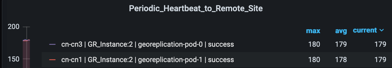
Heartbeat-Remote

-Site

critical

-

Communication Alarm

Expression: sum by (namespace)

(increase(geo_monitoring_total{ControlActionNameType=

'RemoteMsgHeartbeat',status!='success'}[1m])) > 0

Description: This alert is triggerd when periodic Heartbeat to remote site fails.

Local-Site-

POD-Monitoring

critical

-

Communication Alarm

Expression: sum by (namespace,AdminNode)

(increase(geo_monitoring_total{ControlActionNameType

='MonitorPod'}[1m])) > 0

Description: This alert is triggerd when local site pod monitoring failures breaches the configured threshold for the pod mentioned in Label:{{$labels.AdminNode}}.

PEER-Replication-

Immediate-

Local

critical

1

Communication Alarm

Expression: (sum by (namespace)

(increase(geo_replication_total{ReplicationNode='PEER',

ReplicationSyncType='Immediate',ReplicationReceiver='local',

ReplicationRequestType='Response',status='success'}

[1m]))/sum by (namespace) (increase(geo_replication_total

{ReplicationNode='PEER',ReplicationSyncType=

'Immediate',ReplicationReceiver='local',

ReplicationRequestType='Request'}[1m])))*100 < 90

Description: This alert is generated when the success rate of PEER sync type:Immediate and replication receiver:Local is below threshold value.

PEER-Replication-

Immediate-

Remote

critical

1

Communication Alarm

Expression: (sum by (namespace)

(increase(geo_replication_total{ReplicationNode='PEER',

ReplicationSyncType='Immediate',ReplicationReceiver='remote',

ReplicationRequestType='Response',status='success'}

[1m]))/sum by (namespace) (increase(geo_replication_total

{ReplicationNode='PEER',ReplicationSyncType='Immediate',

ReplicationReceiver='remote',ReplicationRequestType=

'Request'}[1m])))*100 < 90

Description: This alert is generated when the success rate of PEER sync type:Immediate and replication receiver:Remote is below threshold value.

RemoteCluster-

PODFailure

critical

-

Communication Alarm

Expression: sum by (namespace,AdminNode)

(increase(geo_monitoring_total{ControlActionNameType

='RemoteClusterPodFailure'}[1m])) > 0

Description: This alert is generated when pod failure is detected on the Remote site for the pod mentioned in Label:{{$labels.AdminNode}}.

RemoteMsg

NotifyFailover

critical

1

Communication Alarm

Expression: sum by (namespace,status)

(increase(geo_monitoring_total{ControlActionNameType

='RemoteMsgNotifyFailover',status!='success'}[1m])) > 0

Description: This alert is generated when transient role RemoteMsgNotifyFailover has failed for the reason mentioned in Label:{{$labels.status}}.

RemoteMsg

NotifyPrepare

Failover

critical

1

Communication Alarm

Expression: sum by (namespace,status)

(increase(geo_monitoring_total{ControlActionNameType

='RemoteMsgNotifyPrepareFailover',status!='success'}[1m])) > 0

Description: This alert is generated when transient role RemoteMsgNotifyPrepareFailover has failed for the reason mentioned in Label:{{$labels.status}}.

RemoteSite-

RoleMonitoring

critical

-

Communication Alarm

Expression: sum by (namespace,AdminNode)

(increase(geo_monitoring_total{ControlActionNameType

='RemoteSiteRoleMonitoring'}[1m])) > 0

Description: This alert is generated when RemoteSiteRoleMonitoring detects role inconsistency for an instance on the partner rack and accordingly changes the role of the respective instance on local rack to Primary. The impacted instance is in Label:{{$labels.AdminNode}}.

ResetRoleApi

-Initiated

critical

-

Communication Alarm

Expression: sum by (namespace,status)

(increase(geo_monitoring_total{ControlActionNameType

='ResetRoleApi'}[1m])) > 0

Description: This alert is generated when ResetRoleApi is initiated with the state transition of roles mentioned in Label:{{$labels.status}}.

TriggerGRApi

-Initiated

critical

-

Communication Alarm

Expression: sum by (namespace,status)

(increase(geo_monitoring_total{ControlActionNameType

='TriggerGRApi'}[1m])) > 0

Description: This alert is generated when TriggerGRApi is initiated for the reason mentioned in Label:{{$labels.status}}.

VIP-Monitoring

-Failures

critical

-

Communication Alarm

Expression: sum by (namespace,AdminNode)

(increase(geo_monitoring_total{ControlActionNameType

='MonitorVip'}[1m])) > 0

Description: This alert is generated when GR is generated upon detecting VIP monitoring failures for the VIP and Instance mentioned in the Label:{{$labels.AdminNode}}.

CDL Alerts

The following table list alerts for rule group CDL with interval-seconds as 60.

Table 16. Alert Rule Group - CDL

Alert Rule

Severity

Duration (in mins)

Type

GRPC-

Connections-

Remote-Site

critical

1

Communication Alarm

Expression: sum by (namespace, pod, systemId)

(remote_site_connection_status) !=4

Description: This alert is generated when GRPC connections to remote site are not equal to 4.

Inter-Rack

-CDL-Replication

critical

1

Communication Alarm

Expression: (sum by (namespace)

(increase(datastore_requests_total{local_request=\"0\",

errorCode=\"0\"}[1m]))/sum by (namespace)

(increase(datastore_requests_total{local_request=\"0\"}

[1m])))*100 < 90

Description: This alert is generated when the Inter-rack CDL replication success rate is below threshold value.

Intra-Rack

-CDL-Replication

critical

1

Communication Alarm

Expression: (sum by (namespace)

(increase(datastore_requests_total{local_request=\"1\",

errorCode=\"0\"}[1m]))/sum by (namespace)

(increase(datastore_requests_total{local_request=\"1\"}

[1m])))*100 < 90

Description: This alert is generated when the Intra-rack CDL replication success rate is below threshold.

Inter-site Geographic Redundancy

Inter-site geographic redundancy is the practice of implementing redundancy and failover mechanisms across multiple sites or locations. The purpose of inter-site redundancy is to ensure that critical services and applications remain available even in the event of a catastrophic failure at one site.

Feature Description

Mobile operators set up the redundant data centers in different geographical locations, so that if one data center goes down, the other can take over. This feature allows to extend the existing inter-rack solution to the inter-site solution. The current notation of HA inside a rack continues to work in conjunction with inter-site redundancy to provide a more comprehensive high availability solution.


Note


Inter-site and inter-rack solution cannot co-exist together, so customer need to select any one of the solutions.


Architecture

The SMF implements the 1:1 model of inter-site redundancy, also known as active:active model. This model is a type of redundancy configuration in which all sites in a network are actively processing traffic simultaneously, and each site is capable of taking over the full load of the network in case of a failure at another site.

The following topology diagram describes about the inter-site redundancy deployment architecture.

Prerequisites

Following is the list of the minimum site requirements for the 1:1 deployment model for each site:

  • Two leaves

  • Two spines

  • One K8 cluster with logical SMF containing two GR instances


    Note


    Each GR instance is the set of unique EPC, RADIUS, and N11 endpoints with same configuration in both the sites.


  • UPF would be deployed in 1:1 configuration


    Note


    Active and standby UPF instances are associated with GR instances, and UPF carries only N4 address of both the GR instances in control plane profile.


How It Works

Most of the configurations for the inter-rack and inter-site are same, except for the configurations that are required for managing and monitoring redundancy events, and replicating sessions across the sites.

Following are the guidelines to achieve the seamless communication between the sites in the inter-site redundancy implementation:

  • Prepend the autonomous systems (AS) path in the BGP (Border Gateway Protocol) route advertisement configuration. For more information, see Configuration for Inter-site Deployment.

  • L3 routing of the Geo-pod, CDL-ep (s), and CDL-Kafka-servers.

BGP Route Advertisement

In the inter-site redundancy deployment, the Multi-exit Discriminator (MED) attribute, which is a non-transitive BGP attribute, is used to inform the neighboring routers of the best path to reach the active service VIP. However, MED values are not shared beyond neighboring routers to their eBGP peers.

In the inter-rack deployment model, AS-path prepending technique is used in BGP to influence the path selection of routes advertised to other BGP routers. AS-path prepending technique makes a certain route more favorable over another by manipulating the AS-path in the BGP route advertisement. The difference in the number of AS-paths getting prepended by software logic helps to provide guidance to upstream routers to choose the best routable path.

Following table captures the number of AS-path prepend required for various combination of service VIP and interface bonding status.

GR Role Bonding interface active VIP present MED value

Local Preference

AS-Path Prepend (Number of times)

Primary Role (active) Yes Yes 1210 2220 3
Yes No 1220 2210 3
No Yes 1215 2215 3
No No 1225 2205 3
Standby Role Yes Yes 2210 1220 6
Yes No 2220 1210 6
No Yes 2215 1215 6
No No 2225 1205 6
Standby-Error Role NA NA 3220 220 9
KPI

prepend_as_path_count” label is added in the following existing metrics.

  • bgp_outgoing_failedrouterequest_total

  • bgp_outgoing_routerequest_total

The above metrics are populated when routes are advertised.

BGP Outgoing Failed Route Request KPI

KPI Name

Description

Labels

Possible Values

bgp_outgoing_failedrouterequest_total

This Key Performance Indicator (KPI) represents the total number of failed outgoing routes.

app_name Application Name
cluster Local
data_center

DC

instance 1
instance_id 1
interface

bd2.nrf.2275

local_pref 320

med

3220

next_hop

50.50.50.50

prepend_as_path_count

"9->STANDBY_ERROR"

service_IP

10.10.10.10

service_name

bgpspeaker-pod

vrf

Default

BGP Outgoing Route Request Total KPI

KPI Name

Description

Labels

Possible Values

bgp_outgoing_routerequest_total

This Key Performance Indicator (KPI) represents the total number of outgoing routes.

app_name Application Name
cluster Local
data_center

DC

instance 1
instance_id 1
interface

bd2.nrf.2275

local_pref 320

med

3220

next_hop

50.50.50.50

prepend_as_path_count

"9->STANDBY_ERROR"

service_IP

10.10.10.10

service_name

bgpspeaker-pod

vrf

Default


Note


The above metrics are populated when routes are advertised.


Values for As-Path metrics:

New label "prepend_as_path_count" includes the following values based on RoleInfo:

  • Inter Rack/Prepend CLI disabled:

    • prepend_as_path_count="Not-Applicable"

  • Prepend CLI enabled/Primary, Traffic_Hit reason:

    • prepend_as_path_count="0->PRIMARY,TRAFFIC_HIT"

  • Prepend CLI enabled/Primary, Non Traffic_Hit reason:

    • prepend_as_path_count="3->PRIMARY"

  • Prepend CLI enabled/STANDBY:

    • prepend_as_path_count="6->STANDBY"

  • Prepend CLI enabled/STANDBY_ERROR:

    • prepend_as_path_count="9->STANDBY_ERROR"

Configuration for Inter-site Deployment

To enable the inter-site deployment, you must configure the AS-path prepend flag in the BGP configuration.

Following is the sample configuration:

config 
  router local_as_number 
    bfd bfd_configuration 
    interface bgp_local_interface 
    prepend as-path { false | true } 
    exit 
   exit 

NOTES:

  • interface bgp_local_interface : Specify BGP local interface.

  • prepend as-path { false | true } : Select true to enable the Inter-site deployment. By default this option is disabled.

    If this option is set to false , the logical SMF deployment follows the inter-rack model.

Configuration Verification

To verify the configuration, use the following show command:

smf# show running-config router 
router bgp 63200
 learnDefaultRoute false
 prepend as-path true  ——————————————————> as-path
 bfd interval 250000 min_rx 250000 multiplier 3
 interface enp216s0f0.2119
  bondingInterface enp216s0f0
  bondingInterface enp94s0f0
  neighbor 101.101.172.254 remote-as 63100 fail-over bfd
 exit
 interface enp216s0f0.2129
  vrf vrf_papn1
  bondingInterface enp216s0f0
  bondingInterface enp94s0f1
  neighbor 101.101.174.254 remote-as 63100 fail-over bfd
 exit
 interface enp216s0f0.2139
  vrf vrf_papn2
  bondingInterface enp216s0f0
  bondingInterface enp94s0f0
  neighbor 101.101.178.254 remote-as 63100 fail-over bfd
 exit 

Following is the sample ouput of the bgp-advertised routes corresponding to the GR role.

[smf] smf# show role instance-id 1
result "PRIMARY"
[smf] smf# show bgp-advertised-routes 
bgp-route 

-----bgpspeaker-pod-0 ----
   Network              Next Hop                 AS_PATH          Age        Interface        Vrf                       Attrs
*> 209.165.200.228    209.165.200.229       63000 63000 63000   00:00:47      ens161         Default      [{Origin: e} {LocalPref: 2205} {Med: 1225}]

L3 Routing of Pods

In the inter-rack solution, leaf and spine servers were incorporated into the same AS-path to enable the utilization of VxLAn techniques. This deployment model allows for the support, monitoring, and exchange of redundancy data and events among various pods, while remaining reachable across racks. Specifically, the external IP address of the Geo-pod on both racks were integrated into a common subnet, enabling data exchange without the need for route discovery as they shared the same VLAN. Additionally, communication between racks remained within the boundaries of the leaf and spine servers, without the need for packets to traverse beyond them.

The following PODs require external connectivity between the sites:

  • Geo-pod

  • CDL-ep (s)

  • CDL-Kafka-server(s)

Unlike service VIPs, these IP addresses do not require floating across sites. A routing decision needs to be made only once during production deployment. Therefore, static routing was used instead of advertising these external IP addresses through BGP.

Static routes are added to the local K8S cluster protocol nodes for reaching remote CDL/Kafka/Geo Networks. The leafs automatically advertise all connected local CDL/Kafka/Geo Networks to the spines. The spines redistribute those routes to the Arg router. The Arg routers know how to reach both Sites' CDL/Kafka/Geo Networks. If a packet is destined for a remote CDL/Kafka/Geo network, the local K8S protocol node has a static route that points to the local leaf. The packet then goes to the spine. The spines have a default route that points to the Arg router. The Arg routers have proper routes to send packets to the remote site.

In addition, the Arg routers are configured with the "default-originate" keyword, which designates the ARG routers as the default gateway for the spines. Consequently, the spines redirect all traffic for which a routing path is not available in the spines to the Arg routers.

Inter-site Redundancy Scenarios

This section describes that how the inter-site redundancy deployment works in the different scenarios:

In a scenario with two sites and both operational, each site have one primary/active GR (Gateway Router) instance. The endpoint configured on each site carries traffic corresponding to its active instance. It is possible that the Aggregation Router (ARG) may not be directly connected to the sites, and there could be multiple autonomous systems between the ARG and sites. The ARG router is responsible for the convergence of the routes from both sites.

Following are the various scenarios for the site redundancy:

  • During sunny weather conditions, Site A advertises the best route for GR1 and a less favorable route for the endpoint associated with GR2.

    On the ARG, following are the routes:

    • Routes from Site A

      • 209.165.200.225 AS-Path 65000 65000 65000 65000

      • 209.165.200.235 AS-Path 65000 65000 65000 65000 65000 65000 65000

    • Routes from Site B

      • 209.165.200.225 AS-Path 64000 64000 64000 64000 64000 64000

      • 209.165.200.235 AS-Path 64000 64000 64000 64000

    • Best Path:

      • Site-A 209.165.200.225 AS-path 65000 65000 65000 65000

      • Site -B 209.165.200.235 AS-path 64000 64000 64000 64000

Now if the Site A goes down:

The BGP session on the ARG routers goes down after the BGP convergence time, resulting in the withdrawal of routes learned from Site A. The current state of routes at ARG is as follows.

  • Routes from Site B:

    • 209.165.200.225 AS-Path 64000 64000 64000 64000 64000 64000 64000

    • 209.165.200.235 AS-Path 64000 64000 64000 64000

    Now the traffic for both the endpoints 209.165.200.225 and 209.165.200.225 is being sent towards site B.

  • The traffic monitoring feature at site B has identified traffic for the IP address 209.165.200.225. Once the packet threshold for this IP address is exceeded, the GeoReplication pod triggers the transition of the GR-1 instance from standby mode to active mode.

  • After the Geo-pod notifies the BGPSpeaker-pod of the transition of GR1 to the primary instance, the BGPSpeaker-pod readvertises the routes for the GR1 endpoint using the most favorable routing path.

  • Now the routes in the ARG are updated with following information:

    • Routes from site B:

      • 209.165.200.225 AS-Path 64000 64000 64000 64000

      • 209.165.200.235 AS-Path 64000 64000 64000 64000

Split Brain

When deploying across multiple sites, the failure domain expands. Failures that occur within the leaf/spine architecture and rack are well-managed, and the state of the GR instances during these failures is well-defined and follows the same mechanism as the Inter-Rack solution. However, if there are failures outside the data center, such as link fluctuations on external routers, there is no mechanism for the rack with an active GR instance in cases where communication with the peer rack is lost.

If the link between the Client Router and Data Center Router goes down, connectivity between the racks is lost. The Client Router then sends incoming data traffic to the next preferred site, which is Site 2 in this case. Site 2 has traffic monitoring enabled, which detects the traffic, and once the incoming traffic threshold is met, the GR instance is transitioned from Standby to Primary. At this point, both Site 1 and Site 2 are active for this GR instance. If the link between ARG-Site1 and the Client Router is restored, a dual-active or split-brain scenario occurs.

This instance leads to the following scenarios:

  1. If the Client Router distributes traffic between ARG-Site1 and ARG-Site2, it results in call loss and disruptions in customer service.

  2. Post external link recovery, which site to consider primary and how to move the other site to standby.

To address the issue of traffic being distributed between the two sites, solution is to not prepend any AS-path when the GR instance transitions from standby to Primary due to traffic monitoring. The new Primary site then performs the BGP readvertising without any explicit local AS path pre-pending, making this site the most preferred even if the peer site comes back online. This approach ensures that traffic is directed to the Primary site until the Secondary site is restored and fully operational.

To address the issue of Site Role transition after external link recovery, solution is to keep a timestamp for every role transition. When the link is restored, communication occurs between the Site-1/Geo-Pod and Site-2/Geo-Pod, during which both the pods exchange the role state and timestamp on which the transition occurred. The site with the older timestamp then transitions from Primary to Standby, ensuring that the most recent Primary site maintains its role after the link is restored.


Note


The timestamp update happens only when there is a change in the role. If there is a change in the reason, the timestamp remains unchanged. When detecting the initial split brain, the preference is given for the Site/Rack combination with the role primary and the reason traffic-hit.


KPI

As part of this feature, the following Key Performance Indicators (KPIs) are associated with split brain support.

Geo Split Brain Detection Total KPI

KPI Name

Description

Labels

Possible Values

geo_split_brain_detection_total

This Key Performance Indicator (KPI) represents the overall count of Split Brain Detection instances.

GRInstanceNumber

It's the GR Instance ID and value can be any one from the following:

  • instance.1

  • instance2.

LocalSiteRole

This is local site’s role as a number. This can be any one of below values:

  • 2 (for Primary role)

  • 3 (for Standby role)

  • 6 (for Standby-error role)

LocalSiteReason

This is local site’s reason’s string value:

  • "CLI"

  • "BFD Failure"

  • "POD Failure"

  • "TRAFFIC Hit"

  • "UPGRADE"

  • "STARTUP"

  • "STUCKED Role"

  • "SITE Notification"

  • "REMOTE Monitoring"

  • "SPLITBRAIN Recover"

  • "DELETE Notification"

  • "HEARTBEAT Recover"

LocalSiteTimeStamp Local site’s timestamp when role was last updated.
RemoteSiteRole This is remote site’s role as a number. This can be any one of below values:
  • 2 (for Primary role)

  • 3 (for Standby role)

  • 6 (for Standby-error role)

RemoteSiteReason

This is remote site’s reason’s string value:

  • "CLI"

  • "BFD Failure"

  • "POD Failure"

  • "TRAFFIC Hit"

  • "UPGRADE"

  • "STARTUP"

  • "STUCKED Role"

  • "SITE Notification"

  • "REMOTE Monitoring"

  • "SPLITBRAIN Recover"

  • "DELETE Notification"

  • "HEARTBEAT Recover"

RemoteSiteTimeStamp Remote site’s timestamp when role was last updated.

Geo Split Brain Resolution Total

KPI Name

Description

Labels

Possible Values

geo_split_brain_resolution_total

This Key Performance Indicator (KPI) represents the overall count of split brain resolution instances.

GRInstanceNumber

It's the GR Instance ID and value can be any one from the following:

  • instance.1

  • instance2.

LocalSiteRole

This is local site’s role as a number. This can be any one of below values:

  • 2 (for Primary role)

  • 3 (for Standby role)

  • 6 (for Standby-error role)

LocalSiteReason

This is local site’s reason’s string value:

  • "CLI"

  • "BFD Failure"

  • "POD Failure"

  • "TRAFFIC Hit"

  • "UPGRADE"

  • "STARTUP"

  • "STUCKED Role"

  • "SITE Notification"

  • "REMOTE Monitoring"

  • "SPLITBRAIN Recover"

  • "DELETE Notification"

  • "HEARTBEAT Recover"

LocalSiteTimeStamp Local site’s timestamp when role was last updated.
RemoteSiteRole This is remote site’s role as a number. This can be any one of below values:
  • 2 (for Primary role)

  • 3 (for Standby role)

RemoteSiteReason

This is remote site’s reason’s string value:

  • "CLI"

  • "BFD Failure"

  • "POD Failure"

  • "TRAFFIC Hit"

  • "UPGRADE"

  • "STARTUP"

  • "STUCKED Role"

  • "SITE Notification"

  • "REMOTE Monitoring"

  • "SPLITBRAIN Recover"

  • "DELETE Notification"

  • "HEARTBEAT Recover"

RemoteSiteTimeStamp Remote site’s timestamp when role was last updated.

OldRole

The role before split-brain resolution. This can be any one of below values:

  • 2 (for Primary role)

  • 3 (for Standby role)

NewRole

The new role after split-brain resolution. This can be any one of below values:

  • 3 (for Standby role)

  • 6 (for Standby-error role)

Geo Role Reason Change Total

KPI Name

Description

Labels

Possible Values

geo_role_reason_change_total

This Key Performance Indicator (KPI) represents the overall count of the total number of times the role reason has been changed to HEARTBEAT Recover.

GRInstanceNumber

It's the GR Instance ID and value can be any one from the following:

  • instance.1

  • instance2.

LocalSiteRole

This is local site’s role as a number. This can be any one of below values:

  • 2 (for Primary role)

  • 3 (for Standby role)

  • 6 (for Standby-error role)

oldReason

This is local site’s reason’s string value before HEARTBEAT Recover:

  • "HEARTBEAT Recover"

NewReason

This is local site’s reason’s string value:

  • "HEARTBEAT Recover"

Note


Currently, this transition occurs exclusively based on Traffic Hit.