Wi-Fi Handovers

Feature Summary and Revision History

Summary Data

Table 1. Summary Data

Applicable Product(s) or Functional Area

SMF

Applicable Platform(s)

SMI

Feature Default Setting

Disabled – Configuration Required

Related Changes in this Release

Not Applicable

Related Documentation

Not Applicable

Revision History

Table 2. Revision History
Revision Details Release

FB Call Continuity Cause Code Expansion

2021.02.2

Added support for:

  • Configuring calls with handover indication.

  • UE Local IP Address and UE UDP Port IEs in GTPC messages.

2021.02.0

TFT Handling for Wi-Fi Handovers is supported.

2021.01.0

The Wi-Fi to 5GS Handover with EPS Fallback feature is fully qualified in this release.

2020.02.2

The Wi-Fi to 5GS Handover with EPS Fallback feature is not fully qualified in this release. For more information, contact your Cisco Account representative.

2020.02.1

First introduced.

Pre-2020.02.0

Feature Description


Important

The PGW-C term used in this chapter denote the EPS interworking functionality supported by SMF and must not be assumed as a standalone P-GW that is used in the LTE network.


The SMF+PGW-C product supports Wi-Fi handovers. The cloud-based architecture supports the following Wi-Fi handovers in 5GS or EPS and non-3GPP untrusted access.

  • EPC to non-3GPP untrusted Wi-Fi handover

  • Non-3GPP untrusted Wi-Fi to EPC handover

  • Non-3GPP untrusted Wi-Fi to 5GS handover with EPS fallback

  • Non-3GPP untrusted Wi-Fi to 5GS handover

  • 5GS to non-3GPP untrusted Wi-Fi handover

Handover Indication Support

The SMF+IWF rejects the Create Session Request received with handover (HO) indication even if the session does not exist. This support is applicable only to the 4G and Wi-Fi sessions.

The gtpc message-handling create-session-request ho-ind new-call-reject CLI command under access profile rejects the call with "Context Not Found".

For more information, see the Configuring Calls with Handover Indication section.

Architecture

The following sections describe the architecture for interworking between the ePDG or EPC and 5GS and the nonroaming architecture within the EPS using S5 and S2b interfaces.

ePDG and 5GS Interworking for Handover

The following figure illustrates the non-roaming architecture for interworking between the ePDG or EPC and 5GS.

Figure 1. Non-roaming Architecture for Interworking between ePDG or EPC and 5GS

The interworking between the ePDG and 5GS is similar to the interworking between the EPC and 5GS without the N26 interface. In this interworking, the IP address preservation occurs on the UEs on inter-system mobility. Fetching and saving the PGW-C and SMF and the corresponding APN and DNN information through the HSS and UDM makes interworking possible. In such networks, the AMF also supports interworking with UEs without the N26 interface during the initial registration in 5GC. The AMF may support interworking with UEs without N26 in the Attach procedure in 5GS. In case of a non-3GPP untrusted Wi-Fi access, the ePDG does not communicate with the AMF because the N26 interface does not exist.

A 5GS supports network slicing and can interwork with the EPS in its PLMN or in other PLMNs. The SMF+PGW-C performs UDM registration for each UE with PGW-C FQDN and NSSAI values. With this registration, the AMF or ePDG identify the PGW-C IP-address from the UDM or HSS as part of the subscription information after the UE authorization is completed.

The mobility between 5GC to EPC does not ensure that all the active PDU sessions can be transferred to the EPC. During PDN connection establishment in the EPC, the UE allocates the PDU session ID and sends it to the PGW-C+SMF through the PCO.

An S-NSSAI that is associated with the PDN connection is determined based on the operator policy by the PGW-C+SMF. For example, the combination of PGW-C+SMF address and APN is sent to the UE in the PCO along with a PLMN ID to which the S-NSSAI relates. If the PGW-C+SMF supports multiple S-NSSAI and the APN is valid for multiple S-NSSAIs, the PGW-C+SMF selects only the S-NSSAI that is mapped to the subscribed S-NSSAIs of the UE.

The UE saves the S-NSSAI and the PLMN ID that is associated with the PDN connection. The UE derives the requested NSSAI through the received PLMN ID. The NAS registration request message includes the requested NSSAI. The RRC carries the registration request when the UE registers in 5GC. This scenario is applicable if the UE is non-roaming or the UE has configured NSSAI for the VPLMN in roaming case.

EPS and ePDG Interworking for Handover

The following figure illustrates the non-roaming architecture within the EPS using S5 and S2b interfaces.

Figure 2. Non-roaming Architecture Within EPS using S5, S2a, and S2b Interfaces

This image 4414891.jpg is not available in preview/cisco.com

Figure 3. Non-roaming Architecture Within EPS using S5, S2a, and S2b Interfaces

For 3GPP access to non-3GPP access untrusted Wi-Fi handover and for non-3GPP access untrusted Wi-Fi to 3GPP access handover, if a UE has multiple PDN connections to different APNs in the source access and the UE can route different simultaneously active PDN connections through different access networks, the UE can transfer from the source to the target access all the PDN connections that were active in source access before handover or only a subset of them. This transfer can have the restriction that multiple PDN connections to the same APN have one access.

The transfer process can occur in the following scenarios:

  • 3GPP access to non-3GPP access untrusted Wi-Fi handover

  • Non-3GPP access untrusted Wi-Fi to 3GPP access handover

The UE can transfer from the source to the target access all the PDN connections that were active in source access before handover or only a subset of them if the following conditions are met:

  • The UE has multiple PDN connections to different APNs in the source access

  • The UE can route different, but simultaneously active, PDN connections through different access networks."

The SMF supports untrusted Wi-Fi access for end-users over S2b interface with ePDG after establishment of IPSec connection between the end-user and ePDG.

For untrusted Wi-Fi to EPC handover, the SMF provides a PGW-C FQDN during UDM registration and fetches the subscription information.

During UE handover, the MME fetches PGW-C FQDN from the HSS. After authentication, the MME initiates GTPv2 create session request indicating handover. The SMF+PGW-C does not perform the UDM registration and subscription procedures while processing handover request. SMF+PGW-C ensures that GTPv2 MB request indicating handover is sent to perform data path switching from untrusted Wi-Fi to EPC.

For EPC to untrusted Wi-Fi handover, the HSS provides SMF+PGW-C FQDN after the subscriber authentication. When UE performs handover, after authentication HSS provides SMF+PGW-C FQDN. The ePDG initiates GTPv2 create session request indicating handover toward PGW after IPSec tunnel establishment. SMF+PGW-C performs the UDM registration and no subscription procedures exist while processing the handover request.

TFT Handling for Wi-Fi Handovers

In 4G and 5G deployment, the three-way audio or video multiparty call conference, and RCS message use cases, PGW-C ends up having more than four filters (it can go upto max 16 filters) for both UL and DL direction. SMF includes “EPS Bearer Level Traffic Flow Template (Bearer TFT)” is included in the GTPv2 CBReq or UBReq of BearerContextList. CBReq or UBReq carry maximum of 4 TFTs per bearer.

In case of three-way Audio/Video and multiparty call-conference, PCF tries to push the pccRules by adding different subscriber TFTs in multiple “N7 Policy Notify Req” messages. PGW-C handles the received “N7 Update Notify Req” in dedicated bearer establishment or update towards Wi-Fi or LTE by initiating GTPv2 CBReq or UBReq messages. SMF accommodates the received SDF Filters in TFT as it never crosses more than 256 Bytes (4 TFTs).


Note

PGW-C don’t support more than 4TFTs received from PCF “N7 Policy Notify Req”.


PCF keeps pushing multiple pccRules for same bearer by sending “N7 Policy Notify Req” and over the period SMF ends up having 12-16 filters for case of multiparty call.

When subscriber moves from LTE to Wi-Fi or Wi-Fi to LTE or NR to Wi-Fi Handover call-model cases, SMF first establishes default bearer creation as part of HO. SMF then tries to send out CBReq for Dedicated bearer establishment by accommodating all 16 filters in “EPS Bearer Level Traffic Flow Template (Bearer TFT)” of bearer context list of the subscriber and if it fails to encode because of these restrictions. The SMF sends out CBReq without “EPS Bearer Level Traffic Flow Template (Bearer TFT)” IE based on HO type, SGW, MME, or ePDG rejects GTPv2 CBResp with Mandatory IE Incorrect with “TFT Semantic Errors”.

After receiving CBResp from SGW or ePDG, SMF doesn’t free up policy or charging resources for respective failed bearers and that leads to further stale entries on SMF and UPF which leads to system inconsistency for that subscriber with “EBI Mismatch – 408 Error Voice Call Failure Wi-Fi HOs”.

Standards Compliance

The Wi-Fi handovers feature complies with the following standards:

  • 3GPP TS 23.502 V15.2.0 (2018-09)

  • 3GPP TS 23.402 V15.3.0 (2018-03)

  • 3GPP TS 29.214 V15.5.0 (2018-03)

How it Works

This section describes the Wi-Fi to LTE handover, Wi-Fi handover with EPS fallback, and Wi-Fi to 5GS handover.

EPC to Non-3GPP Untrusted Wi-Fi Handover Call Flow

This section describes the EPC to non-3GPP untrusted Wi-Fi handover call flow.

Figure 4. EPC to Non-3GPP Untrusted Wi-Fi Handover Call Flow
Table 3. EPC to Non-3GPP Untrusted Wi-Fi Handover Call Flow Description
Step Description
1

The UE is attached to the 3GPP access network.

The SMF+PGW-C communicates with UPF, PCF, and CHF for IPv4, IPv6, or dual-stack to establish 4G LTE PDU session. The PCF sends the Policy Control Request trigger, which is the SM policy decision, in response to SM policy control create. The CHF provides session-level or rating-group-level triggers to the SMF in Charging Data Create response.

2 The UE connects to an untrusted non-3GPP access and an ePDG is selected through the ePDG selection process. Then, the UE initiates the handover attach procedure as defined in 3GPP TS 23.402, section 8.6.2.1. After the IKE tunnel is established between the UE and ePDG and after the UE is authenticated over SWm interface with AAA server, the UE initiates IKE authentication (IKE_AUTH). The IKE_AUTH includes configuration parameters of the earlier assigned IPv4 or IPv6 addresses in the EPC and P-CSCF and the DNS options.
3

The ePDG sends a Create Session Request to the PGW-C. This request includes the following details:

  • IMSI

  • APN

  • Handover indication

  • RAT type

  • ePDG TEID of the Control Plane

  • ePDG address for the User Plane

  • ePDG TEID of the User Plane

  • EPS bearer identity

  • User location

The RAT type indicates the non-3GPP access technology type. If the UE supports the IP address preservation and is included in the port analyzer adapter (PAA), then the ePDG configures the handover indication in the Create Session Request to allow the PDN gateway to reallocate the same IP address or the prefix assigned to the UE. This IP address or prefix is assigned while UE is connected to the 3GPP IP access and initiates the policy modification procedure with PCF.

4a

The SMF performs UDM registration by updating the PGW-C FQDN with UDM.

The UDM registration does not occur during the session establishment with EPC.

4b The SMF detects the charging triggers with the information available in Step 3 against the charging triggers that are received during EPC session establishment.
4c The SMF detects the PCF triggers with the information available in Step 3 against the Request Policy Control triggers that are received in the communication with PCF during EPC session establishment.
5 Based on the detected armed Policy Control Triggers that are received in Step 4b, the SMF sends the SM Policy Control Update request with the detected access parameters in Step 3 to the PCF.
6 The PCF includes new or updated PCC rules and sends the SM Policy Control Update response. The Update response includes information on the SM policy decision.
7 Based on the information received in Step 6 and existing policy data of EPC session, SMF prepares the information for the new or updated PCC rules.
8 If new PCC rules are received in Step 6 with new Rating Group that requires quota information, SMF sends the Charging Update request to CHF. SMF also includes new access parameters for the PDU session information.
9 CHF sends the Charging Update Response with multi-unit information that contains quota information for the requested rating-group in Step 8 to SMF. CHF may also send the new quota information for the existing rating-group of EPC session.
10 SMF processes the information that is received as Charging Update response from CHF.
11 SMF sends the N4 session modification request to UPF for Wi-Fi tunnel. This request includes details on creation of uplink PDR, creation of QER, creation of URR for received new rating-group quota information, and update on URR for modified quota information.
12 UPF sends the UL tunnel information that is in created PDR as the N4 session modification response to SMF.
13 SMF sends the GTPv2 Create Session response to S-GW. This response details on request accepted or request accepted partially, PGW-C S2b F-TEID, PAA, APN-AMBR, bearer context creation, charging gateway address, and APCO.
14 SMF sends the GTPv2 Create Bearer request to S-GW. This request includes information on bearer context list, which contains DL tunnel information to end-user, to be created.
15 S-GW sends the GTPv2 Create Bearer response to SMF. The response includes details on request accepted or request accepted partially and bearer contexts.
16 SMF processes the Create Bearer response and derives the DL tunnel Information for the established bearer and the the failed EBI list, if any. SMF sends the N4 session modification request to UPF for Wi-Fi tunnel. This request is to create the DL PDR and DL FAR with DL tunnel information for each bearer, RAT modification information, and to delete resources for the 4G tunnel. SMF also deletes the N4 resources of Wi-Fi tunnel for the received failed EBI list or the failed QFI list.
17 UPF sends the usage report as N4 Session Modification response to SMF.
18 SMF+PGW-C sends the GTPv2 DB request to S-GW. This request includes EBI or list of EBIs.
19 S-GW sends the GTPv2 DB response to SMF+PGW-C.
20 SMF sends the Charging Update request to CHF. This request includes the PDU session information with the new access params and multi-usage report containing details on the access params and usage report that is received in Step 8
21 CHF sends the multi-unit information as Charging Update response to SMF. The multi-unit information may include new quota information for the existing rating-groups.
22

SMF sends the SM Policy Control Update request to UPF. This request includes the new access params and rule report for failed QFI list that is received from AMF as part of Create Bearer response.

PCF sends the SM policy decision as SM Policy Control Update response.

SMF processes the SM policy decision and handles it as PCF Initiation Modify procedure as defined in 3GPP 23.502, section 4.3.3.2.

Non-3GPP Untrusted Wi-Fi to EPC Handover Call Flow

This section describes the non-3GPP untrusted Wi-Fi to EPC handover call flow.

Figure 5. Non-3GPP Untrusted Wi-Fi to EPC Handover Call Flow
Table 4. Non-3GPP Untrusted Wi-Fi to EPC Handover Call Flow Description
Step Description
1 One or more PDU sessions are established between UE and ePDG through untrusted non-3GPP access. With the 5G NAS capability of UE, ePDG selects a combined PGW+SMF. UE sends the PDU session ID to the PGW+SMF.
2

UE discovers the E-UTRAN access and hands over the sessions from the currently used non-3GPP access system to E-UTRAN. For details on UE discovery of the 3GPP access system, see 3GPP TS 23.401, section 4.8.

UE sends an Attach request to MME for the Handover Attach request type. E-UTRAN routes the messages received from UE to MME as defined in 3GPP TS 23.401. UE includes the one of the APNs which are corresponding to the PDN connections in the source non-3GPP access. The APN is provided as defined in 3GPP TS 23.401.

3

MME and HSS perform authentication, which is followed by location update procedure and subscriber data retrieval to receive the APN information.

The MME selects an APN, an SGW and PDN gateway as defined in 3GPP TS 23.401. MME sends a Create Session Request message to SGW. This request includes information on IMSI, MME context ID, PDN-GW address, handover indication for the “handover” request type, and APN.

4

SGW sends a Create Session Request, which is handover indication, message to PDN-GW in the HPLMN as described in 3GPP TS 23.401. As the MME includes the handover indication information in the Create Session Request message, the SGW sends the GTPv2 Create Session Request message to PDN GW. This message includes details on IMSI, APN, handover indication, RAT type, S5-C TEID, S5-U TEID of the user plane, EBI, and user location information. The RAT type indicates the 3GPP IP access E-UTRAN technology type. If the UE supports IP address preservation and is included in PAA, the SGW configures the handover indication in the Creation Session Request. With this configuration, the PDN GW re-allocates the same IP address or prefix that was assigned to the UE while it was connected to the 3GPP IP access. With this configuration, SGW initiates the Policy Modification Procedure to the PCF.

As the handover indication is includes, the PDN GW does not switch the tunnel from non-3GPP IP access to 3GPP access system at this point.

SMF does not perform the UDM Registration as the registration happens during the Wi-Fi session establishment.

4a SMF detects the charging triggers with the information available in Step 3 against the charging triggers that are received during EPC session establishment.
4b SMF detects the PCF triggers with the information available in Step 3 against the Request Policy Control triggers that are received in the communication with PCF during EPC session establishment.
5 Based on the detected armed Policy Control Triggers that are received in Step 4b, SMF sends the SM Policy Control Update request with the detected access parameters in Step 3 to PCF.
6 PCF sends the SM Policy Control Update response, which is the SM policy decision, by including new or updated PCC rules.
7 Based on the information received in Step 6 and existing policy data of EPC session, SMF prepares the information for the new or updated PCC rules.
8 If SMF receives new PCC rules in Step 6, the SMF sends the Charging Update request, with the new rating-group having quota information, to CHF. This request includes the PDU session information with the new access params.
9 CHF sends the multi-unit information as Charging Update response to SMF. The multi-unit information includes new quota information for the rating-group and the existing rating-group of EPC session, if any.
10 SMF prepares the charging data of the received Charging Update Response that CHF sent.
11 SMF sends the N4 Session Modification Request to UPF. This request includes the details on creation of UL and DL PDR, creation of QER, creation of URR for received new rating-group quota information, updated URR for modified quota information, and creation of FAR.
12 UPF sends the UL tunnel information in the created PDR as N4 Session Modification response to SMF.
13 SMF sends the GTPv2 Create Session response to S-GW. This response details on request accepted or request accepted partially, PGW-C S2b F-TEID, PAA, APN-AMBR, bearer context creation, charging gateway address, and APCO.
14 SGW sends the Modification Bearer request with handover indication to PGW for data path switching from Wi-Fi tunnel to 4G tunnel.
15 PGW sends the N4 Session Modification request to delete the Wi-Fi tunnel and to configure DL tunnel information that is received in GTPv2 Create Session request for 4G tunnel in Step 4.
16 UPF sends the N4 Session Modification response to SMF.
17 SMF sends the GTPv2 Create Session request, which includes the bearer context list, to SGW. This list includes the DL Tunnel information for the end-user.
18 SGW sends the GTPv2 Create Session response to SMF. This response includes details on request accepted or request accepted partially and bearer contexts.
19 ePDG sends the GTPv2 Create Bearer resp (accepted EBIs with DL tunnel info to SMF
20 SMF processes the Create Bearer response and derives the DL tunnel Information for the established bearer and the failed EBI list, if any. SMF sends the N4 session modification request to UPF for Wi-Fi tunnel. This request is to update the DL FAR with the DL tunnel information, RAT modification information, and to delete resources for the 4G tunnel. SMF also deletes the N4 resources of Wi-Fi tunnel for the received failed EBI list or the failed QFI list.
21 UPF sends the N4 Session Modification Response with usage report to SMF.
22 SMF sends the Charging Update request to CHF. This request includes the PDU session information with new access params and multi-usage report consisting of access-params and usage report that is received in Step 8.
23 CHF sends the Charging Update Response with multi-unit information that contains quota information for the existing rating-groups to SMF.
24 SMF+PGW-C initiates the GTPv2 DB Request toward SGW by including EBI or EBI list.
25 SGW sends the GTPv2 DB Response toward SMF+PGW-C.
26

SMF sends the SM Policy Control Update request to UPF. This request includes the new access params and rule report for failed QFI list that is received from AMF as part of Create Bearer response.

PCF sends the SM policy decision as SM Policy Control Update response.

SMF processes the SM policy decision and handles it as PCF Initiation Modify procedure as defined in 3GPP 23.502 section 4.3.3.2.

Non-3GPP Untrusted Wi-Fi to 5GS Handover with EPS Fallback Call Flow

This section describes the non-3GPP untrusted Wi-Fi to 5GS handover with EPS fallback call flow.

Figure 6. Non-3GPP Untrusted Wi-Fi to 5GS Handover with EPS Fallback Call Flow
Table 5. Non-3GPP Untrusted Wi-Fi to 5GS Handover with EPS Fallback Call Flow Description

Step

Description

1

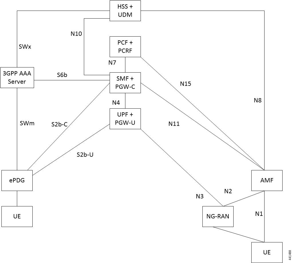
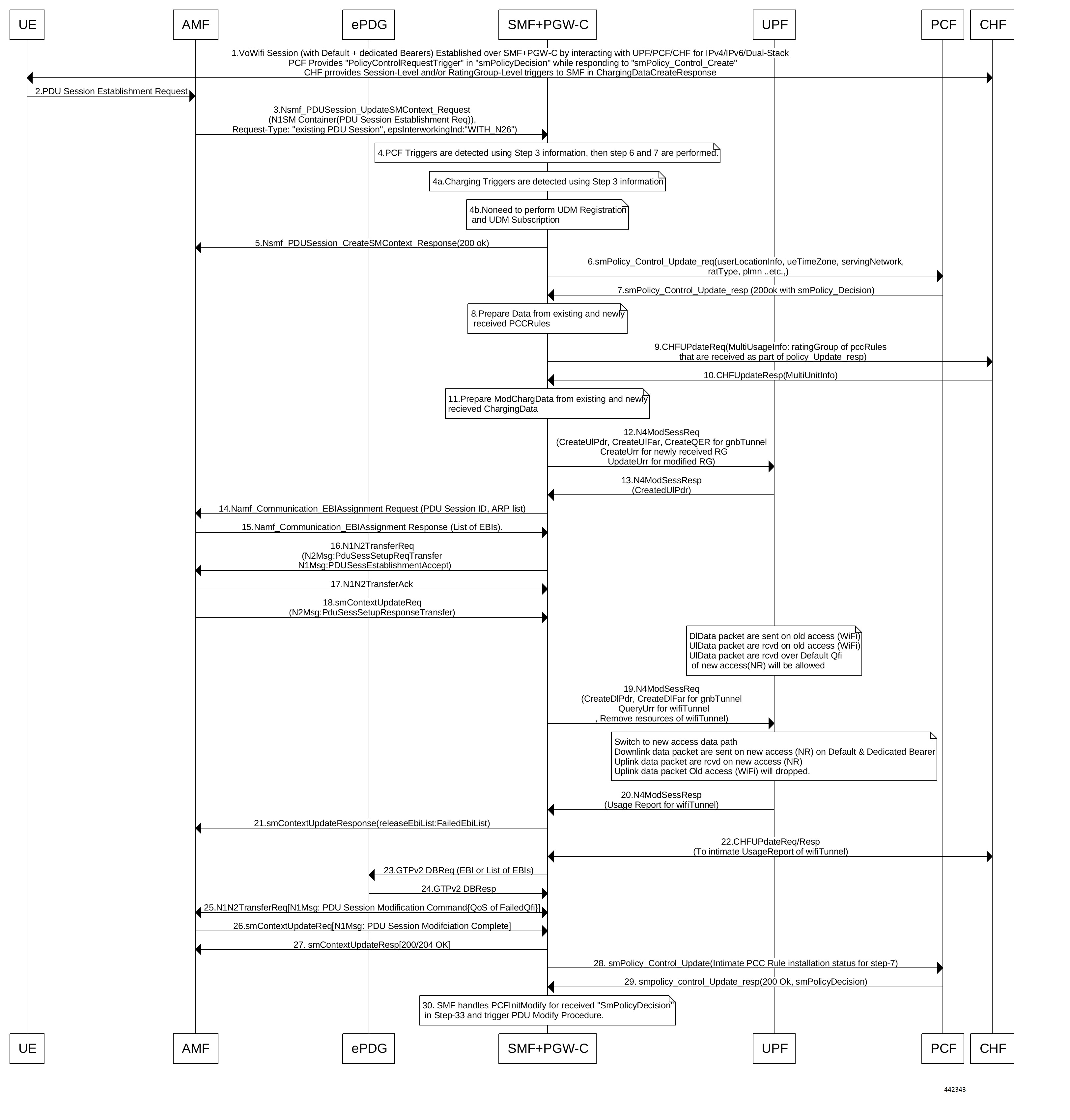
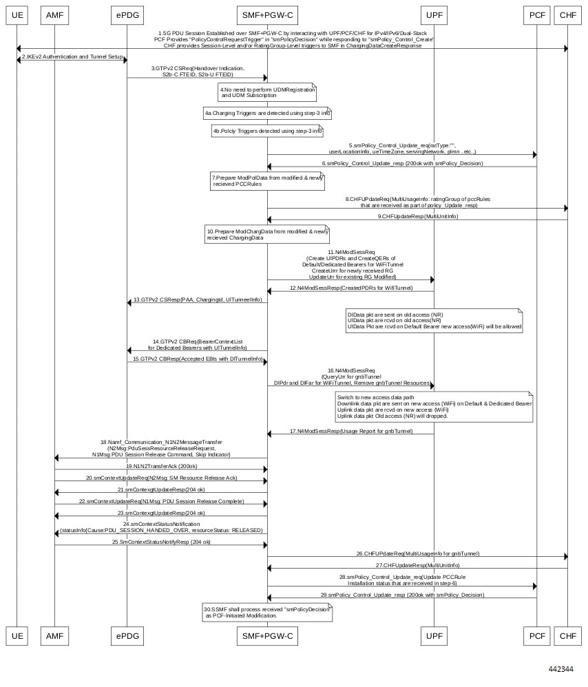
The UE and the ePDG interact with each other through untrusted non-3GPP access to establish one or more PDU sessions. With the 5G NAS capability of UE, ePDG selects a combined PGW-C and SMF. The UE sends the PDU session ID to the combined PGW-C and SMF.

1a

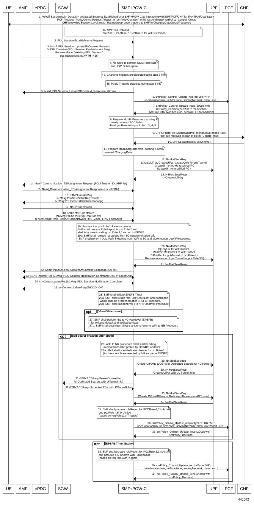
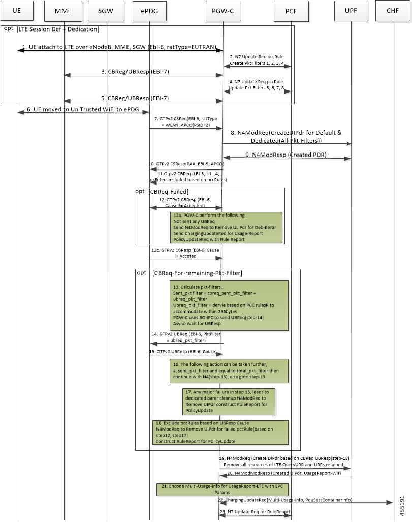
The SMF installs the PccRule-1, PccRule-2, PccRule-3 for the WiFi session.

2

The AMF sends the PDU Session Establishment request through 3GPP access to the SMF. This request includes details on the following:

  • PDU session ID

  • Requested PDU session type

  • Requested SSC mode

  • 5GSM capability PCO

  • SM PDU DN request container

  • Number of packet filters

  • Optional requested always-on PDU session

The request type with an existing PDU session indicates switching between 3GPP access and non-3GPP access or to a PDU session handover from an existing PDN connection in EPC.

3

If the request type is “Existing PDU Session”, the AMF selects the SMF based on SMF-ID that is received from the UDM.

An error occurs for this request type on meeting any of the following conditions:

  • If the AMF does not identify the PDU Session ID or the subscription context that the AMF received from UDM during the registration.

  • If the subscription profile update notification procedure contains no SMF ID corresponding to the PDU Session ID.

Then, the AMF updates the Access Type stored for the PDU session.

If the request type with an existing PDU session refers to a PDU session that moved between 3GPP access and non-3GPP access and if the S-NSSAI of the PDU session is available in the Allowed NSSAI of the target access type, the PDU Session Establishment procedure begins when the SMF ID corresponding to the PDU Session ID and the AMF are part of the same PLMN.

The AMF sends the NSMF PDU Session Create SM Context request with the request type “Existing PDU Session” to the SMF. This request includes information on the following:

  • SUPI

  • DNN

  • S-NSSAIs

  • PDU Session ID

  • AMF ID

  • Request Type

  • PCF ID

  • Priority Access

  • N1 SM container including the PDU Session Establishment Request

  • User location information

  • Access Type

  • PEI

  • GPSI

  • Subscription For PDU Session Status Notification

  • DNN Selection Mode

The SMF analyzes the existing PDU session from the PDU Session Establishment request using SUPI+PDU-Session-ID. The SMF also compares the IPv4 or IPv6 addresses of the received UE against the retrieved PDU session IPv4 or IPv6 addresses. The SMF rejects the request if the session is not retrieved or the IPv4 or IPv6 addresses do not match.

4

The SMF does not perform UDM registration as it has already been registered with UDM during the WiFi session establishment.

4a

The SMF detects the Charging triggers with the information available in Step 3 against the chrgTriggers received during the WiFi session.

4b

The SMF detects the PCF triggers with the information available in Step 3 against the Request Policy Control triggers that are received in the earlier communication with PCF during the Wi-Fi session.

5

The SMF sends the NSMF PDU Session Create SM Context response to the AMF. This response includes the cause, SM Context ID, or N1 SM container with PDU session rejection cause.

6

Based on the detected armed Policy Control Triggers that are received in Step 4a, the SMF sends the SM Policy Control Update request with the detected access parameters in Step 3 to the PCF.

7

The PCF sends the SM policy decision through the SM Policy Control Update response by including new or updated PCC rules.

8

Based on the information received in Step 7 and the existing policy data of Wi-Fi session, the SMF prepares the ModPolData.

9

If the SMF receives new PCC rules in Step 7, the SMF sends the Charging Update request to the CHF with new rating-group for quota information. This request includes the PDU session information with the new access parameters.

10

The CHF sends the multi-unit information in the Charging Update response to the SMF. The multi-unit information includes quota information for the rating-groups received in Step 9 and for the existing rating-group of Wi-Fi session.

11

The SMF processes the ModChargingData that is received in the Charging Update response from the CHF.

12

The SMF sends the N4 session modification request to the UPF for gNB tunnel. This request includes details on the following:

  • Create uplink PDR.

  • Create QER.

  • Create URR (for new rating group quota information)

  • Update on URR (for modified quota information)

  • Create FAR

13

The UPF sends the UL tunnel information in the created PDR as the N4 Session Modification response to the SMF.

14

The SMF sends the EBI assignment request to the AMF. This request includes the ARP list for the PDU session ID.

15

The AMF sends the list of EBIs as the EBI Assignment response to the SMF.

16

The SMF sends the N1 N2 Transfer Request to the AMF. This request includes the N2 message as “PDU Session Resource Setup Request Transfer” with supported QFI list and UL Tunnel Information of gNB tunnel. This request also includes the N1 message as “PDU Session Establishment Accept” with authorized QoS rule, authorized QoS flow description, EPCO, PDN addresses, and session AMBR values.

17

The AMF sends the N1 N2 Transfer acknowledgment to the SMF.

18

The AMF sends the SM Context Update request to the SMF with one of the following:

  • “PDU Session Resource Set up Unsuccess Transfer” N2 message with “IMS voice EPS fallback or RAT fallback triggered” cause.

  • “PDU Session Resource Setup Response Transfer” with “QoS Flow Failed Setup List” cause as “IMS voice EPS fallback or RAT fallback triggered”.

19

With the assumption that the pccRule-1 and pccRule-4 are successful, the SMF prepares the rule report for pccRule-2 and installs the pccRule-3 and pccRule-5 as part of the EPS fallback.

19a

The SMF deletes the resources from 5G session of failed QFI, and the VoWiFi resources. Further, the SMF performs the data path switching from WiFi to 5G.

20

The SMF sends the N4 Session Modification request to the UPF by performing the following operations:

  • QueryUrr for WiFiTunnel

  • Remove the resources of WiFi tunnel.

  • Create DlPdr/Far for gNB tunnel of pccRule-1 and pccRule-4.

  • Remove the resources of gNB tunnel for failed QFI of pccRule-3 and pccRule-5.

21

The UPF sends the N4 Session Modification response along with Usage Report for WiFi session to the SMF.

22

The SMF sends the SM Context Update response to the AMF.

Note 

The SMF performs the Step 23 through the Step 25 if there are any failed QFIs.

23

The SMF initiates the N1 N2 Transfer request with N1Msg: PDU Session Modification Command{QoS of FailedQfi}. The SMF receives the N1 N2 Transfer response from the AMF.

24

The SMF receives the SM Context Update request with N1Msg: PDU Session Modification Complete from the AMF.

25

The SMF sends the 204 OK in the SM Context Update response to the AMF.

26

The SMF initiates the EPS fallback timer by retaining the "smPolicyDecision" and ruleReport which are processed after the EPS fallback procedure. Also, the SMF suspends the WiFi to NR handover procedure until the EPS fallback procedure is executed or the EPS fallback timer is expired.

27

The SMF performs 5G to 4G handover (EPS fallback) for the existing default and dedicated flows. The SMF posts the internal transaction to resume the WiFi to NR procedure.

28

The WiFi to NR procedure starts handling the internal transaction.

28a

The SMF starts the dedicated bearer creation procedure for pccRule-5 (for flows which are rejected by NR as part of the EPS fallback).

29

The SMF initiates the N4 Modification request with Create UlPDRs, QERs, URRs (if any) for pccRules which are rejected as part of WiFi to NR handover with EPS fallback reason.

30

The SMF receives the N4 Modification response with CreatedUlPDR which contains the uplink tunnel information for the dedicated bearers.

31

The SMF initiates the GTPv2 Context Bearer request (bearer context list for dedicated bearers with uplink tunnel information).

32

The SMF receives the GTPv2 Context Bearer response (accepted EBIs with downlink tunnel information).

33

The SMF initiates the N4 Modification Session request (Create DlPdrs/DlFars of Dedicated Bearers for 4G tunnel) towards the UPF.

34

The SMF receives the N4 Modification Session response from the UPF.

35

The SMF prepares the ruleReport for PCCRule-2,3 InActive and pccRule-4,5 for Active based on the request Policy Control Triggers.

36

The SMF sends the SM Policy Control Update request with ratType:"E-URTAN", userLocationInfo, ueTimeZone, servingNetwork, plmn, ruleReport, and so on.

37

The SMF receives 200 OK with SM Policy Decision in the SM Policy Control Update response.

Note 

The SMF performs Step 38 through Step 40 only when the Step 27 through Step 37 is not executed, that is, when the EPS fallback procedures are not triggered.

38

The SMF prepares the ruleReport for PCCRule-2,3 InActive and pccRule-4,5 InActive with FailureCode based on the request Policy Control Triggers.

39

The SMF sends the SM Policy Control Update with ratType:"NR", userLocationInfo, ueTimeZone, servingNetwork, PLMN, ruleReport, and so on.

40

The PCF sends the SM Policy Decision in the SM Policy Control Update response. The SMF processes the SM Policy Decision and handles it as PCF-initiated Modification procedure as defined in 3GPP TS 23.502, section 4.3.3.2.

Non-3GPP Untrusted Wi-Fi to 5GS Handover Call Flow

This section describes the non-3GPP untrusted Wi-Fi to 5GS handover call flow.

Figure 7. Non-3GPP Untrusted Wi-Fi to 5GS Handover Call Flow
Table 6. Non-3GPP Untrusted Wi-Fi to 5GS Handover Call Flow Description

Step

Description

1

One or more PDU sessions are established between UE and ePDG through untrusted non-3GPP access. With the 5G NAS capability of UE, ePDG selects a combined PGW+SMF. UE sends the PDU session ID to the PGW+SMF.

2

UE sends the PDU Session Establishment request through 3GPP access to AMF. This request includes details on PDU session ID, requested PDU session type, requested SSC mode, 5GSM capability PCO, SM PDU DN request container, number of packet filters, and an optional requested always-on PDU session.

The request type with an existing PDU session indicates switching between 3GPP access and non-3GPP access or to a PDU session handover from an existing PDN connection in EPC.

3

If the request type is “Existing PDU Session”, the AMF selects the SMF based on SMF-ID that is received from UDM. For this request type, if AMF does not identify the PDU Session ID or the subscription context that the AMF received from UDM during the Registration or if the subscription profile update notification procedure contains no SMF ID corresponding to the PDU Session ID, an error occurs. Then, AMF updates the Access Type stored for the PDU session.

If the request type with an existing PDU session refers to a PDU session that moved between 3GPP access and non-3GPP access and if the S-NSSAI of the PDU session is available in the Allowed NSSAI of the target access type, the PDU Session Establishment procedure is performed when the SMF ID corresponding to the PDU Session ID and the AMF are part of the same PLMN.

AMF sends the NSMF PDU Session Create SM Context Request with the request type “Existing PDU Session” to SMF. This request includes information on SUPI, DNN, S-NSSAIs, PDU Session ID, AMF ID, Request Type, PCF ID, Priority Access, N1 SM container including the PDU Session Establishment Request, User location information, Access Type, PEI, GPSI, Subscription For PDU Session Status Notification, DNN Selection Mode.

SMF analyzes the existing PDU session from the PDU Session Establishment request using SUPI+PDU-Session-ID. SMF also compare the IPv4 or IPv6 addresses of the received UE against the retrieved PDU session IPv4 or IPv6 addresses. SMF reject the request if the session is not retrieved or IPv4 or IPv6 addresses do not match.

4

SMF detects the PCF triggers with the information available in Step 3 against the Request Policy Control triggers that are received in the earlier communication with PCF during Wi-Fi session.

4a

SMF detects the charging triggers with the information available in Step 3 against the charging triggers that are received during Wi-Fi session.

4b

SMF does not perform the UDM registration as happens during Wi-Fi Session Establishment.

5

SMF sends the NSMF PDU Session Create SM Context response to AMF. This response includes the cause, SM Context ID or N1 SM container with PDU session rejection cause.

6

Based on the detected armed Policy Control Triggers that are received in Step 4a, SMF sends the SM Policy Control Update request with the detected access parameters in Step 3 to PCF.

7

PCF sends the SM Policy Control Update response, which is the SM policy decision, by including new or updated PCC rules.

8

Based on the information received in Step 7 and existing policy data of Wi-Fi session, SMF prepares the information.

9

If SMF receives new PCC rules in Step 7, the SMF sends the Charging Update request to CHF with new rating-group for quota information. This request includes the PDU session information with the new access params.

10

CHF sends the multi-unit information as Charging Update response to SMF. The multi-unit information includes quota information for the rating-groups received in Step 9 and for the existing rating-group of Wi-Fi session.

11

SMF processes the data that is received Charging Update response from CHF.

12

SMF sends the N4 session modification request to UPF for gnb tunnel. This request includes details on creation of uplink PDR, creation of QER, creation of URR for received new rating-group quota information, update on URR for modified quota information, and creation of FAR.

13

UPF sends the UL tunnel information that is in created PDR as the N4 session modification response to SMF.

14

SMF sends the EBI assignment request to AMF. This request includes the ARP list for the PDU session ID.

15

AMF sends the list of EBIs as response to SMF.

16

SMF sends the N1 N2 Transfer Request toward AMF. This request includes the N2 message as “PDU Session Resource Setup Request Transfer” with supported QFI list and UL Tunnel Information of gnb Tunnel. This request also includes the N1 message as “PDU Session Establishment Accept” with authorized QoS rule, authorized QoS flow description, EPCO, PDN addresses, and session AMBR values.

17

AMF sends the N1 N2 Transfer acknowledgement to SMF.

18

AMF sends the SM Context Update request to SMF with “PDU Session Resource Setup Response Transfer” containing the failed QFI list and the DL tunnel information.

19

SMF sends the N4 session modification request to UPF for the gnb tunnel resources. This request is to create the DL PDR, to create DL FAR with DL tunnel information, include details on RAT-change and delete resources for Wi-Fi tunnel. SMF also deletes the N4 resources of gnb tunnel for received failed QFI list.

20

UPF sends the N4 Session Modification Response with the usage report to SMF.

21

SMF sends the SM Context Update response to AMF.

22

SMF sends the Charging Update request to PCF. This request includes the PDU session information with new access params and multi-usage report with old access-params and usage report that is received in Step 18.

SMF receives the Charging Update response that includes new quota information for existing rating-groups.

23

SMF+PGW-C initiates the GTPv2 DB request, which includes EBIs, to ePDG.

24

ePDG sends the GTPv2 DB response to SMF+PGW-C.

25

SMF receives the SM Context Update request with N1 message for PDU session modification completion from AMF.

26

SMF sends 200/204 OK as SM Context Update response to AMF.

27

SMF sends the SM policy decision as SM Policy Control Update response to AMF.

28

SMF sends the SM Policy Control Update request to PCF. This request includes the new access params and rule report for failed QFI list that is received from AMF as part of N2 message.

29

PCF sends the SM policy decision as SM Policy Control Update response to SMF.

30

SMF processes the SM policy decision and handles it as PCF Initiation Modify procedure as defined in 3GPP 23.502 section 4.3.3.2.

5GS to Non-3GPP Untrusted Wi-Fi Handover Call Flow

This section describes the 5GS to non-3GPP untrusted Wi-Fi handover call flow.

Figure 8. 5GS to Non-3GPP Untrusted Wi-Fi Handover Call Flow
Table 7. 5GS to Non-3GPP Untrusted Wi-Fi Handover Call Flow Description

Step

Description

1

The UE and the SMF or the UPF communicate through the NG-RAN to establish one or more PDU sessions.

2

The UE connects to an untrusted non-3GPP access and selects an ePDG. Then, the UE initiates the handover attach procedure, as defined in 3GPP TS 23.402, section 8.6.2.1. After establishing the IKE tunnel between the UE and the ePDG, and authenticating the UE over SWm interface with the AAA server, the UE initiates IKE_AUH. The IKE_AUH includes cfg_params of the earlier assigned IPv4 or IPv6 addresses in 5GS and P-CSCF and DNS options.

3

The ePDG sends a Create Session request to the PGW-C. This request includes the following details:

  • IMSI

  • APN

  • Handover indication

  • RAT type

  • ePDG TEID of the control plane

  • ePDG address for the user plane

  • ePDG TEID of the user plane

  • EPS bearer identity

  • User location

The RAT type indicates the non-3GPP access technology type. If the UE supports the IP address preservation and includes it in the port analyzer adapter (PAA), then the ePDG configures the handover indication in the Create Session request. This configuration allows the PGW-C to reallocate the same IP address or the prefix assigned to the UE. The IP address or prefix assignment occurs while the UE is connected to the 3GPP IP access. The policy modification procedure begins with the PCF.

4

The SMF does not perform the UDM registration as it has already been registered with UDM during the 5GS session establishment.

4a

The SMF detects the charging triggers with the information available in Step 3 against the charging triggers that are received during the Wi-Fi session.

4b

The SMF detects the policy triggers with the information available in Step 3 against the requested policy control triggers that are received while communicating with PCF during the Wi-Fi session establishment.

5

Based on the detected armed Policy Control Triggers that are received in Step 4b, the SMF sends the SM Policy Control Update request with the detected access parameters to the PCF.

6

The PCF sends the SM policy decision in the SM Policy Control Update response by including new or updated PCC rules.

7

Based on the information received in Step 6 and the existing policy data of 5GS session, the SMF prepares the “ModPolData” information.

8

If the SMF receives new PCC rules in Step 6, the SMF sends the Charging Update request to the CHF with new rating-group for quota information. This request includes the PDU session information with the new access parameters.

9

The CHF sends the multi-unit information as Charging Update response to the SMF. The multi-unit information includes quota information for the rating-groups received in Step 8 and for the existing rating-group of 5GS session.

10

The SMF processes the ModChargingData in the Charging Update response that SMF receives from the CHF.

11

The SMF sends the N4 session modification request to the UPF for Wi-Fi tunnels. This request includes details on creation of uplink FAR, creation of QER, creation of URR for the received new rating-group quota information, and update on URR for the modified quota information.

12

The UPF sends the N4 session modification response to the SMF with the UL tunnel information in the created PDR.

13

The SMF sends the GTPv2 Create Session response to the S-GW. The response includes details on accepted request or partially accepted request, PGW-C S2b F-TEID, PAA, APN-AMBR, creation of bearer context, charging gateway address, and APCO.

14

The SMF sends the GTPv2 Create Bearer request to the S-GW. This request includes information on bearer context list, which contains UL tunnel information for each dedicated bearer to end-user.

15

The S-GW sends the GTPv2 Create Bearer response to the SMF. The response includes details on accepted request or partially accepted request and bearer contexts.

16

The SMF processes the Create Bearer response and derives the DL tunnel information for the established bearer and the failed EBI list, if any. The SMF sends the N4 session modification request to the UPF for Wi-Fi tunnel. This request is to create DL PDR and DL FAR with the DL tunnel information or list of charging description IDs for the detected charging triggers.

The SMF deletes the gnb tunnel resources and the N4 resources of the Wi-Fi tunnel for the failed bearer context list.

17

The UPF sends the usage report in the N4 Session Modification response to the SMF.

18

The SMF initiates the NAMF communication N1 N2 message transfer, to the S-GW. This transfer message includes the PDU Session Resource Release Request N2 message.

19

The AMF sends N1 N2 Transfer Acknowledgement to the SMF.

20

The AMF sends the SM Context Update request to the SMF. This request includes the SM Resource Release Acknowledgement N2 message.

21

The SMF sends the 200/204 OK as SM Context Update response to the AMF.

22

The AMF sends the SM Context Update request to the SMF. This request includes the PDU Session Release Complete N1 message.

23

The SMF sends the 200/204 OK as SM Context Update response to the AMF.

24

If the SMF supports the June 2019 compliance version of 3GPP specification 23.502, the SMF indicates the release details to the AMF. The SMF achieves this functionality by sending the SM Context Status Notification message (statusInfo {Cause: PDU_SESSION_HANDED_OVER, resourceStatus: RELEASED). The SMF sends this notification after a successful handover of 5GS to Non-3GPP Untrusted WiFi session.

The SMF processes the message as per the compliance profile configured for the corresponding service. For information on the compliance profile configuration, see the Configuring Compliance Profile section.

Important 

If the SMF supports the December 2018 compliance version of 3GPP specification, the Step 24 and Step 25 are not applicable.

25

The AMF sends the 204 OK as SM Context Status Notify response to the SMF.

Important 

If the SMF supports the December 2018 compliance version of 3GPP specification, the Step 24 and Step 25 are not applicable.

26

The SMF sends the Charging Update request to the CHF. This request includes the PDU session information with the new access parameters and multi-usage report containing details on the old access parameters and the usage report that is received in Step 17.

27

The CHF sends the multi-unit information as Charging Update response to SMF. The multi-unit information includes new quota information for the existing rating-groups.

28

The SMF sends the SM Policy Control Update to PCF. This update includes the new access parameters and rule report for failed QFI list that are received from the AMF as part of Create Bearer response.

29

The PCF sends the SM policy decision through the SM Policy Control Update response to the SMF.

30

The SMF processes the SM policy decision and handles it as PCF-initiated modification procedure as defined in 3GPP TS 23.502, section 4.3.3.2.

Non 3GPP Untrusted LTE to WiFi Handover

This section describes the non-3GPP untrusted LTE to WiFi handover call flow.

Figure 9. Non-3GPP Untrusted LTE to WiFi Handover with TFTs more than 4 for a Dedicated Bearer
Table 8. Non-3GPP Untrusted LTE to WiFi Handover Call Flow Description

Step

Description

1

Session is established in LTE with a default bearer and dedicate bearer with 8 TFTs.

2

LTE to Wi-Fi Handover is triggered, when CSReq is received with hi flag configured from ePDG.

3

After successfully handling CSReq, CSResp is sent back to ePDG, indicating that the default bearer is successfully handed over.

4

For the dedicated bearer which has 8 TFT, since all TFTs cannot be sent in CBReq, the CBReq message is triggered with only 4 TFTs toward ePDG.

5

After successful CBResponse from ePDG, SMF sends the remaining TFTs in the UBReq message.

6

After successful UBResponse from ePDG, SMF continues with completion of establishing the bearer towards UPF.

7

In case of failure in CBResponse or failure in UBResponse at Step 5 or Step 6, the SMF deletes that bearer, and if armed, sends rule report to PCF with corresponding rules information as Inactive.


Important

Steps 4-7 are applicable for LTE to Wi-Fi and NR to Wi-Fi if a dedicate bearer has more than 4 TFTs.


IE Support for GTPC

The SMF supports the following IEs in GTPC messages.

Table 9. Supported IEs in GTPC Messages

IE

Scenario

UE Local IP Address

If SMF receives UE Local IP Address from ePDG during Create Session Request, Create Bearer Response, Modify Bearer Request, or Delete Bearer Response procedure, then SMF sends the n3gaLocation attribute towards PCF and CHF if triggers are met.

UE UDP Port

If SMF receives UE UDP Port from ePDG during Create Session Request, Create Bearer Response, Modify Bearer Request, or Delete Bearer Response procedure, then SMF sends the n3gaLocation attribute towards PCF and CHF if triggers are met.

Example

The following example shows the n3GaLocation attribute in the output of the show subscriber supi imsi-123456789012345 nf-service smf psid 5 full command.

"n3GaLocation": {
"PortNumber": 4661,
"UeIpv4Addr": "10.11.12.14",
"ueLocationTimestamp": "2021-03-09T12:34:02Z"
}

Configuring the WiFi Handovers Feature

This section describes the configurations related to the Wi-Fi Handovers feature.

Configuring Compliance Profile

The SMF provides the compliance profile support for the 3GPP specification 23.502 through the CLI configuration. This compliance profile is in use during the 5GS to non-3GPP untrusted Wi-Fi handover procedure.

Use the following configuration to configure the SMF in compliance with the 3GPP specification.

config 
   profile compliance profile_name 
      service threegpp23502 version spec spec_version full version_format  
      uri_version uri_version 
         range 
         ! 
         ! 

NOTES:

  • full : Specifies the full version in the format — <Major-version>.<Minor-version>.<patch-version>.[alpha-<draft-number>]

  • spec : Specifies the 3GPP specification version number. It can be one of the following values:

    • 15.4.0

    • 15.6.0

    To support 3GPP December 2018 specification compliance, configure the specification version as 15.4.0. The default version is 15.4.0.

    To support 3GPP June 2019 specification compliance, configure the specification version as 15.6.0.

  • uri : Specifies the URI version in the format — "v" concatenated with a number. The version can be both v1 and v2, or either v1 or v2.

Configuring Calls with Handover Indication

Use the following sample configuration to handle calls coming with handover (HO) indication and no existing session.

config 
   profile access access_profile_name 
      gtpc message-handling create-session-request ho-ind new-call-reject 
      exit 

NOTES:

  • ho-ind : Indicates that Create Session Request is received with handover.

  • new-call-reject : If the session does not exist, SMF rejects Create Session Request received with HO indicator.