- Preface
- Mesh Network Components
- Mesh Deployment Modes
- Design Considerations
- Air Time Fairness in Mesh Deployments rel 8.4
- Site Preparation and Planning
- Connecting the Cisco 1500 Series Mesh Access Points to the Network
- Checking the Health of the Network
- Troubleshooting
- Managing Mesh Access Points with Cisco Prime Infrastructure
- Index
- Adding Mesh Access Points to the Mesh Network
- Configuring Wireless Backhaul Data Rate
- Configuring Ethernet Bridging
- Enabling Ethernet Bridging (GUI)
- Configuring Native VLAN (GUI)
- Configuring Native VLAN (CLI)
- Configuring Bridge Group Names
- Configuring Bridge Group Names (CLI)
- Verifying Bridge Group Names (GUI)
- Configuring Power and Channel Settings
- Configuring Power and Channel Settings (GUI)
Connecting the Cisco 1500 Series Mesh Access Points to the
Network
This chapter describes how to connect the Cisco 1500 Series mesh access points to the network.
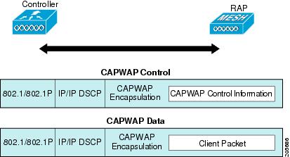
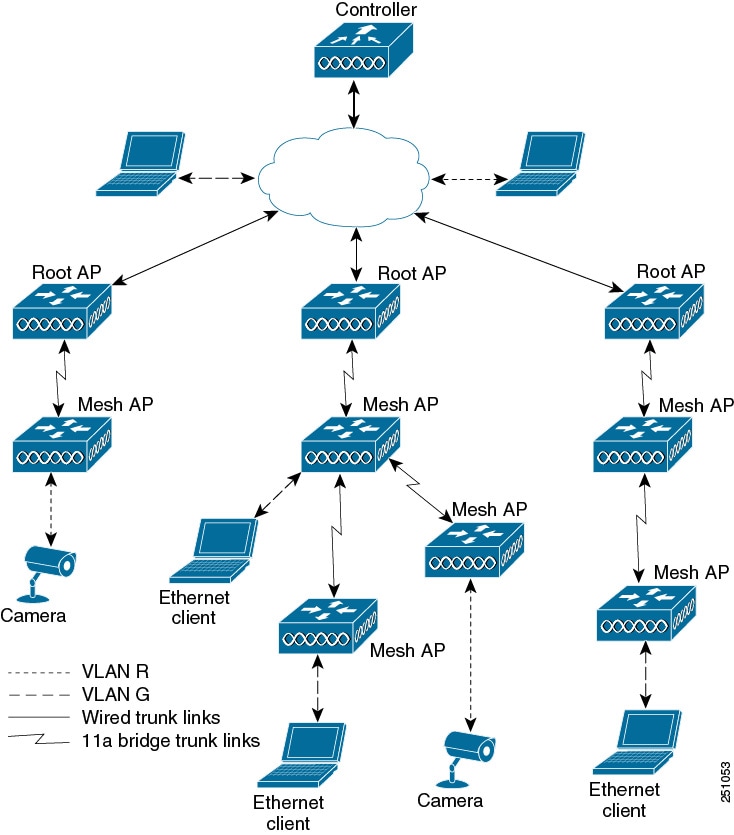
The wireless mesh terminates on two points on the wired network. The first location is where the RAP attaches to the wired network, and where all bridged traffic connects to the wired network. The second location is where the CAPWAP controller connects to the wired network; this location is where the WLAN client traffic from the mesh network connects to the wired network (see Figure 1). The WLAN client traffic from CAPWAP is tunneled at Layer 2, and matching WLANs should terminate on the same switch VLAN where the controllers are collocated. The security and network configuration for each of the WLANs on the mesh depend on the security capabilities of the network to which the controller is connected.
For more information about upgrading to a new controller software release, see the Release Notes for Cisco Wireless LAN Controllers and Lightweight Access Points at http://www.cisco.com/en/US/products/ps10315/prod_release_notes_list.html.
For more information about mesh and controller software releases and the compatible access points, see the Cisco Wireless Solutions Software Compatibility Matrix at http://www.cisco.com/en/US/docs/wireless/controller/5500/tech_notes/Wireless_Software_Compatibility_Matrix.html.
This chapter contains the following sections:
- Adding Mesh Access Points to the Mesh Network
- Mesh PSK Key provisioning in release 8.2
- Configuring Global Mesh Parameters
- Mesh Backhaul at 5 and 2.4 Ghz in Release 8.2
- Backhaul Client Access
- Configuring Local Mesh Parameters
- Configuring Antenna Gain
- Configuring Dynamic Channel Assignment
- Configuring Radio Resource Management on a Bridge Mode Access Point
- Configuring Advanced Features
Adding Mesh Access Points to the Mesh Network
This section assumes that the controller is already active in the network and is operating in Layer 3 mode.
 Note | Controller ports that the mesh access points connect to should be untagged. |
Before adding a mesh access point to a network, do the following:
Adding MAC Addresses of Mesh Access Points to MAC Filter
You must enter the radio MAC address for all mesh access points that you want to use in the mesh network into the appropriate controller. A controller only responds to discovery requests from outdoor radios that appear in its authorization list. MAC filtering is enabled by default on the controller, so only the MAC addresses need to be configured. If the access point has an SSC and has been added to the AP Authorization List, then the MAC address of the AP does not need to be added to the MAC Filtering List.
You can add the mesh access point using either the GUI or the CLI.
Note | You can also download the list of mesh access point MAC addresses and push them to the controller using Cisco Prime Infrastructure. |
Adding the MAC Address of the Mesh Access Point to the Controller Filter List (GUI)
To add a MAC filter entry for the mesh access point on the controller using the controller GUI, follow these steps:
Adding the MAC Address of the Mesh Access Point to the Controller Filter List (CLI)
To add a MAC filter entry for the mesh access point on the controller using the controller CLI, follow these steps:
| Step 1 | To add the MAC address of the mesh access point to the controller filter list, enter this command: config macfilter add ap_mac wlan_id interface [description] A value of zero (0) for the wlan_id parameter specifies any WLAN, and a value of zero (0) for the interface parameter specifies none. You can enter up to 32 characters for the optional description parameter. |
| Step 2 | To save your changes, enter this command: |
Defining Mesh Access Point Role
By default, AP1500s are shipped with a radio role set to MAP. You must reconfigure a mesh access point to act as a RAP.
- General Notes about MAP and RAP Association With The Controller
- Configuring the AP Role (GUI)
- Configuring the AP Role (CLI)
General Notes about MAP and RAP Association With The Controller
The general notes are as follows:
-
A MAP always sets the Ethernet port as the primary backhaul if it is UP, and secondarily the 802.11a/n/ac radio. This gives the network administrator time to reconfigure the mesh access point as a RAP, initially. For faster convergence on the network, we recommend that you do not connect any Ethernet device to the MAP until it has joined the mesh network.
-
A MAP that fails to connect to a controller on a UP Ethernet port, sets the 802.11a/n/ac radio as the primary backhaul. If a MAP fails to find a neighbor or fails to connect to a controller through a neighbor, the Ethernet port is set as the primary backhaul again.
-
A MAP connected to a controller over an Ethernet port does not build a mesh topology (unlike a RAP).
-
A RAP always sets the Ethernet port as the primary backhaul.
-
If the Ethernet port is DOWN on a RAP, or a RAP fails to connect to a controller on a UP Ethernet port, the 802.11a/n/ac radio is set as the primary backhaul for 15 minutes. Failing to find a neighbor or failing to connect to a controller via any neighbor on the 802.11a/n/ac radio causes the primary backhaul to go into the scan state. The primary backhaul begins its scan with the Ethernet port.
Configuring the AP Role (GUI)
To configure the role of a mesh access point using the GUI, follow these steps:
| Step 1 | Click Wireless to open the All APs page. |
| Step 2 | Click the name of an access point. The All APs > Details (General) page appears. |
| Step 3 | Click the
Mesh tab.
|
| Step 4 | Choose RootAP or MeshAP from the AP Role drop-down list. |
| Step 5 | Click Apply to commit your changes and to cause the access point to reboot. |
Configuring the AP Role (CLI)
To configure the role of a mesh access point using the CLI, enter the following command:
Configuring Multiple Controllers Using DHCP 43 and DHCP 60
To configure DHCP Option 43 and 60 for mesh access points in the embedded Cisco IOS DHCP server, follow these steps:
| Step 1 | Enter configuration mode at the Cisco IOS CLI. |
| Step 2 | Create the DHCP pool,
including the necessary parameters such as the default router and name server.
The commands used to create a DHCP pool are as follows:
ip dhcp pool pool name network IP Network Netmask default-router Default router dns-server DNS Server pool name is the name of the DHCP pool, such as AP1520 IP Network is the network IP address where the controller resides, such as 10.0.15.1 Netmask is the subnet mask, such as 255.255.255.0 Default router is the IP address of the default router, such as 10.0.0.1 DNS Server is the IP address of the DNS server, such as 10.0.10.2 |
| Step 3 | Add the option 60 line using
the following syntax:
option 60 ascii “VCI string” For the VCI string, use one of the values below. The quotation marks must be included. For Cisco 1570 series access points, enter “Cisco AP c1570” For Cisco 1560 series access points, enter “Cisco AP c1560” For Cisco 1530 series access points, enter “Cisco AP c1530” For Cisco 1540 series access points, enter “Cisco AP c1540” |
| Step 4 | Add the option 43 line using
the following syntax:
option 43 hex hex string The hex string is assembled by concatenating the TLV values shown below: Type is always f1(hex). Length is the number of controller management IP addresses times 4 in hex. Value is the IP address of the controller listed sequentially in hex. For example, suppose that there are two controllers with management interface IP addresses 10.126.126.2 and 10.127.127.2. The type is f1(hex). The length is 2 * 4 = 8 = 08 (hex). The IP addresses translate to 0a7e7e02 and 0a7f7f02. Assembling the string then yields f1080a7e7e020a7f7f02. The resulting Cisco IOS command added to the DHCP scope is listed below: option 43 hex f1080a7e7e020a7f7f02 |
Backup Controllers
A single controller at a centralized location can act as a backup for mesh access points when they lose connectivity with the primary controller in the local region. Centralized and regional controllers need not be in the same mobility group. Using the controller GUI or CLI, you can specify the IP addresses of the backup controllers, which allows the mesh access points to fail over to controllers outside of the mobility group.
You can also configure primary and secondary backup controllers (which are used if primary, secondary, or tertiary controllers are not specified or are not responsive) for all access points connected to the controller as well as various timers, including the heartbeat timer and discovery request timers.
Note | The fast heartbeat timer is not supported on access points in bridge mode. The fast heartbeat timer is configured only on access points in local and FlexConnect modes. |
The mesh access point maintains a list of backup controllers and periodically sends primary discovery requests to each entry on the list. When the mesh access point receives a new discovery response from a controller, the backup controller list is updated. Any controller that fails to respond to two consecutive primary discovery requests is removed from the list. If the mesh access point’s local controller fails, it chooses an available controller from the backup controller list in this order: primary, secondary, tertiary, primary backup, and secondary backup. The mesh access point waits for a discovery response from the first available controller in the backup list and joins the controller if it receives a response within the time configured for the primary discovery request timer. If the time limit is reached, the mesh access point assumes that the controller cannot be joined and waits for a discovery response from the next available controller in the list.
Note | When a mesh access point’s primary controller comes back online, the mesh access point disassociates from the backup controller and reconnects to its primary controller. The mesh access point falls back to its primary controller and not to any secondary controller for which it is configured. For example, if a mesh access point is configured with primary, secondary, and tertiary controllers, it fails over to the tertiary controller when the primary and secondary controllers become unresponsive and waits for the primary controller to come back online so that it can fall back to the primary controller. The mesh access point does not fall back from the tertiary controller to the secondary controller if the secondary controller comes back online; it stays connected to the tertiary controller until the primary controller comes back up. |
Configuring External Authentication and Authorization Using a RADIUS Server
External authorization and authentication of mesh access points using a RADIUS server such as Cisco ACS (4.1 and later) and ISE are supported in release 7.0 and later releases. The RADIUS server must support the client authentication type of EAP-FAST with certificates.
Before you employ external authentication within the mesh network, ensure that you make these changes:
-
The RADIUS server to be used as an AAA server must be configured on the controller.
-
The controller must also be configured on the RADIUS server.
-
Add the mesh access point configured for external authorization and authentication to the user list of the RADIUS server.
-
Configure EAP-FAST on the RADIUS server and install the certificates. EAP-FAST authentication is required if mesh access points are connected to the controller using an 802.11a interface; the external RADIUS servers need to trust Cisco Root CA 2048. For information about installing and trusting the CA certificates, see the Configuring RADIUS Servers section.
Note
If mesh access points connect to a controller using a Fast Ethernet or Gigabit Ethernet interface, only MAC authorization is required.
Note
This feature also supports local EAP and PSK authentication on the controller.
Configuring RADIUS Servers
To install and trust the CA certificates on the RADIUS server, follow these steps:
| Step 1 | Download the CA certificates for Cisco Root CA 2048 from the following locations: |
| Step 2 | Install the certificates as follows: |
| Step 3 | Configure the external RADIUS servers to trust the CA certificate as follows:
|
For additional configuration details on Cisco ACS servers, see the following:
Enabling External Authentication of Mesh Access Points (GUI)
To enable external authentication for a mesh access point using the GUI, follow these steps:
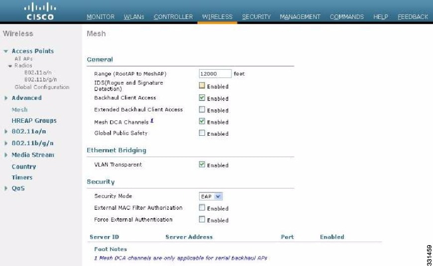
| Step 1 | Choose
Wireless
> Mesh. The Mesh page appears (see
Figure 1).
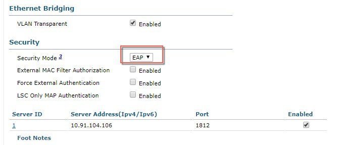 |
| Step 2 | In the security section, select the EAP option from the Security Mode drop-down list. |
| Step 3 | Select the Enabled check boxes for the External MAC Filter Authorization and Force External Authentication options. |
| Step 4 | Click Apply. |
| Step 5 | Click Save Configuration. |
Adding a Username to a RADIUS Server
Add MAC addresses of mesh access point that are authorized and authenticated by external RADIUS servers to the user list of that server prior to enabling RADIUS authentication for a mesh access point.
For remote authorization and authentication, EAP-FAST uses the manufacturer’s certificate (CERT) to authenticate the child mesh access point. Additionally, this manufacturer certificate-based identity serves as the username for the mesh access point in user validation.
For Cisco IOS-based mesh access points, in addition to adding the MAC address to the user list, you need to enter the platform_name_string–MAC_address string to the user list (for example, c1240-001122334455). The controller first sends the MAC address as the username; if this first attempt fails, then the controller sends the platform_name_string–MAC_address string as the username.
Note | The Authentication MAC address is different for outdoor versus indoor APs. Outdoor APs use the AP's BVI MAC address, whereas indoor APs use the AP's Gigabit Ethernet MAC address. |
RADIUS Server Username Entry
Note | The AP1552 platform uses a platform name of c1550. The AP1572 uses a platform name of c1570. |
Enable External Authentication of Mesh Access Points (CLI)
To enable external authentication for mesh access points using the CLI, enter the following commands:
View Security Statistics (CLI)
To view security statistics for mesh access points using the CLI, enter the following command:
show mesh security-stats Cisco_AP
Use this command to display packet error statistics and a count of failures, timeouts, and association and authentication successes as well as reassociations and reauthentications for the specified access point and its child.
Mesh PSK Key provisioning in release 8.2
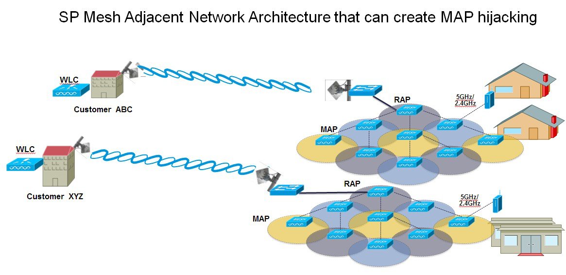
Customers with Cisco
Mesh deployment will see their Mesh Access Points (MAP) possibly moving out of
their network and joining another Mesh network when both of these Mesh
Deployments use AAA with wild card MAC filtering to allow MAPs association. As
Mesh APs security may use EAP-FAST this cannot be controlled since for EAP
security combination of MAC address and type of AP is used and there is no
controlled configuration is available. PSK option with default passphrase also
presents security risk and hijack possibility. This issue will be prominently
seen in overlapping deployments of two different SPs when the MAPs are used in
a moving vehicle (public transportations, ferry, ship and so on.). This way,
there is no restriction on MAPs to 'stick' to the SPs mesh network and MAPs can
be hijacked / getting used by another SPs network / and cannot serve intended
customers of SPs in a deployment.
The new feature introduced in 8.2 release will enable a provision-able PSK functionality from WLC which will help make a controlled mesh deployment and enhance MAPs security beyond default 'cisco' PSK used today. With this new feature the MAPs which are configured with a custom PSK, will use this key to do their authentication with their RAPs and WLC. A special precaution should be taken when upgrading from Controller Software release 8.1 and below or downgrading from release 8.2. Admin needs to understand the implications when MAP software is moving in and out of PSK support.
- Wireless Mesh Components Supported
- Feature Configuration Step-by-Step
- CLI Commands for PSK Provisioning
Wireless Mesh Components Supported
Feature Configuration Step-by-Step
Admin shall set security mode as PSK and optionally configure a new PSK. If there is no PSK configured MAPs will be able to join with default PSK key ‘cisco’.
-
Provisioning shall be local to each WLC
-
Need to be in 'enabled' state to allow local provisioning
-
Key strength as followed in WLC (Alphanumeric with special characters combination of lower, upper case, length 3-32 characters, special characters supported, redundant passwords not supported.
-
Provisioned PSK is encrypted at WLC, stored, and sent to APs in encrypted format.
Mesh PSK GUI Configuration
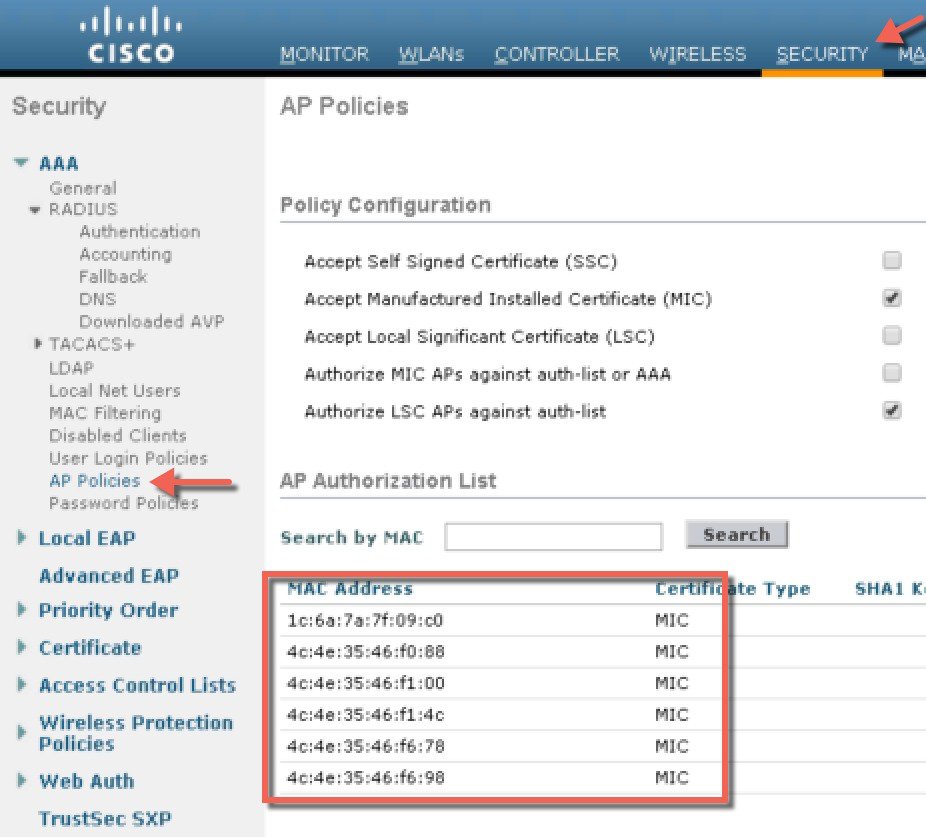
| Step 1 | Connect a RAP
to the controller as documented in the above sections of this Deployment Guide.
As shown in the Configuration illustration example below two 1532 MAPs are
connected to the RAP 1572.
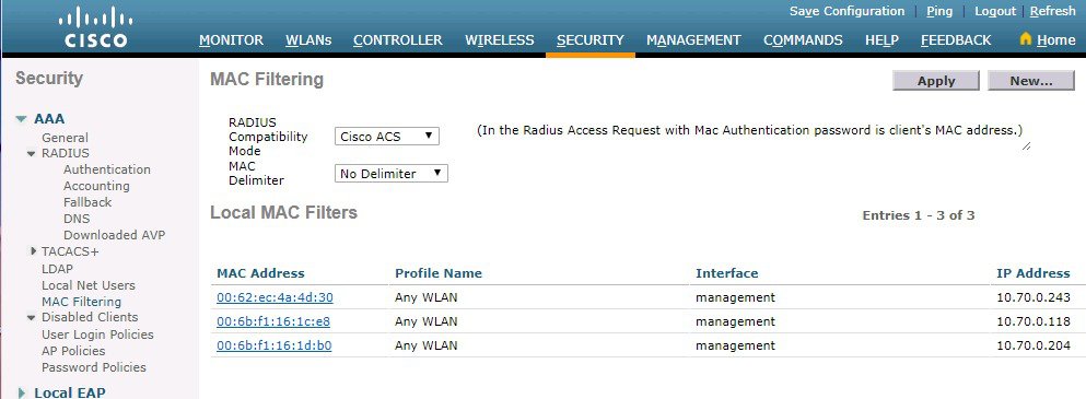
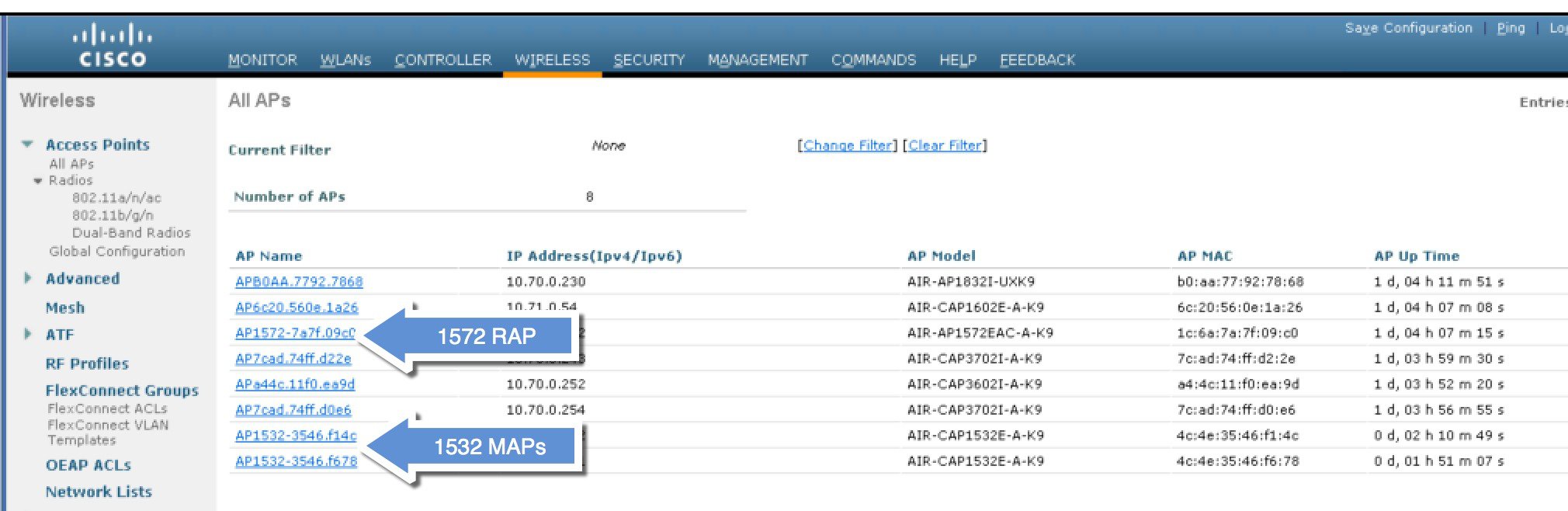 As
indicated in the deployment guide one of the options for the MAPs initial
connection the MAP MAC addresses have to be entered on the controller for them
to be connected to the RAP as indicated in the screen shot.
| ||||
| Step 2 | From Wireless
> Mesh menu, choose Security Mode as PSK and enable PSK provisioning.
Prior to release 8.2 MAC, AAA authentication with wild card character or EAP authentication were the only three methods where EAP was basically used with default internal authentication and MAC address provisioning was not reliable enough in certain installations especially when Mesh installations from different customers were overlapping and there was a strong probability of Mesh APs being accidently hijacked from one Mesh network to another. That could create many issues and coverage holes in the Mesh deployments. For that reason in release 8.2 a PSK MAP provisioning was introduced. As indicated above the PSK key has to be created on the wireless controller. 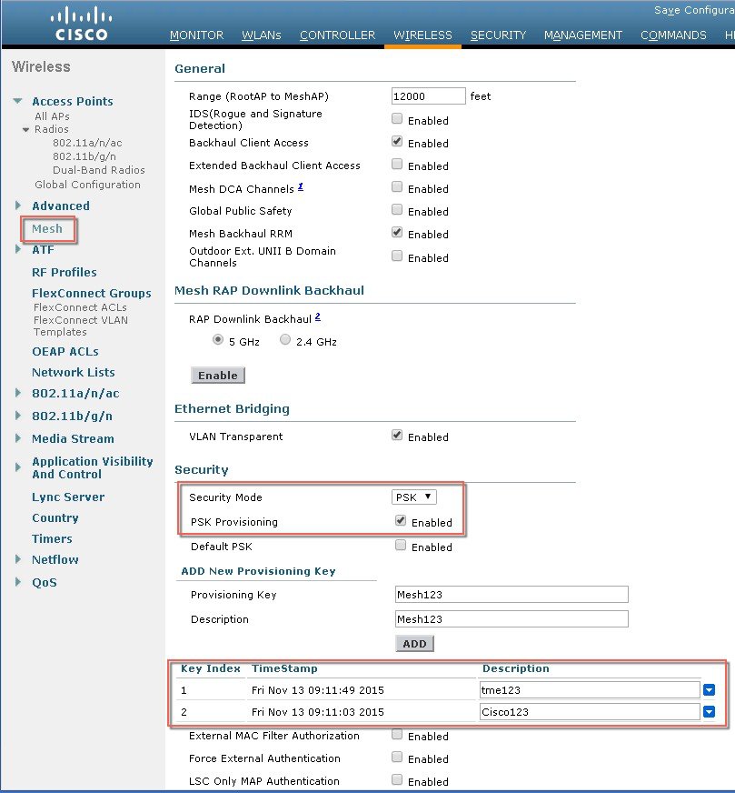
| ||||
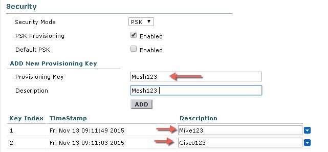
| Step 3 | Enter
Provisioning Key as shown in the example and hit ADD to apply the entered
value.
The Key value will not show in the list but only the Index of the key with a time stamp when that key was provisioned on the controller. Up to 5 keys can be entered on the controller for MAPs to be used for provisioning. Any of those 5 keys that are always stored in flash on the controller, can be used by MAP for provisioning. MD5 cryptographic algorithm (128-bit) is used to encrypt a provisioned PSK and sent down to APs during new key configuration.
| ||||
| Step 4 | Once the
controller has the PSK key configured and enabled the key will be provisioned
on the RAP and propagated to all MAPs connected to that RAP. The same key will
be also propagated to all other children MAPs in the mesh network. There is no
need to do anything on the MAPs in order for them to receive PSK key and
authenticate to the RAP/MAP network
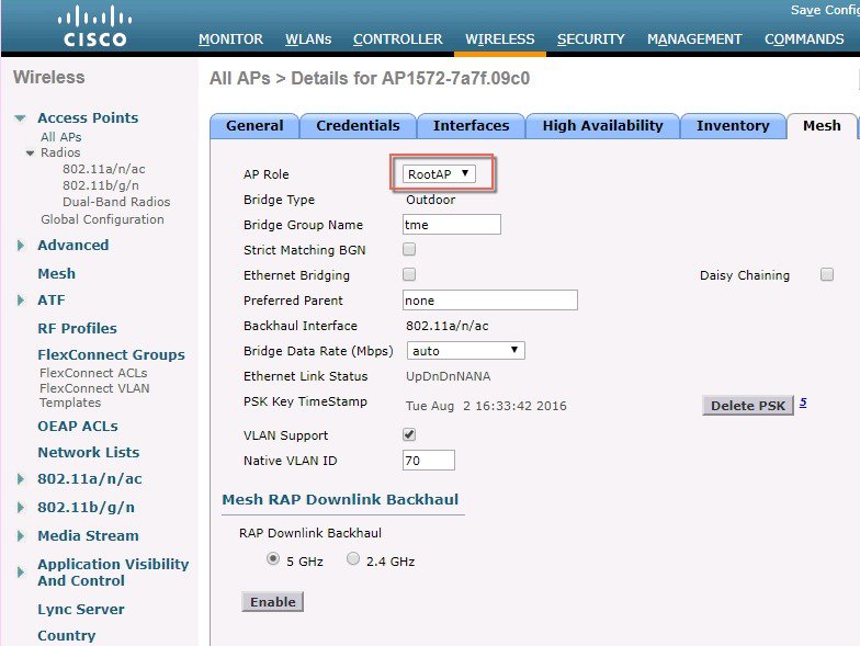
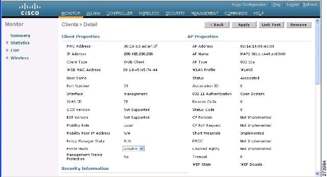
As shown in the example when observing one specific MAP that connected to the RAP, under the Mesh tab - you can see that MAP has been provisioned using PSK key with index 1 and Time Stamp from August 19th. 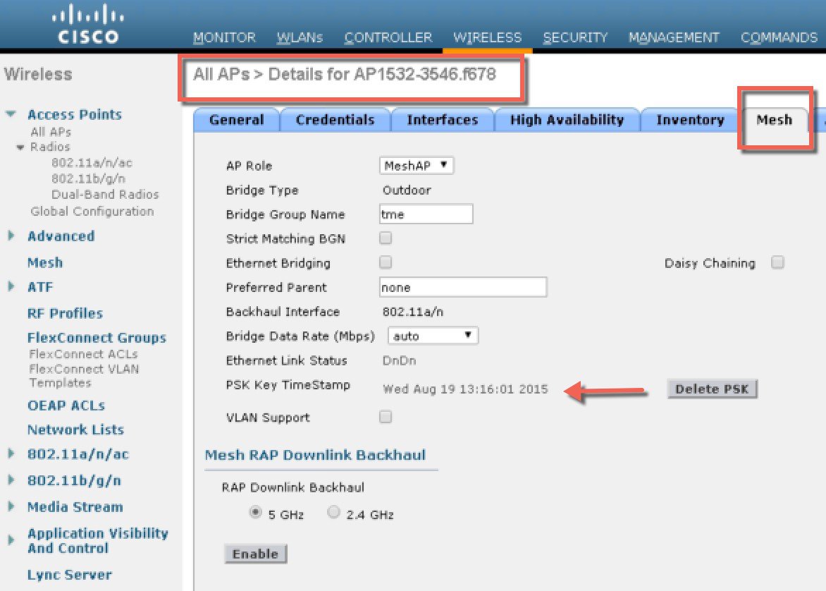
| ||||
| Step 5 | The
provisioned PSK key can be deleted from MAP or RAP in case PSK key was
compromised or deleted on the controller intentionally.
| ||||
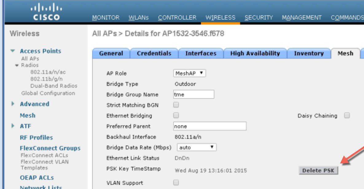
| Step 6 | If MAP
accidently connected to the wrong network and obtained Key from there, admin
has an option to delete that wrong PSK key. In addition, "Delete PSK" for PSK
timestamp in WLC GUI interface can be used to remove a provisioned PSK of AP
when it joined via EAP security. This option is sort of Mesh AP recovery option
when AP has been stranded with staled or not valid PSK and EAP security was
used to rejoin a stranded Mesh AP. When PSK key is deleted from the MAP, it
will go back to using its default PSK key "cisco".
However, note that if the PSK key is still configured on the controller and in turn on the RAP/MAP, then the MAP without a matching PSK key will not be able to connect to the Mesh network. For un-provisioned MAP to connect to the PSK enabled mesh network on the controller the Provisioning Window has to be enabled. As shown in the example when Provisioning Window is manually enabled the MAP will be allowed to connect using default "cisco" PSK key and at the same time obtain new PSK key. 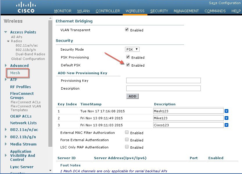
|
Mesh PSK Provisioning with Controllers In Mobility Group
In case there is a configuration of RAPs in the Mobility Group it is always advised to use the same PSK Keys or one of the 5 allowable PSK keys on all controllers in the Mobility Group; this way when MAPs coming from a different controllers they will be able to authenticate. By looking at the time stamp of the PSK you can find out where the MAP and PSK Key came from.
-
All Controllers should have the same PSKs. WLCs with different keys will result in unexpected behavior if RAPs and MAPs move between them, and may even cause extended outages.
-
All controllers should be set for the same security method – mixed EAP and PSK (with provisioning enabled and PSK(s) created) is not recommended..
All controllers should be set for the same security method – mixed EAP and PSK (with provisioning enabled and PSK(s) created) is not recommended
CLI Commands for PSK Provisioning
Configuring Global Mesh Parameters
This section provides instructions to configure the mesh access point to establish a connection with the controller including:
Setting the maximum range between RAP and MAP (not applicable to indoor MAPs).
Defining the authentication mode (EAP or PSK) and method (local or external) for mesh access points including security settings (local and external authentication).
You can configure the necessary mesh parameters using either the GUI or the CLI. All parameters are applied globally.
Configuring Global Mesh Parameters (GUI)
To configure global mesh parameters using the controller GUI, follow these steps:
| Step 1 | Choose Wireless > Mesh. | ||||||||||||||||||||||||||||||||||||||||||
| Step 2 | Modify the mesh parameters as
appropriate.
| ||||||||||||||||||||||||||||||||||||||||||
| Step 3 | Click Apply. | ||||||||||||||||||||||||||||||||||||||||||
| Step 4 | Click Save Configuration. |
Configuring Global Mesh Parameters (CLI)
To configure global mesh parameters including authentication methods using the controller CLI, follow these steps:
Note | See the Configuring Global Mesh Parameters (GUI) section for descriptions, valid ranges, and default values of the parameters used in the CLI commands. |
| Step 1 | To specify the maximum range (in feet) of all mesh access points in the network, enter this command:
To see the current range, enter the show mesh range command. |
| Step 2 | To enable or disable IDS reports for all traffic on the backhaul, enter this command: |
| Step 3 | To specify the rate (in Mbps) at which data is shared between access points on the backhaul interface, enter this command: |
| Step 4 | To enable or disable client association on the primary backhaul (802.11a) of a mesh access point, enter these commands: config mesh client-access {enable | disable} |
| Step 5 | To enable or disable VLAN transparent, enter this command: config mesh ethernet-bridging VLAN-transparent {enable | disable} |
| Step 6 | To define a security mode for the mesh access point, enter one of the following commands: |
| Step 7 | To save your changes, enter this command: |
Viewing Global Mesh Parameter Settings (CLI)
Use these commands to obtain information on global mesh settings:
-
show mesh client-access—When Backhaul Client Access is enabled, it allows wireless client association over the backhaul radio. Generally, backhaul radio is a 5-GHz radio for most of the mesh access points. This means that a backhaul radio can carry both backhaul traffic and client traffic.
When Backhaul Client Access is disabled, only backhaul traffic is sent over the backhaul radio and client association is only over the second radio(s).
(Cisco Controller)> show mesh client-access
Backhaul with client access status: enabled
-
show mesh ids-state—Shows the status of the IDS reports on the backhaul as either enabled or disabled.
(Cisco Controller)> show mesh ids-state
Outdoor Mesh IDS(Rogue/Signature Detect): .... Disabled
-
show mesh config—Displays global configuration settings.
(Cisco Controller)> show mesh config
Mesh Range....................................... 12000
Mesh Statistics update period.................... 3 minutes
Backhaul with client access status............... disabled
Background Scanning State........................ enabled
Backhaul Amsdu State............................. disabled

Mesh Security
Security Mode................................. EAP
External-Auth................................. disabled
Use MAC Filter in External AAA server......... disabled
Force External Authentication................. disabled

Mesh Alarm Criteria
Max Hop Count................................. 4
Recommended Max Children for MAP.............. 10
Recommended Max Children for RAP.............. 20
Low Link SNR.................................. 12
High Link SNR................................. 60
Max Association Number........................ 10
Association Interval.......................... 60 minutes
Parent Change Numbers......................... 3
Parent Change Interval........................ 60 minutes

Mesh Multicast Mode.............................. In-Out
Mesh Full Sector DFS............................. enabled

Mesh Ethernet Bridging VLAN Transparent Mode..... enabled
Mesh Backhaul at 5 and 2.4 Ghz in Release 8.2
Prior to release 8.2 Wireless Mesh Backhaul was supported only at 5GHz. In release 8.2 Wireless Mesh backhaul is supported at 5 and 2.4 GHz.
In certain countries it is not allowed to use Mesh Network with 5 Ghz backhaul network or even in the courtiers when 5Ghz is permitted customer may prefer to use 2.4 Ghz radio frequencies to achieve much larger Mesh or Bridge distances.
When a RAP gets change of the configuration from 5 to 2.4 Ghz that selection gets propagated from RAP to all MAPs and they will disconnect from 5Ghz network and get reconnected at 2.4 Ghz. Please note if configuring 2.4Ghz make sure all Controllers are configured with version 8.2 so that 2.4 Ghz backhaul is recognized.
Note | Only RAPs are
configured with the backhaul frequency of 5 or 2.4GHz. Once RAP is configured
that frequency selection will propagate down the branch to all MAPs.
|

| Step 1 | To configure
Mesh Backhaul to 2.4 Ghz one simple step is required on the controller. As
illustrated configure the RAP Downlink Backhaul to 2.4 Ghz and hit Enable.
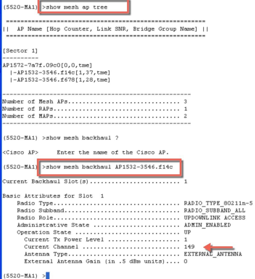
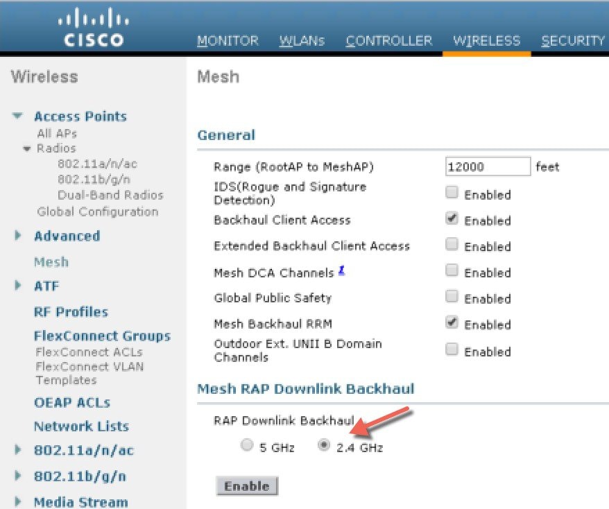 From the CLI
you can issue "show mesh ap tree" and "show mesh backhaul <ap-name> to
see the backhaul connection.
| ||
| Step 2 | On the RAP the
channel has to be changed to 2.4GHz and channel has to be custom selected and
that selection will be propagated to all MAPs and "children" in the Branch of
that RAP.
After Channel is selected under the Custom option that channel will be used for the RAP Backhaul.
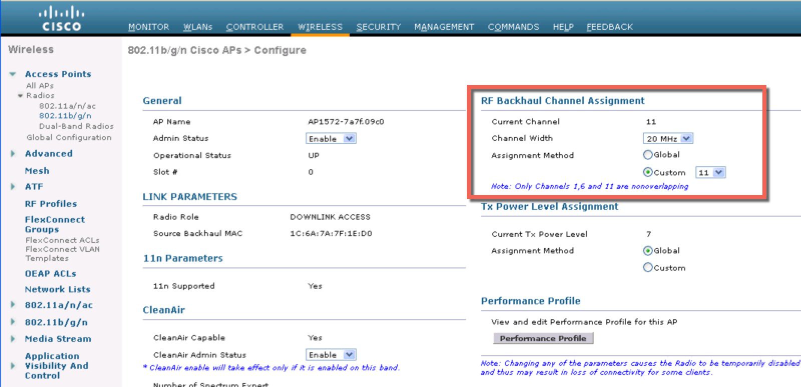
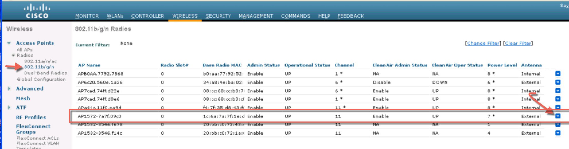
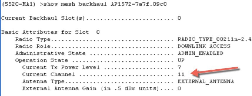
After the Channel change on the RAP as illustrated in the example below, the channel on the MAP has changed to CH11 in 2.4 GHz band. Example of the
MAP CLI command: show mesh backhaul <ap-name>
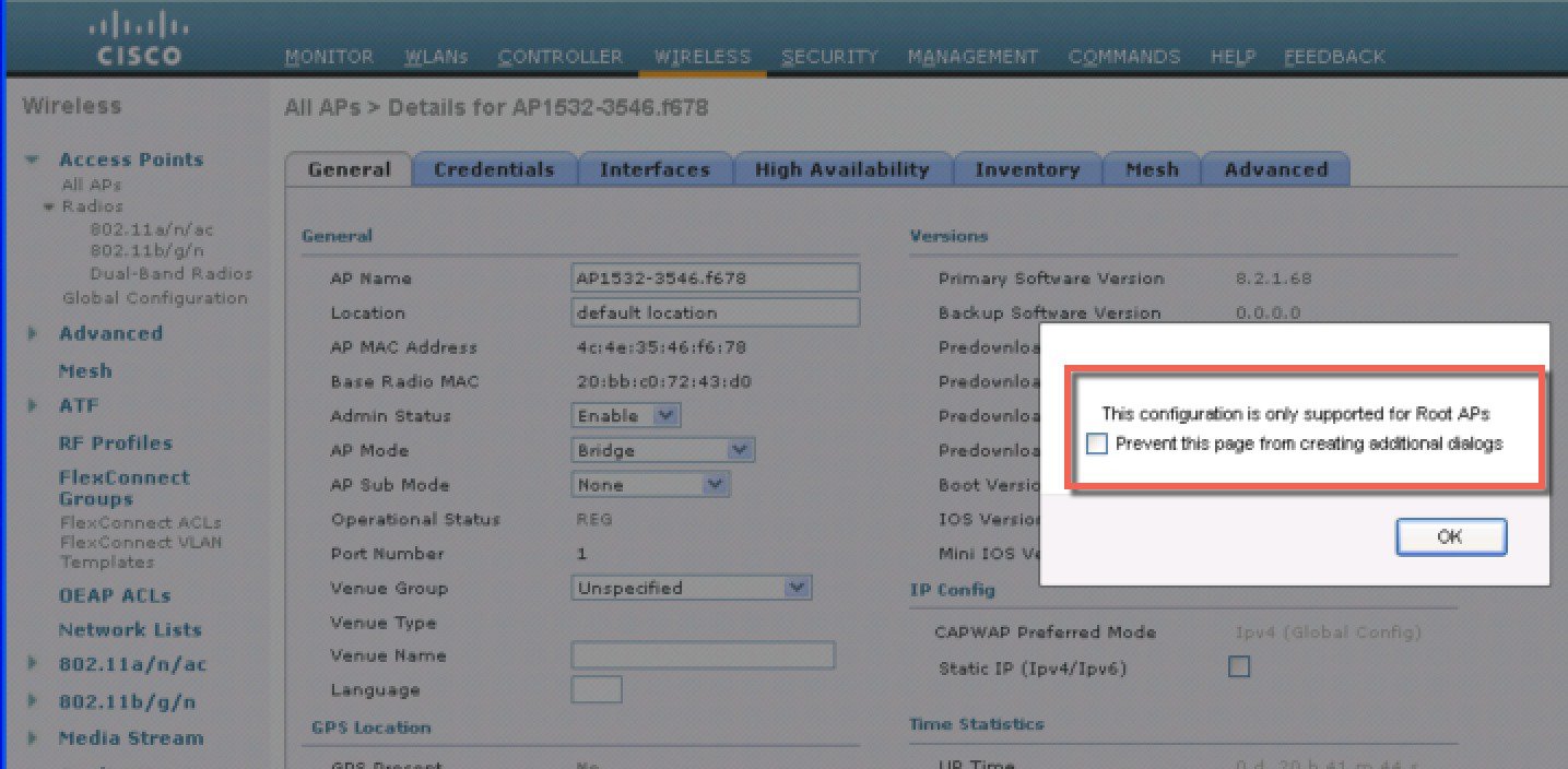
If for example
you would try to change the Backhaul channel on the MAP you will get an error
message since this functionality is not supported on the MAPs. MAPs and “map
children” receive their Channel assignments from the upstream parent RAP. An
example of the error message from the MAP is as shown.
|
Backhaul Client Access
When Backhaul Client Access is enabled, it allows wireless client association over the backhaul radio. The backhaul radio is a 5 GHz radio. This means that a backhaul radio can carry both backhaul traffic and client traffic.
When Backhaul Client Access is disabled, only backhaul traffic is sent over the backhaul radio and client association is only over the second radio(s).
Note | Backhaul Client Access is disabled by default. After this feature is enabled, all mesh access points, except slave AP and its child APs in Daisy-chained deployment, reboot. |
This feature is applicable to mesh access points with two radios (1552, 1532, 1540, 1560, 1572, and Indoor APs in Bridge mode).
Configuring Backhaul Client Access (GUI)
This figure shows how to enable Backhaul Client Access using the GUI. You will be prompted that the AP will reboot if you enable Backhaul Client Access.
Configuring Backhaul Client Access (CLI)
Use the following command to enable Backhaul Client Access:
(Cisco Controller)> config mesh client-access enable
The following message is displayed:
All Mesh APs will be rebooted
Are you sure you want to start? (y/N)
Configuring Local Mesh Parameters
After configuring global mesh parameters, you must configure the following local mesh parameters for these specific features if in use in your network:
-
Backhaul Data Rate. See the Configuring Wireless Backhaul Data Rate section.
-
Ethernet Bridging. See the Configuring Ethernet Bridging section.
-
Bridge Group Name. See theConfiguring Ethernet Bridging section.
-
Workgroup Bridge. See the Configuring Workgroup Bridges section.
-
Power and Channel Setting. See theConfiguring Power and Channel Settings section.
-
Antenna Gain Settings. See the Configuring Antenna Gain section.
-
Dynamic Channel Assignment. See the Configuring Dynamic Channel Assignment section.
Configuring Wireless Backhaul Data Rate
Backhaul is used to create only the wireless connection between the access points. The backhaul interface vary between 802.11a/n/ac rates depending upon the access point. The rate selection is important for effective use of the available RF spectrum. The rate can also affect the throughput of client devices, and throughput is an important metric used by industry publications to evaluate vendor devices.
Dynamic Rate Adaptation (DRA) introduces a process to estimate optimal transmission rate for packet transmissions. It is important to select rates correctly. If the rate is too high, packet transmissions fail resulting in communication failure. If the rate is too low, the available channel bandwidth is not used, resulting in inferior products, and the potential for catastrophic network congestion and collapse.
Data rates also affect the RF coverage and network performance. Lower data rates, for example 6 Mbps, can extend farther from the access point than can higher data rates, for example 1300 Mbps. As a result, the data rate affects cell coverage and consequently the number of access points required. Different data rates are achieved by sending a more redundant signal on the wireless link, allowing data to be easily recovered from noise. The number of symbols sent out for a packet at the 1-Mbps data rate is higher than the number of symbols used for the same packet at 11 Mbps. Therefore, sending data at the lower bit rates takes more time than sending the equivalent data at a higher bit rate, resulting in reduced throughput.
In the controller release 5.2, the default data rate for the mesh 5-GHz backhaul is 24 Mbps. It remains the same with 6.0 and 7.0 controller releases.
With the 6.0 controller release, mesh backhaul can be configured for ‘Auto’ data rate. Once configured, the access point picks the highest rate where the next higher rate cannot be used because of conditions not being suitable for that rate and not because of conditions that affect all rates. That is, once configured, each link is free to settle down to the best possible rate for its link quality.
We recommend that you configure the mesh backhaul to Auto.
For example, if mesh backhaul chose 48 Mbps, then this decision is taken after ensuring that we cannot use 54 Mbps as there is not enough SNR for 54 and not because some just turned the microwave oven on which affects all rates.
A lower bit rate might allow a greater distance between MAPs, but there are likely to be gaps in the WLAN client coverage, and the capacity of the backhaul network is reduced. An increased bit rate for the backhaul network either requires more MAPs or results in a reduced SNR between MAPs, limiting mesh reliability and interconnection.
This figure shows the RAP using the "auto" backhaul data rate, and it is currently using 54 Mbps with its child MAP.
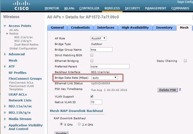
Note | The data rate can be set on the backhaul on a per-AP basis. It is not a global command. |
Related Commands
Use these commands to obtain information about backhaul:
-
config ap bhrate—Configures the Cisco Bridge backhaul Tx rate.
(controller) > config ap bhrate backhaul-rate ap-name
Note
Preconfigured data rates for each AP (RAP=18 Mbps, MAP1=36 Mbps) are preserved after the upgrade to 6.0 or later software releases.??Before you upgrade to the 6.0 release, if you have the backhaul data rate configured to any data rate, then the configuration is preserved.
The following example shows how to configure a backhaul rate of 36000 Kbps on a RAP:
(controller) > config ap bhrate 36000 HPRAP1
-
show ap bhrate—Displays the Cisco Bridge backhaul rate.
(controller) > show ap bhrate ap-name
-
show mesh neigh summary—Displays the link rate summary including the current rate being used in backhaul
(controller) > show mesh neigh summary HPRAP1

AP Name/Radio    Channel     Rate     Link-Snr     Flags      State
--------------- --------   --------   -------     -----       -----
00:0B:85:5C:B9:20 0          auto        4       0x10e8fcb8   BEACON
00:0B:85:5F:FF:60 0          auto        4       0x10e8fcb8   BEACON DEFAULT
00:0B:85:62:1E:00 165        auto        4       0x10e8fcb8   BEACON
OO:0B:85:70:8C:A0 0          auto        1       0x10e8fcb8   BEACON
HPMAP1           165         54          40      0x36         CHILD BEACON
HJMAP2           0          auto         4       0x10e8fcb8   BEACON
Backhaul capacity and throughput depends upon the type of the AP, that is, if it is 802.11a/n or only 802.11a, number of backhaul radios it has, and so on.
Configuring Ethernet Bridging
For security reasons, the Ethernet port on all MAPs is disabled by default. It can be enabled only by configuring Ethernet bridging on the root and its respective MAP.
Note | Enable Spanning Tree Protocol (STP) on all connected switch ports to avoid Layer 2 looping. |
Ethernet bridging has to be enabled for two scenarios:
-
When you want to use the mesh nodes as bridges (see Figure 1).
Note
You do not need to configure VLAN tagging to use Ethernet bridging for point-to-point and point-to-multipoint bridging deployments.
-
When you want to connect any Ethernet device such as a video camera on the MAP using its Ethernet port. This is the first step to enable VLAN tagging.
Figure 7. Point-to-Multipoint Bridging 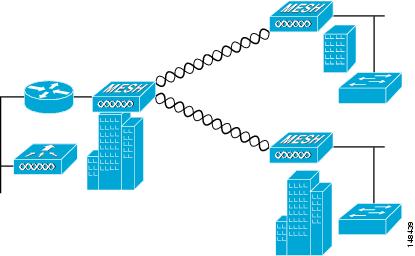
Enabling Ethernet Bridging (GUI)
To enable Ethernet bridging on a RAP or MAP using the GUI, follow these steps:
| Step 1 | Choose Wireless > All APs. |
| Step 2 | Click the AP name link of the mesh access point on which you want to enable Ethernet bridging. |
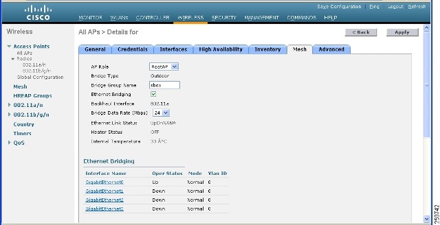
| Step 3 | At the details page, select the Mesh tab (see Figure 1). |
| Step 4 | Select either RootAP or MeshAP from the AP Role drop-down list, if not already selected. |
| Step 5 | Select the Ethernet Bridging check box to enable Ethernet bridging or deselect it to disable this feature. |
| Step 6 | Click Apply to commit your changes. An Ethernet Bridging section appears at the bottom of the page listing each of the Ethernet ports of the mesh access point. |
| Step 7 | Ensure that you enable Ethernet bridging for every parent mesh AP taking the path from the mesh AP in question to the controller. For example, if you enable Ethernet bridging on MAP2 in Hop 2, then you must also enable Ethernet bridging on MAP1 (parent MAP), and on the RAP connecting to the controller. |
Configuring Native VLAN (GUI)
Note | Prior to 8.0, the Native VLAN on the wired backhaul was set as VLAN 1. Starting with the 8.0 release, the Native VLAN can be set. |
| Step 1 | Choose Wireless > All APs. | ||
| Step 2 | Choose the mesh access point on which you would like to configure the Native VLAN. | ||
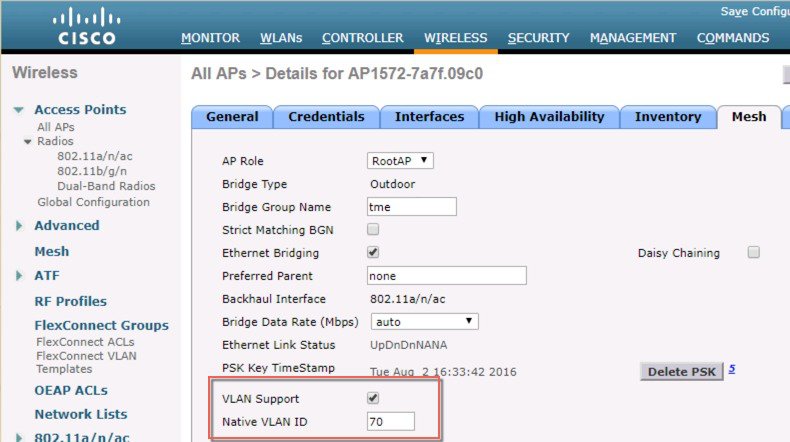
| Step 3 | Check the
VLAN Support
checkbox on the AP.
| ||
| Step 4 | Assign a Native
VLAN.
| ||
| Step 5 | Click Apply to commit your changes. |
Configuring Native VLAN (CLI)
Note | Prior to 8.0, the Native VLAN on the wired backhaul was set as VLAN 1. Starting with the 8.0 release, the Native VLAN can be set. |
Configuring Bridge Group Names
Bridge group names (BGNs) control the association of mesh access points. BGNs can logically group radios to avoid two networks on the same channel from communicating with each other. The setting is also useful if you have more than one RAP in your network in the same sector (area). BGN is a string of 10 characters maximum.
A BGN of NULL VALUE is assigned by default by manufacturing. Although not visible to you, it allows a mesh access point to join the network prior to your assignment of your network-specific BGN.
If you have two RAPs in your network in the same sector (for more capacity), we recommend that you configure the two RAPs with the same BGN, but on different channels.
Configuring Bridge Group Names (CLI)
| Step 1 | To set a bridge group name (BGN), enter this command: config ap bridgegroupname set group-name ap-name
| ||||
| Step 2 | To verify the BGN, enter the following command: |
Verifying Bridge Group Names (GUI)
Configuring Power and Channel Settings
The backhaul channel (802.11a/n) can be configured on a RAP. MAPs tune to the RAP channel. The local access can be configured independently for MAP.
Configuring Power and Channel Settings (GUI)
| Step 1 | Choose
Wireless
> Access Points > 802.11a/n.
| ||
| Step 2 | Select configure from the Antenna drop-down list for the 802.11a/n radio. The Configure page is displayed. | ||
| Step 3 | Assign a channel (assignment methods of global and custom) for the radio. | ||
| Step 4 | Assign Tx power levels
(global and custom) for the radio.
There are five selectable power levels for the 802.11a backhaul for AP1500s.
| ||
| Step 5 | Click Apply when power and channel assignment are complete. | ||
| Step 6 | From the 802.11a/n Radios page, verify that channel assignments were made correctly. |
Configuring Antenna Gain
You must configure the antenna gain for the mesh access point to match that of the antenna installed using the controller GUI or controller CLI.
Configuring Antenna Gain (GUI)
To configure antenna parameters using the controller GUI, follow these steps:
| Step 1 | Choose Wireless > Access Points > Radio > 802.11a/n to open the 802.11a/n Radios page. | ||
| Step 2 | For the mesh access point antenna you want to configure, hover the mouse over the blue arrow (far right) to display antenna options. Choose Configure.
| ||
| Step 3 | In the Antenna Parameters section, enter the antenna gain. The gain is entered in 0.5 dBm units. For example, 2.5 dBm = 5.
| ||
| Step 4 | Click Apply and then Save Configuration to save the changes. |
Configuring Antenna Gain (CLI)
Enter this command to configure the antenna gain for the 802.11a backhaul radio using the controller CLI:
config 802.11a antenna extAntGain antenna_gain AP_name
where gain is entered in 0.5-dBm units (for example, 2.5 dBm =5).
Configuring Dynamic Channel Assignment
Using the controller GUI, follow these steps to specify the channels that the dynamic channel assignment (DCA) algorithm considers when selecting the channels to be used for RRM scanning. This functionality is helpful when you know that the clients do not support certain channels because they are legacy devices or they have certain regulatory restrictions.
The steps outlined in this section are only relevant to mesh networks.
| Step 1 | To disable the 802.11a/n or 802.11b/g/n network, follow these steps: | ||||||||||||
| Step 2 | Choose Wireless > 802.11a/n or 802.11b/g/n > RRM > DCA to open the 802.11a (or 802.11b/g) > RRM > Dynamic Channel Assignment (DCA) page. | ||||||||||||
| Step 3 | Choose one of the following
options from the Channel Assignment Method drop-down list to specify the
controller’s DCA mode:
| ||||||||||||
| Step 4 | From the Interval drop-down list, choose one of the following options to specify how often the DCA algorithm is allowed to run: 10 minutes, 1 hour, 2 hours, 3 hours, 4 hours, 6 hours, 8 hours, 12 hours, or 24 hours. The default value is 10 minutes. | ||||||||||||
| Step 5 | From the AnchorTime drop-down list, choose a number to specify the time of day when the DCA algorithm is to start. The options are numbers between 0 and 23 (inclusive) representing the hour of the day from 12:00 a.m. to 11:00 p.m. | ||||||||||||
| Step 6 | Select the Avoid Foreign AP Interference check box to cause the controller’s RRM algorithms to consider 802.11 traffic from foreign access points (those access points not included in your wireless network) when assigning channels to lightweight access points, or deselect it to disable this feature. For example, RRM may adjust the channel assignment to have access points avoid channels close to foreign access points. The default value is checked. | ||||||||||||
| Step 7 | Select the Avoid Cisco AP Load check box to cause the controller’s RRM algorithms to consider 802.11 traffic from Cisco lightweight access points in your wireless network when assigning channels, or deselect it to disable this feature. For example, RRM can assign better reuse patterns to access points that carry a heavier traffic load. The default value is deselected. | ||||||||||||
| Step 8 | Select the Avoid Non-802.11a (802.11b) Noise check box to cause the controller’s RRM algorithms to consider noise (non-802.11 traffic) in the channel when assigning channels to lightweight access points, or deselect it to disable this feature. For example, RRM may have access points avoid channels with significant interference from nonaccess point sources, such as microwave ovens. The default value is checked. | ||||||||||||
| Step 9 | From the DCA
Channel Sensitivity drop-down list, choose one of the following options to
specify how sensitive the DCA algorithm is to environmental changes such as
signal, load, noise, and interference when determining whether to change
channels:
| ||||||||||||
| Step 10 | For 802.11a/n
networks only, choose one of the following Channel Width options to specify the
channel bandwidth supported for all 802.11 n/a/ac radios in the 5-GHz band:
| ||||||||||||
| Step 11 | In the DCA
Channel List section, the DCA Channels field shows the channels that are
currently selected. To choose a channel, select its check box in the Select
column. To exclude a channel, deselect its check box.
Range: 802.11a—36, 40, 44, 48, 52, 56, 60, 64, 100, 104, 108, 112, 116, 132, 136, 140, 149, 153, 157, 161, 165, 190, 196?802.11b/g—1, 2, 3, 4, 5, 6, 7, 8, 9, 10, 11 Default: 802.11a—36, 40, 44, 48, 52, 56, 60, 64, 100, 104, 108, 112, 116, 132, 136, 140, 149, 153, 157, 161?802.11b/g—1, 6, 11
| ||||||||||||
| Step 12 | If you are
using AP1500s in your network, you must set the 4.9-GHz channels in the 802.11a
band on which they are to operate. The 4.9-GHz band is for public safety client
access traffic only. To choose a 4.9-GHz channel, select its check box in the
Select column. To exclude a channel, deselect its check box.
Range: ?802.11a—1, 2, 3, 4, 5, 6, 7, 8, 9, 10, 11, 12, 13, 14, 15, 16, 17, 18, 19, 20, 21, 22, 23, 24, 25, 26 | ||||||||||||
| Step 13 | Click Apply to commit your changes. | ||||||||||||
| Step 14 | To reenable the 802.11a or 802.11b/g network, follow these steps: | ||||||||||||
| Step 15 | Click
Save
Configuration to save your changes.
|
Configuring Radio Resource Management on a Bridge Mode Access Point
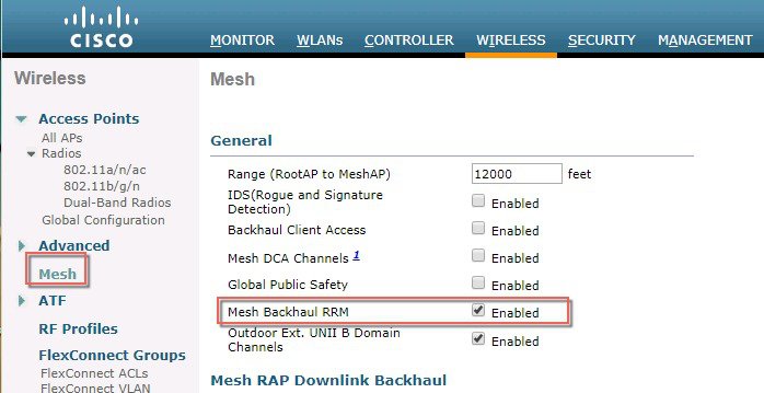
Radio Resource Management (RRM) can be enabled on the backhaul radio of a bridge mode access point if:
-
AP is a root AP (RAP)
-
RAP has a wired Ethernet link to a WLC
-
RAP has no child Mesh APs connected to it
Once these conditions are met, full RRM will be established, including transmit power control (TPC), Dynamic Channel Assignment (DCA), and Coverage Hole Detection and Mitigation (CHDM). If a Mesh AP needs to re-join a RAP participating in RRM, the RAP will immediately stop all RRM functionality.
-
config mesh backhaul rrm <enable|disable> — To enable RRM on the mesh backhaul radio
-
Config mesh backhaul rrm <auto-rf global|off> — To enable/disable dynamic channel assignment only
Configuring Advanced Features
- Configuring Ethernet VLAN Tagging
- Workgroup Bridge Interoperability with Mesh Infrastructure
- Client Roaming
- WGB Roaming Guidelines
- Configuring Voice Parameters in Indoor Mesh Networks
- Enabling Mesh Multicast Containment for Video
- IGMP Snooping
- Locally Significant Certificates for Mesh APs
Configuring Ethernet VLAN Tagging
Ethernet VLAN tagging allows specific application traffic to be segmented within a wireless mesh network and then forwarded (bridged) to a wired LAN (access mode) or bridged to another wireless mesh network (trunk mode).
A typical public safety access application that uses Ethernet VLAN tagging is the placement of video surveillance cameras at various outdoor locations within a city. Each of these video cameras has a wired connection to a MAP. The video of all these cameras is then streamed across the wireless backhaul to a central command station on a wired network.
- Ethernet Port Notes
- VLAN Registration
- Enabling Ethernet VLAN Tagging (GUI)
- Configuring Ethernet VLAN Tagging (CLI)
- Viewing Ethernet VLAN Tagging Configuration Details (CLI)
Ethernet Port Notes
Ethernet VLAN tagging allows Ethernet ports to be configured as normal, access, or trunk in both indoor and outdoor implementations:
Note | When VLAN Transparent is disabled, the default Ethernet port mode is normal. VLAN Transparent must be disabled for VLAN tagging to operate and to allow configuration of Ethernet ports. To disable VLAN Transparent, which is a global parameter, see the Configuring Global Mesh Parameters section.
|
Ethernet VLAN tagging operates on Ethernet ports that are not used as backhauls.
Note | In the controller releases prior to 7.2, the Root Access Point (RAP) native VLAN is forwarded out of Mesh Access Point (MAP) Ethernet ports with Mesh Ethernet Bridging and VLAN Transparent enabled. In the 7.2 and 7.4 releases, the Root Access Point (RAP) native VLAN is not forwarded out of Mesh Access Point (MAP) Ethernet ports with Mesh Ethernet Bridging and VLAN Transparent enabled. This behavior is changed starting 7.6, where the native VLAN is forwarded by the MAP when VLAN transparent is enabled. This change in behavior increases reliability and minimizes the possibility of forwarding loops on Mesh Backhauls. |
VLAN Registration
To support a VLAN on a mesh access point, all the uplink mesh access points must also support the same VLAN to allow segregation of traffic that belongs to different VLANs. The activity by which an mesh access point communicates its requirements for a VLAN and gets response from a parent is known as VLAN registration.
Note | VLAN registration occurs automatically. No user intervention is required. |
VLAN registration is summarized below:
Whenever an Ethernet port on a mesh access point is configured with a VLAN, the port requests its parent to support that VLAN.
If the parent is able to support the request, it creates a bridge group for the VLAN and propagates the request to its parent. This propagation continues until the RAP is reached.
When the request reaches the RAP, it checks whether it is able to support the VLAN request. If yes, the RAP creates a bridge group and a subinterface on its uplink Ethernet interface to support the VLAN request.
If the mesh access point is not able to support the VLAN request by its child, at any point, the mesh access point replies with a negative response. This response is propagated to downstream mesh access points until the mesh access point that requested the VLAN is reached.
Upon receiving negative response from its parent, the requesting mesh access point defers the configuration of the VLAN. However, the configuration is stored for future attempts. Given the dynamic nature of mesh, another parent and its uplink mesh access points might be able to support it in the case of roaming or a CAPWAP reconnect.
Ethernet VLAN Tagging Guidelines
Follow these guidelines for Ethernet tagging:
For security reasons, the Ethernet port on a mesh access point (RAP and MAP) is disabled by default. It is enabled by configuring Ethernet bridging on the mesh access point port.
Ethernet bridging must be enabled on all the mesh access points in the mesh network to allow Ethernet VLAN tagging to operate.
VLAN mode must be set as non-VLAN transparent (global mesh parameter). See the Configuring Global Mesh Parameters (CLI) section. VLAN transparent is enabled by default. To set as non-VLAN transparent, you must unselect the VLAN transparent option on the Wireless > Mesh page.
VLAN tagging can only be configured on Ethernet interfaces as follows:
On AP1500s, three of the four ports can be used as secondary Ethernet interfaces: port 0-PoE in, port 1-PoE out, and port 3- fiber. Port 2 - cable cannot be configured as a secondary Ethernet interface.
In Ethernet VLAN tagging, port 0-PoE in on the RAP is used to connect to the trunk port of the switch of the wired network. Port 1-PoE out on the MAP is used to connect to external devices such as video cameras.
Backhaul interfaces (802.11a radios) act as primary Ethernet interfaces. Backhauls function as trunks in the network and carry all VLAN traffic between the wireless and wired network. No configuration of primary Ethernet interfaces is required.
For indoor mesh networks, the VLAN tagging feature functions as it does for outdoor mesh networks. Any access port that is not acting as a backhaul is secondary and can be used for VLAN tagging.
VLAN tagging cannot be implemented on RAPs because the RAPs do not have a secondary Ethernet port, and the primary port is used as a backhaul. However, VLAN tagging can be enabled on MAPs with a single Ethernet port because the Ethernet port on a MAP does not function as a backhaul and is therefore a secondary port.
No configuration changes are applied to any Ethernet interface acting as a backhaul. A warning displays if you attempt to modify the backhaul’s configuration. The configuration is only applied after the interface is no longer acting as a backhaul.
No configuration is required to support VLAN tagging on any 802.11a backhaul Ethernet interface within the mesh network as follows:
This includes the RAP uplink Ethernet port. The required configuration occurs automatically using a registration mechanism.
Any configuration changes to an 802.11a Ethernet link acting as a backhaul are ignored and a warning results. When the Ethernet link no longer functions as a backhaul, the modified configuration is applied.
VLAN configuration is not allowed on port-02-cable modem port of AP1500s (wherever applicable). VLANs can be configured on ports 0 (PoE-in), 1 (PoE-out), and 3 (fiber).
Up to 16 VLANs are supported on each sector. The cumulative number of VLANs supported by a RAP’s children (MAP) cannot exceed 16.
The switch port connected to the RAP must be a trunk:
The trunk port on the switch and the RAP trunk port must match.
The RAP must always connect to the native VLAN ID 1 on a switch. The RAP’s primary Ethernet interface is by default the native VLAN of 1.
The switch port in the wired network that is attached to the RAP (port 0–PoE in) must be configured to accept tagged packets on its trunk port. The RAP forwards all tagged packets received from the mesh network to the wired network.
No VLANs, other than those destined for the mesh sector, should be configured on the switch trunk port.
A configured VLAN on a MAP Ethernet port cannot function as a Management VLAN.
Configuration is effective only when a mesh access point is in the CAPWAP RUN state and VLAN-Transparent mode is disabled.
Whenever there roaming or a CAPWAP restart, an attempt is made to apply configuration again.
Enabling Ethernet VLAN Tagging (GUI)
You must enable Ethernet bridging before you can configure VLAN tagging.
To enable VLAN tagging on a RAP or MAP using the GUI, follow these steps:
| Step 1 | After enabling Ethernet bridging, choose Wireless > All APs. | ||||||
| Step 2 | Click the AP name link of the mesh access point on which you want to enable VLAN tagging. | ||||||
| Step 3 | On the details page, select the Mesh tab. | ||||||
| Step 4 | Select the Ethernet Bridging check box to enable the feature and click Apply. An Ethernet Bridging section appears at the bottom of the page listing each of the four Ethernet ports of the mesh access point.
| ||||||
| Step 5 | Click Apply. | ||||||
| Step 6 | Click Save Configuration to save your changes. |
Configuring Ethernet VLAN Tagging (CLI)
To configure a MAP access port, enter this command:
config ap ethernet 1 mode access enable AP1500-MAP 50
where AP1500-MAP is the variable AP_name and 50 is the variable access_vlan ID
To configure a RAP or MAP trunk port, enter this command:
config ap ethernet 0 mode trunk enable AP1500-MAP 60
where AP1500-MAP is the variable AP_name and 60 is the variable native_vlan ID
To add a VLAN to the VLAN allowed list of the native VLAN, enter this command:
config ap ethernet 0 mode trunk add AP1500-MAP3 65
where AP1500-MAP 3 is the variable AP_name and 65 is the variable VLAN ID
Viewing Ethernet VLAN Tagging Configuration Details (CLI)
To view VLAN configuration details for Ethernet interfaces on a specific mesh access point (AP Name) or all mesh access points (summary), enter this command:
show ap config ethernet ap-name
To see if VLAN transparent mode is enabled or disabled, enter this command:
show mesh config
Workgroup Bridge Interoperability with Mesh Infrastructure
A workgroup bridge (WGB) is a small standalone unit that can provide a wireless infrastructure connection for Ethernet-enabled devices. Devices that do not have a wireless client adapter to connect to the wireless network can be connected to the WGB through the Ethernet port. The WGB is associated with the root AP through the wireless interface, which means that wired clients get access to the wireless network.
A WGB is used to connect wired networks over a single wireless segment by informing the mesh access point of all the clients that the WGB has on its wired segment via IAPP messages. The data packets for WGB clients contain an additional MAC address in the 802.11 header (4 MAC headers, versus the normal 3 MAC data headers). The additional MAC in the header is the address of the WGB itself. This additional MAC address is used to route the packet to and from the clients.
WGB association is supported on all radios of every mesh access point.
In the current architecture, while an autonomous AP functions as a workgroup bridge, only one radio interface is used for controller connectivity, Ethernet interface for wired client connectivity, and other radio interface for wireless client connectivity. dot11radio 1 (5 GHz) can be used to connect to a controller (using the mesh infrastructure) and Ethernet interface for wired clients. dot11radio 0 (2.4 GHz) can be used for wireless client connectivity. Depending on the requirement, dot11radio 1 or dot11radio 0 can be used for client association or controller connectivity.
With the 7.0 release, a wireless client on the second radio of the WGB is not dissociated by the WGB upon losing its uplink to a wireless infrastructure or in a roaming scenario.
With two radios, one radio can be used for client access and the other radio can be used for accessing the access points. Having two independent radios performing two independent functions provides you better control and lowers the latency. Also, wireless clients on the second radio for the WGB do not get disassociated by the WGB when an uplink is lost or in a roaming scenario. One radio has to be configured as a Root AP (radio role) and the second radio has to be configured as a WGB (radio role).
Note | If one radio is configured as a WGB, then the second radio cannot be a WGB or a repeater. |
The following features are not supported for use with a WGB:
- Configuring Workgroup Bridges
- Guidelines for Configuration
- Configuration Example
- WGB Association Check
- Link Test Result
- WGB Wired/Wireless Client
Configuring Workgroup Bridges
A workgroup bridge (WGB) is used to connect wired networks over a single wireless segment by informing the mesh access point of all the clients that the WGB has on its wired segment via IAPP messages. In addition to the IAPP control messages, the data packets for WGB clients contain an extra MAC address in the 802.11 header (4 MAC headers, versus the normal 3 MAC data headers). The extra MAC in the header is the address of the workgroup bridge itself. This extra MAC address is used to route the packet to and from the clients.
WGB association is supported on both the 2.4-GHz (802.11b/g) and 5-GHz (802.11a) radios on all Cisco APs.
Supported platforms are autonomous 1600, 1700, 2600, 2700, 3600, 3700, 1530, 1550, and 1570, which are configured as WGBs can associate with a mesh access point. See the “Cisco Workgroup Bridges” section in Cisco Wireless LAN Controller Configuration Guide for configuration steps at https://www.cisco.com/c/en/us/support/wireless/8500-series-wireless-controllers/products-installation-and-configuration-guides-list.html
The supported WGB modes and capacities are as follows:
-
The autonomous access points configured as WGBs must be running Cisco IOS release 12.4.25d-JA or later.
Note
If your mesh access point has two radios, you can only configure workgroup bridge mode on one of the radios. We recommend that you disable the second radio. Workgroup bridge mode is not supported on access points with three radios.
-
Client mode WGB (BSS) is supported; however, infrastructure WGB is not supported. The client mode WGB is not able to trunk VLAN as in an infrastructure WGB.
-
Multicast traffic is not reliably transmitted to WGB because no ACKs are returned by the client. Multicast traffic is unicast to infrastructure WGB, and ACKs are received back.
-
If one radio is configured as a WGB in a Cisco IOS access point, then the second radio cannot be a WGB or a repeater.
-
Mesh access points can support up to 200 clients including wireless clients, WGB, and wired clients behind the associated WGB.
-
A WGB cannot associate with mesh access points if the WLAN is configured with WPA1 (TKIP) +WPA2 (AES), and the corresponding WGB interface is configured with only one of these encryptions (either WPA1 or WPA2):
Figure 10. WPA Security Settings for a WGB 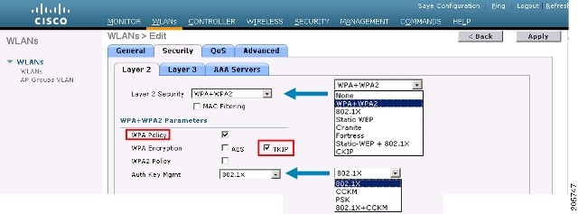
Figure 11. WPA-2 Security Settings for a WGB 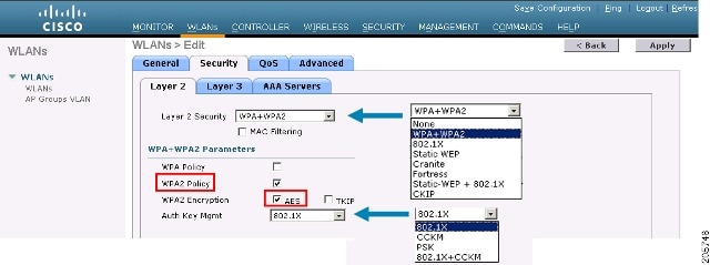
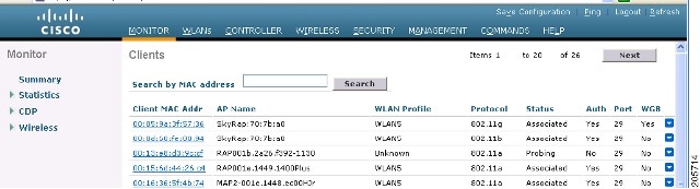
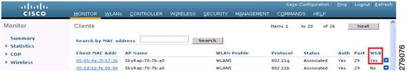
| Step 1 | Choose Monitor > Clients. |
| Step 2 | On the client summary page, click on the MAC address of the client or search for the client using its MAC address. |
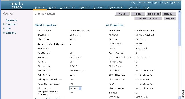
| Step 3 | In the page that appears,
note that the client type is identified as a
WGB (far right).
 |
| Step 4 | Click on the MAC address of the client to view configuration details: |
Guidelines for Configuration
Follow these guidelines when you configure:
We recommend using a 5-GHz radio for the uplink to Mesh AP infrastructure so you can take advantage of a strong client access on two 5-GHz radios available on mesh access points. A 5-GHz band allows more Effective Isotropic Radiated Power (EIRP) and is less polluted. In a two-radio WGB, configure 5-GHz radio (radio 1) mode as WGB. This radio will be used to access the mesh infrastructure. Configure the second radio 2.4-GHz (radio 0) mode as Root for client access.
On the Autonomous access points, only one SSID can be assigned to the native VLAN. You cannot have multiple VLANs in one SSID on the autonomous side. SSID to VLAN mapping should be unique because this is the way to segregate traffic on different VLANs. In a unified architecture, multiple VLANs can be assigned to one WLAN (SSID).
Only one WLAN (SSID) for wireless association of the WGB to the access point infrastructure is supported. This SSID should be configured as an infrastructure SSID and should be mapped to the native VLAN.
A dynamic interface should be created in the controller for each VLAN configured in the WGB.
A second radio (2.4-GHz) on the access point should be configured for client access. You have to use the same SSID on both radios and map to the native VLAN. If you create a separate SSID, then it is not possible to map it to a native VLAN, due to the unique VLAN/SSID mapping requirements. If you try to map the SSID to another VLAN, then you do not have multiple VLAN support for wireless clients.
All Layer 2 security types are supported for the WLANs (SSIDs) for wireless client association in WGB.
This feature does not depend on the AP platform. On the controller side, both mesh and nonmesh APs are supported.
There is a limitation of 20 clients in the WGB. The 20-client limitation includes both wired and wireless clients. If the WGB is talking to autonomous access points, then the client limit is very high.
The controller treats the wireless and wired clients behind a WGB in the same manner. Features such as MAC filtering and link test are not supported for wireless WGB clients from the controller.
If required, you can run link tests for a WGB wireless client from an autonomous AP.
Multiple VLANs for wireless clients associated to a WGB are not supported.
Up to 16 multiple VLANs are supported for wired clients behind a WGB from the 7.0 release and later releases.
Roaming is supported for wireless and wired clients behind a WGB. The wireless clients on the other radio will not be dissociated by the WGB when an uplink is lost or in a roaming scenario.
We recommend that you configure radio 0 (2.4 GHz) as a Root (one of the mode of operations for Autonomous AP) and radio 1 (5 GHz) as a WGB.
Configuration Example
When you configure from the CLI, the following are mandatory:
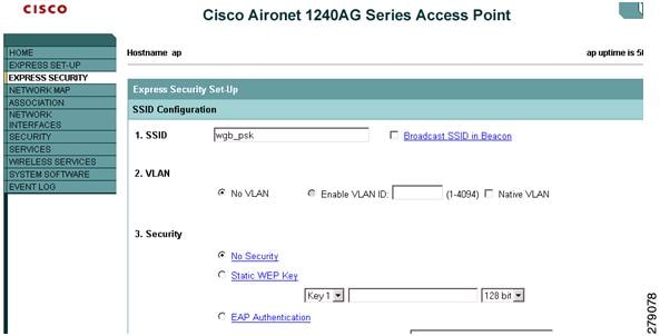
dot11 SSID (security for a WLAN can be decided based on the requirement).
Map the subinterfaces in both the radios to a single bridge group.
NoteA native VLAN is always mapped to bridge group 1 by default. For other VLANs, the bridge group number matches the VLAN number; for example, for VLAN 46, the bridge group is 46.
Map the SSID to the radio interfaces and define the role of the radio interfaces.
In the following example, one SSID (WGBTEST) is used in both radios, and the SSID is the infrastructure SSID mapped to NATIVE VLAN 51. All radio interfaces are mapped to bridge group -1.
WGB1#config t
WGB1(config)#interface Dot11Radio1.51
WGB1(config-subif)#encapsulation dot1q 51 native
WGB1(config-subif)#bridge-group 1
WGB1(config-subif)#exit
WGB1(config)#interface Dot11Radio0.51
WGB1(config-subif)#encapsulation dot1q 51 native
WGB1(config-subif)#bridge-group 1
WGB1(config-subif)#exit
WGB1(config)#dot11 ssid WGBTEST
WGB1(config-ssid)#VLAN 51
WGB1(config-ssid)#authentication open
WGB1(config-ssid)#infrastructiure-ssid
WGB1(config-ssid)#exit
WGB1(config)#interface Dot11Radio1
WGB1(config-if)#ssid WGBTEST
WGB1(config-if)#station-role workgroup-bridge
WGB1(config-if)#exit
WGB1(config)#interface Dot11Radio0
WGB1(config-if)#ssid WGBTEST
WGB1(config-if)#station-role root
WGB1(config-if)#exit
You can also use the GUI of an autonomous AP for configuration. From the GUI, subinterfaces are automatically created after the VLAN is defined.
WGB Association Check
Both the WGB association to the controller and the wireless client association to WGB can be verified by entering the show dot11 associations client command in autonomous AP.
WGB#show dot11 associations client

802.11 Client Stations on Dot11Radio1:

SSID [WGBTEST] :
MAC Address |
IP Address |
Device |
Name |
Parent |
State |
0024.130f.920e |
209.165.200.225 |
LWAPP-Parent |
RAPSB |
- |
Assoc |
From the controller, choose Monitor > Clients. The WGB and the wireless/wired client behind the WGB are updated and the wireless/wired client are shown as the WGB client.


Link Test Result
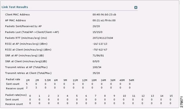
A link test can also be run from the controller CLI using the following command:
(Cisco Controller) > linktest client mac-address
Link tests from the controller are only limited to the WGB, and they cannot be run beyond the WGB from the controller to a wired or wireless client connected to the WGB. You can run link tests for the wireless client connected to the WGB from the WGB itself using the following command:
ap#dot11 dot11Radio 0 linktest target client-mac-address
Start linktest to 0040.96b8.d462, 100 512 byte packets
ap#
POOR (4% lost) |
Time (msec) |
Strength (dBm) |
SNR Quality |
Retries |
|||
In |
Out |
In |
Out |
In |
Out |
||
Sent: 100 |
Avg. 22 |
-37 |
-83 |
48 |
3 |
Tot. 34 |
35 |
Lost to Tgt: 4 |
Max. 112 |
-34 |
-78 |
61 |
10 |
Max. 10 |
5 |
Lost to Src: 4 |
Min. 0 |
-40 |
-87 |
15 |
3 |
||
Rates (Src/Tgt)     24Mb 0/5  36Mb 25/0  48Mb 73/0  54Mb 2/91
Linktest Done in 24.464 msec
WGB Wired/Wireless Client
You can also use the following commands to know the summary of WGBs and clients associated with a Cisco lightweight access point:
(Cisco Controller) > show wgb summary
Number of WGBs................................... 2
MAC Address |
IP Address |
AP Name |
Status |
WLAN |
Auth |
Protocol |
Clients |
00:1d:70:97:bd:e8 |
209.165.200.225 |
c1240 |
Assoc |
2 |
Yes |
802.11a |
2 |
00:1e:be:27:5f:e2 |
209.165.200.226 |
c1240 |
Assoc |
2 |
Yes |
802.11a |
5 |
(Cisco Controller) > show client summary

Number of Clients................................ 7
MAC Address |
AP Name |
Status |
WLAN/Guest-Lan |
Auth |
Protocol |
Port |
Wired |
00:00:24:ca:a9:b4 |
R14 |
Associated |
1 |
Yes |
N/A |
29 |
No |
00:24:c4:a0:61:3a |
R14 |
Associated |
1 |
Yes |
802.11a |
29 |
No |
00:24:c4:a0:61:f4 |
R14 |
Associated |
1 |
Yes |
802.11a |
29 |
No |
00:24:c4:a0:61:f8 |
R14 |
Associated |
1 |
Yes |
802.11a |
29 |
No |
00:24:c4:a0:62:0a |
R14 |
Associated |
1 |
Yes |
802.11a |
29 |
No |
00:24:c4:a0:62:42 |
R14 |
Associated |
1 |
Yes |
802.11a |
29 |
No |
00:24:c4:a0:71:d2 |
R14 |
Associated |
1 |
Yes |
802.11a |
29 |
No |
(Cisco Controller) > show wgb detail 00:1e:be:27:5f:e2

Number of wired client(s): 5
MAC Address |
IP Address |
AP Name |
Mobility |
WLAN |
Auth |
00:16:c7:5d:b4:8f |
Unknown |
c1240 |
Local |
2 |
No |
00:21:91:f8:e9:ae |
209.165.200.232 |
c1240 |
Local |
2 |
Yes |
00:21:55:04:07:b5 |
209.165.200.234 |
c1240 |
Local |
2 |
Yes |
00:1e:58:31:c7:4a |
209.165.200.236 |
c1240 |
Local |
2 |
Yes |
00:23:04:9a:0b:12 |
Unknown |
c1240 |
Local |
2 |
No |
Client Roaming
High-speed roaming of Cisco Compatible Extension (CX), version 4 (v4) clients is supported at speeds up to 70 miles per hour in outdoor mesh deployments. An example application might be maintaining communication with a terminal in an emergency vehicle as it moves within a mesh public network.
Three Cisco CX v4 Layer 2 client roaming enhancements are supported:
-
Access point assisted roaming—Helps clients save scanning time. When a Cisco CX v4 client associates to an access point, it sends an information packet to the new access point listing the characteristics of its previous access point. Roaming time decreases when the client recognizes and uses an access point list built by compiling all previous access points to which each client was associated and sent (unicast) to the client immediately after association. The access point list contains the channels, BSSIDs of neighbor access points that support the client’s current SSID(s), and time elapsed since disassociation.
-
Enhanced neighbor list—Focuses on improving a Cisco CX v4 client’s roam experience and network edge performance, especially when servicing voice applications. The access point provides its associated client information about its neighbors using a neighbor-list update unicast message.
-
Roam reason report—Enables Cisco CX v4 clients to report the reason why they roamed to a new access point. It also allows network administrators to build and monitor a roam history.
Note
Client roaming is enabled by default. For more information, see the Enterprise Mobility Design Guide at http://www.cisco.com/en/US/docs/solutions/Enterprise/Mobility/emob41dg/eMob4.1.pdf
WGB Roaming Guidelines
Follow these guidelines for WGB roaming:
Configuring a WGB for roaming—If a WGB is mobile, you can configure it to scan for a better radio connection to a parent access point or bridge. Use the ap(config-if)#mobile station period 3 threshold 50 command to configure the workgroup bridge as a mobile station.
When you enable this setting, the WGB scans for a new parent association when it encounters a poor Received Signal Strength Indicator (RSSI), excessive radio interference, or a high frame-loss percentage. Using these criteria, a WGB configured as a mobile station searches for a new parent association and roams to a new parent before it loses its current association. When the mobile station setting is disabled (the default setting), a WGB does not search for a new association until it loses its current association.
Configuring a WGB for Limited Channel Scanning—In mobile environments such as railroads, a WGB instead of scanning all the channels is restricted to scan only a set of limited channels to reduce the hand-off delay when the WGB roams from one access point to another. By limiting the number of channels, the WGB scans only those required channels; the mobile WGB achieves and maintains a continuous wireless LAN connection with fast and smooth roaming. This limited channel set is configured using the ap(config-if)#mobile station scan set of channels.
This command invokes scanning to all or specified channels. There is no limitation on the maximum number of channels that can be configured. The maximum number of channels that can be configured is restricted only by the number of channels that a radio can support. When executed, the WGB scans only this limited channel set. This limited channel feature also affects the known channel list that the WGB receives from the access point to which it is currently associated. Channels are added to the known channel list only if they are also part of the limited channel set.
Configuration Example
When you configure from the CLI, the following are mandatory:
-
dot11 SSID (security for a WLAN can be decided based on the requirement).
-
Map the subinterfaces in both the radios to a single bridge group.
Note
A native VLAN is always mapped to bridge group 1 by default. For other VLANs, the bridge group number matches the VLAN number; for example, for VLAN 46, the bridge group is 46.
-
Map the SSID to the radio interfaces and define the role of the radio interfaces.
In the following example, one SSID (WGBTEST) is used in both radios, and the SSID is the infrastructure SSID mapped to NATIVE VLAN 51. All radio interfaces are mapped to bridge group -1.
WGB1#config t
WGB1(config)#interface Dot11Radio1.51
WGB1(config-subif)#encapsulation dot1q 51 native
WGB1(config-subif)#bridge-group 1
WGB1(config-subif)#exit
WGB1(config)#interface Dot11Radio0.51
WGB1(config-subif)#encapsulation dot1q 51 native
WGB1(config-subif)#bridge-group 1
WGB1(config-subif)#exit
WGB1(config)#dot11 ssid WGBTEST
WGB1(config-ssid)#VLAN 51
WGB1(config-ssid)#authentication open
WGB1(config-ssid)#infrastructiure-ssid
WGB1(config-ssid)#exit
WGB1(config)#interface Dot11Radio1
WGB1(config-if)#ssid WGBTEST
WGB1(config-if)#station-role workgroup-bridge
WGB1(config-if)#exit
WGB1(config)#interface Dot11Radio0
WGB1(config-if)#ssid WGBTEST
WGB1(config-if)#station-role root
WGB1(config-if)#exit
You can also use the GUI of an autonomous AP for configuration. From the GUI, subinterfaces are automatically created after the VLAN is defined.
Troubleshooting Tips
If a wireless client is not associated with a WGB, use the following steps to troubleshoot the problem:
Verify the client configuration and ensure that the client configuration is correct.
Check the show bridge command output in autonomous AP, and confirm that the AP is reading the client MAC address from the right interface.
Confirm that the subinterfaces corresponding to specific VLANs in different interfaces are mapped to the same bridge group.
If required, clear the bridge entry using the clear bridge command (remember that this command will remove all wired and wireless clients associated in a WGB and make them associate again).
Check the show dot11 association command output and confirm that the WGB is associated with the controller.
Ensure that the WGB has not exceeded its 20-client limitation.
In a normal scenario, if the show bridge and show dot11 association command outputs are as expected, wireless client association should be successful.
Configuring Voice Parameters in Indoor Mesh Networks
You can configure call admission control (CAC) and QoS on the controller to manage voice and video quality on the mesh network.
The indoor mesh access points are 802.11e capable, and QoS is supported on the local 2.4 and 5-Ghz access radio and the 2.4 and 5 Ghz access radio and the 2.4 and 5 Ghz backhaul radio. CAC is supported on the backhaul and the CCXv4 clients (which provides CAC between the mesh access point and the client)
Note | Voice is supported only on indoor mesh networks. Voice is supported on a best-effort basis in the outdoors in a mesh network. |
- Call Admission Control
- Quality of Service and Differentiated Services Code Point Marking
- Guidelines For Using Voice on the Mesh Network
Call Admission Control
Call Admission Control (CAC) enables a mesh access point to maintain controlled quality of service (QoS) when the wireless LAN is experiencing congestion. The Wi-Fi Multimedia (WMM) protocol deployed in CCXv3 ensures sufficient QoS as long as the wireless LAN is not congested. However, to maintain QoS under differing network loads, CAC in CCXv4 or later is required.
Note | CAC is supported in Cisco Compatible Extensions (CCX) v4 or later. See Chapter 6 of the Cisco Wireless LAN Controller Configuration Guide at http://www.cisco.com/en/US/docs/wireless/controller/7.0/configuration/guide/c70sol.html |
Two types of CAC are available for access points: bandwidth-based CAC and load-based CAC. All calls on a mesh network are bandwidth-based, so mesh access points use only bandwidth-based CAC.
Bandwidth-based, or static CAC enables the client to specify how much bandwidth or shared medium time is required to accept a new call. Each access point determines whether it is capable of accommodating a particular call by looking at the bandwidth available and compares it against the bandwidth required for the call. If there is not enough bandwidth available to maintain the maximum allowed number of calls with acceptable quality, the mesh access point rejects the call.
Quality of Service and Differentiated Services Code Point Marking
Cisco supports 802.11e on the local access and on the backhaul. Mesh access points prioritize user traffic based on classification, and therefore all user traffic is treated on a best-effort basis.
Resources available to users of the mesh vary, according to the location within the mesh, and a configuration that provides a bandwidth limitation in one point of the network can result in an oversubscription in other parts of the network.
Similarly, limiting clients on their percentage of RF is not suitable for mesh clients. The limiting resource is not the client WLAN, but the resources available on the mesh backhaul.
Similar to wired Ethernet networks, 802.11 WLANs employ Carrier Sense Multiple Access (CSMA), but instead of using collision detection (CD), WLANs use collision avoidance (CA), which means that instead of each station trying to transmit as soon as the medium is free, WLAN devices will use a collision avoidance mechanism to prevent multiple stations from transmitting at the same time.
The collision avoidance mechanism uses two values called CWmin and CWmax. CW stands for contention window. The CW determines what additional amount of time an endpoint should wait, after the interframe space (IFS), to attend to transmit a packet. Enhanced distributed coordination function (EDCF) is a model that allows end devices that have delay-sensitive multimedia traffic to modify their CWmin and CWmax values to allow for statically greater (and more frequent) access to the medium.
Cisco access points support EDCF-like QoS. This provides up to eight queues for QoS.
These queues can be allocated in several different ways, as follows:
AP1500s, with Cisco controllers, provide a minimal integrated services capability at the controller, in which client streams have maximum bandwidth limits, and a more robust differentiated services (diffServ) capability based on the IP DSCP values and QoS WLAN overrides.
When the queue capacity has been reached, additional frames are dropped (tail drop).
Encapsulations
Several encapsulations are used by the mesh system. These encapsulations include CAPWAP control and data between the controller and RAP, over the mesh backhaul, and between the mesh access point and its client(s). The encapsulation of bridging traffic (noncontroller traffic from a LAN) over the backhaul is the same as the encapsulation of CAPWAP data.
There are two encapsulations between the controller and the RAP. The first is for CAPWAP control, and the second is for CAPWAP data. In the control instance, CAPWAP is used as a container for control information and directives. In the instance of CAPWAP data, the entire packet, including the Ethernet and IP headers, is sent in the CAPWAP container.
For the backhaul, there is only one type of encapsulation, encapsulating mesh traffic. However, two types of traffic are encapsulated: bridging traffic and CAPWAP control and data traffic. Both types of traffic are encapsulated in a proprietary mesh header.
In the case of bridging traffic, the entire packet Ethernet frame is encapsulated in the mesh header.
All backhaul frames are treated identically, regardless of whether they are MAP to MAP, RAP to MAP, or MAP to RAP.

Note | Mesh Data DTLS encryption is only supported on the wave 2 Mesh AP such as 1540 and 1560 models only. |
Queuing on the Mesh Access Point
The mesh access point uses a high speed CPU to process ingress frames, Ethernet, and wireless on a first-come, first-serve basis. These frames are queued for transmission to the appropriate output device, either Ethernet or wireless. Egress frames can be destined for either the 802.11 client network, the 802.11 backhaul network, or Ethernet.
AP1500s support four FIFOs for wireless client transmissions. These FIFOs correspond to the 802.11e platinum, gold, silver, and bronze queues, and obey the 802.11e transmission rules for those queues. The FIFOs have a user configurable queue depth.
The backhaul (frames destined for another outdoor mesh access point) uses four FIFOs, although user traffic is limited to gold, silver, and bronze. The platinum queue is used exclusively for CAPWAP control traffic and voice, and has been reworked from the standard 802.11e parameters for CWmin, CWmax, and so on, to provide more robust transmission but higher latencies.
The 802.11e parameters for CWmin, CWmax, and so on, for the gold queue have been reworked to provide lower latency at the expense of slightly higher error rate and aggressiveness. The purpose of these changes is to provide a channel that is more conducive to video applications.
Frames that are destined for Ethernet are queued as FIFO, up to the maximum available transmit buffer pool (256 frames). There is support for a Layer 3 IP Differentiated Services Code Point (DSCP), so marking of the packets is there as well.
In the controller to RAP path for the data traffic, the outer DSCP value is set to the DSCP value of the incoming IP frame. If the interface is in tagged mode, the controller sets the 802.1Q VLAN ID and derives the 802.1p UP (outer) from 802.1p UP incoming and the WLAN default priority ceiling. Frames with VLAN ID 0 are not tagged.
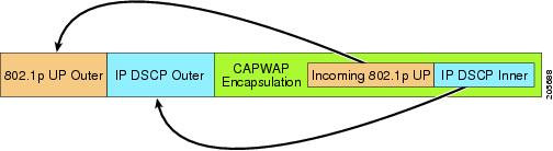
For CAPWAP control traffic the IP DSCP value is set to 46, and the 802.1p user priority is set to 7. Prior to transmission of a wireless frame over the backhaul, regardless of node pairing (RAP/MAP) or direction, the DSCP value in the outer header is used to determine a backhaul priority. The following sections describe the mapping between the four backhaul queues the mesh access point uses and the DSCP values shown in Backhaul Path QoS.
Note | The platinum backhaul queue is reserved for CAPWAP control traffic, IP control traffic, and voice packets. DHCP, DNS, and ARP requests are also transmitted at the platinum QoS level. The mesh software inspects each frame to determine whether it is a CAPWAP control or IP control frame in order to protect the platinum queue from use by non-CAPWAP applications. |
For a MAP to the client path, there are two different procedures, depending on whether the client is a WMM client or a normal client. If the client is a WMM client, the DSCP value in the outer frame is examined, and the 802.11e priority queue is used.
If the client is not a WMM client, the WLAN override (as configured at the controller) determines the 802.11e queue (bronze, gold, platinum, or silver), on which the packet is transmitted.
For a client of a mesh access point, there are modifications made to incoming client frames in preparation for transmission on the mesh backhaul or Ethernet. For WMM clients, a MAP illustrates the way in which the outer DSCP value is set from an incoming WMM client frame.
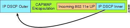
The minimum value of the incoming 802.11e user priority and the WLAN override priority is translated using the information listed in Table 3 to determine the DSCP value of the IP frame. For example, if the incoming frame has as its value a priority indicating the gold priority, but the WLAN is configured for the silver priority, the minimum priority of silver is used to determine the DSCP value.
If there is no incoming WMM priority, the default WLAN priority is used to generate the DSCP value in the outer header. If the frame is an originated CAPWAP control frame, the DSCP value of 46 is placed in the outer header.
With the 5.2 code enhancements, DSCP information is preserved in an AWPP header.
All wired client traffic is restricted to a maximum 802.1p UP value of 5, except DHCP/DNS and ARP packets, which go through the platinum queue.
The non-WMM wireless client traffic gets the default QoS priority of its WLAN. The WMM wireless client traffic may have a maximum 802.11e value of 6, but it must be below the QoS profile configured for its WLAN. If admission control is configured, WMM clients must use TSPEC signaling and get admitted by CAC.
The CAPWAPP data traffic carries wireless client traffic and has the same priority and treatment as wireless client traffic.
Now that the DSCP value is determined, the rules described earlier for the backhaul path from the RAP to the MAP are used to further determine the backhaul queue on which the frame is transmitted. Frames transmitted from the RAP to the controller are not tagged. The outer DSCP values are left intact, as they were first constructed.
Bridging Backhaul Packets
Bridging services are treated a little differently from regular controller-based services. There is no outer DSCP value in bridging packets because they are not CAPWAP encapsulated. Therefore, the DSCP value in the IP header as it was received by the mesh access point is used to index into the table as described in the path from the mesh access point to the mesh access point (backhaul).
Bridging Packets from and to a LAN
Packets received from a station on a LAN are not modified in any way. There is no override value for the LAN priority. Therefore, the LAN must be properly secured in bridging mode. The only protection offered to the mesh backhaul is that non-CAPWAP control frames that map to the platinum queue are demoted to the gold queue.
Packets are transmitted to the LAN precisely as they are received on the Ethernet ingress at entry to the mesh.
The only way to integrate QoS between Ethernet ports on AP1500 and 802.11a is by tagging Ethernet packets with DSCP. AP1500s take the Ethernet packet with DSCP and places it in the appropriate 802.11e queue.
AP1500s do not tag DSCP itself:
-
On the ingress port, the AP1500 sees a DSCP tag, encapsulates the Ethernet frame, and applies the corresponding 802.11e priority.
-
On the egress port, the AP1500 decapsulates the Ethernet frame, and places it on the wire with an untouched DSCP field.
Ethernet devices, such as video cameras, should have the capability to mark the bits with DSCP value to take advantage of QoS.
Note | QoS only is relevant when there is congestion on the network. |
Guidelines For Using Voice on the Mesh Network
Follow these guidelines when you use voice on the mesh network:
-
Voice is supported only on indoor mesh networks. For outdoors, voice is supported on a best-effort basis on a mesh infrastructure.
-
When voice is operating on a mesh network, calls must not traverse more than two hops. Each sector must be configured to require no more than two hops for voice.
-
RF considerations for voice networks are as follows:
-
Voice needs RSSI and SNR values that are at least 15 dB higher than data requirements
-
RSSI of -67 dBm for all data rates should be the goal for 11b/g/n and 11a/n
-
SNR should be 25 dB for the data rate used by client to connect to the AP
-
Packet error rate (PER) should be configured for a value of one percent or less
-
On the 802.11a/n/ac or 802.11b/g/n > Global parameters page, do the following:
-
On the 802.11a/n/ac or 802.11b/g/n > Voice parameters page, do the following:
-
On the 802.11a/n/ac or 802.11b/g/n > EDCA parameters page, you should do the following:
-
On the WLANs > Edit > QoS page, you should do the following:
-
On the WLANs > Edit > QoS page, you should do the following:
Enabling Mesh Multicast Containment for Video
You can use the controller CLI to configure three mesh multicast modes to manage video camera broadcasts on all mesh access points. When enabled, these modes reduce unnecessary multicast transmissions within the mesh network and conserve backhaul bandwidth.
Mesh multicast modes determine how bridging-enabled access points MAP and RAP send multicasts among Ethernet LANs within a mesh network. Mesh multicast modes manage non-CAPWAP multicast traffic only. CAPWAP multicast traffic is governed by a different mechanism.
The three mesh multicast modes are as follows:
Regular mode—Data is multicast across the entire mesh network and all its segments by bridging-enabled RAP and MAP.
In-only mode—Multicast packets received from the Ethernet by a MAP are forwarded to the RAP’s Ethernet network. No additional forwarding occurs, which ensures that non-CAPWAP multicasts received by the RAP are not sent back to the MAP Ethernet networks within the mesh network (their point of origin), and MAP to MAP multicasts do not occur because they are filtered out.
NoteWhen an HSRP configuration is in operation on a mesh network, we recommend the In-Out multicast mode be configured.
In-out mode—The RAP and MAP both multicast but in a different manner:
If multicast packets are received at a MAP over Ethernet, they are sent to the RAP; however, they are not sent to other MAP over Ethernet, and the MAP to MAP packets are filtered out of the multicast.
If multicast packets are received at a RAP over Ethernet, they are sent to all the MAPs and their respective Ethernet networks. When the in-out mode is in operation, it is important to properly partition your network to ensure that a multicast sent by one RAP is not received by another RAP on the same Ethernet segment and then sent back into the network.
NoteIf 802.11b clients need to receive CAPWAP multicasts, then multicast must be enabled globally on the controller as well as on the mesh network (using the config network multicast global enable CLI command). If multicast does not need to extend to 802.11b clients beyond the mesh network, the global multicast parameter should be disabled (using the config network multicast global disable CLI command).
Viewing the Voice Details for Mesh Networks (CLI)

To view the total number of voice calls and the bandwidth used for voice calls on each RAP, enter this command:
Information similar to the following appears:
AP Name          Slot#   Radio  BW Used/Max  Calls
------------    -------  -----  -----------  -----
SB_RAP1              0   11b/g     0/23437    0
                     1   11a       0/23437    2
SB_MAP1              0   11b/g     0/23437    0
                     1   11a       0/23437    0
SB_MAP2              0   11b/g     0/23437    0
                     1   11a       0/23437    0
SB_MAP3              0   11b/g     0/23437    0
                     1   11a      0/23437    0?
To view the mesh tree topology for the network and the bandwidth utilization (used/maximum available) of voice calls and video links for each mesh access point and radio, enter this command:
show mesh cac bwused {voice | video} AP_name
Information similar to the following appears:
AP Name       Slot#    Radio      BW Used/Max
------------- -------  -----      -----------
SB_RAP1         0      11b/g       1016/23437
                1      11a         3048/23437
|SB_MAP1        0      11b/g       0/23437
                1      11a         3048/23437
||  SB_MAP2     0      11b/g       2032/23437
                1      11a         3048/23437
||| SB_MAP3     0      11b/g       0/23437
                1      11a         0/23437
NoteThe bars (|) to the left of the AP Name field indicate the number of hops that the MAP is from its RAP.
NoteWhen the radio type is the same, the backhaul bandwidth utilization (bw used/max) at each hop is identical. For example, mesh access points map1, map2, map3, and rap1 are all on the same radio backhaul (802.11a) and are using the same bandwidth (3048). All of the calls are in the same interference domain. A call placed anywhere in that domain affects the others.
To view the mesh tree topology for the network and display the number of voice calls that are in progress by mesh access point radio, enter this command:
Information similar to the following appears:

AP Name             Slot#   Radio     Calls
-------------      -------  -----    -----
SB_RAP1              0      11b/g      0
                     1      11a        0
|   SB_MAP1          0      11b/g      0
                     1      11a        0
||  SB_MAP2          0      11b/g      1
                     1      11a        0
||| SB_MAP3          0      11b/g      0
                     1      11a        0
NoteEach call received by a mesh access point radio causes the appropriate calls summary column to increment by one. For example, if a call is received on the 802.11b/g radio on map2, then a value of one is added to the existing value in that radio’s calls column. In this case, the new call is the only active call on the 802.11b/g radio of map2. If one call is active when a new call is received, the resulting value is two.
To view the mesh tree topology for the network and display the voice calls that are in progress, enter this command:
show mesh cac callpath AP_name
Information similar to the following appears:

AP Name             Slot#   Radio     Calls
-------------      -------  -----    -----
SB_RAP1              0      11b/g      0
                     1      11a        1
|   SB_MAP1          0      11b/g      0
                     1      11a        1
||  SB_MAP2          0      11b/g      1
                     1      11a        1
||| SB_MAP3          0      11b/g      0
                     1      11a        0
NoteThe calls column for each mesh access point radio in a call path increments by one. For example, for a call that initiates at map2 (show mesh cac call path SB_MAP2) and terminates at rap1 by way of map1, one call is added to the map2 802.11b/g and 802.11a radio calls column, one call to the map1 802.11a backhaul radio calls column, and one call to the rap1 802.11a backhaul radio calls column.
To view the mesh tree topology of the network, the voice calls that are rejected at the mesh access point radio due to insufficient bandwidth, and the corresponding mesh access point radio where the rejection occurred, enter this command:
show mesh cac rejected AP_name
Information similar to the following appears:
AP Name             Slot#   Radio     Calls
-------------      -------  -----    -----
SB_RAP1              0      11b/g      0
                     1      11a        0
|   SB_MAP1          0      11b/g      0
                     1      11a        0
||  SB_MAP2          0      11b/g      1
                     1      11a        0
||| SB_MAP3          0      11b/g      0
                     1      11a        0
NoteIf a call is rejected at the map2 802.11b/g radio, its calls column increments by one.
To view the number of bronze, silver, gold, platinum, and management queues active on the specified access point, enter this command. The peak and average length of each queue are shown as well as the overflow count.
Information similar to the following appears:
Queue Type  Overflows  Peak length  Average length
 ----------  ---------  -----------  --------------
 Silver      0          1            0.000
 Gold        0          4            0.004
 Platinum    0          4            0.001
 Bronze      0          0            0.000
 Management  0          0            0.000
Overflows—The total number of packets dropped due to queue overflow.
Peak Length—The peak number of packets waiting in the queue during the defined statistics time interval.
Average Length—The average number of packets waiting in the queue during the defined statistics time interval.
Enabling Multicast on the Mesh Network (CLI)
To enable multicast mode on the mesh network to receive multicasts from beyond the mesh networks, enter these commands:
config network multicast global enable
config mesh multicast {regular | in | in-out}
To enable multicast mode only the mesh network (multicasts do not need to extend to 802.11b clients beyond the mesh network), enter these commands:
config network multicast global disable
config mesh multicast {regular | in | in-out}
Note | Multicast for mesh networks cannot be enabled using the controller GUI. |
IGMP Snooping
IGMP snooping delivers improved RF usage through selective multicast forwarding and optimizes packet forwarding in voice and video applications.
A mesh access point transmits multicast packets only if a client is associated with the mesh access point that is subscribed to the multicast group. So, when IGMP snooping is enabled, only that multicast traffic relevant to given hosts is forwarded.
To enable IGMP snooping on the controller, enter the following command:
configure network multicast igmp snooping enable
A client sends an IGMP join that travels through the mesh access point to the controller. The controller intercepts the join and creates a table entry for the client in the multicast group. The controller then proxies the IGMP join through the upstream switch or router.
You can query the status of the IGMP groups on a router by entering the following command:
router# show ip gmp groups
IGMP Connected Group Membership

Group Address    Interface   Uptime  Expires    Last Reporter
233.0.0.1        Vlan119     3w1d    00:01:52   10.1.1.130
For Layer 3 roaming, an IGMP query is sent to the client’s WLAN. The controller modifies the client’s response before forwarding and changes the source IP address to the controller’s dynamic interface IP address.
The network hears the controller’s request for the multicast group and forwards the multicast to the new controller.
For more information about video, see the following:
Video Surveillance over Mesh Deployment Guide: http://www.cisco.com/en/US/tech/tk722/tk809/technologies_tech_note09186a0080b02511.shtml
Cisco Unified Wireless Network Solution: VideoStream Deployment Guide: http://www.cisco.com/en/US/products/ps10315/products_tech_note09186a0080b6e11e.shtml
Locally Significant Certificates for Mesh APs
Until the 7.0 release, mesh APs supported only the Manufactured Installed Certificate (MIC) to authenticate and get authenticated by controllers to join the controller. You might have had to have your own public key infrastructure (PKI) to control CAs, to define policies, to define validity periods, to define restrictions and usages on the certificates that are generated, and get these certificates installed on the APs and controllers. After these customer-generated or locally significant certificates (LSCs) are present on the APs and controllers, the devices start using these LSCs, to join, authenticate, and derive a session key. Cisco supported normal APs from the 5.2 release and later releases and extended the support for mesh APs as well from the 7.0 release.
Graceful fallback to MIC if APs are unable to join the controller with LSC certificates—Local APs try to join a controller with an LSC for the number of times that are configured on the controller (the default value is 3). After these trials, the AP deletes the LSC and tries to join a controller with an MIC.
Mesh APs try to join a controller with an LSC until its lonely timer expires and the AP reboots. The lonely timer is set for 40 minutes. After the reboot, the AP tries to join a controller with an MIC. If the AP is again not able to join a controller with an MIC in 40 minutes, the AP reboots and then tries to join a controller with an LSC.
NoteAn LSC in mesh APs is not deleted. An LSC is deleted in mesh APs only when the LSC is disabled on the controller, which causes the APs to reboot.
- Guidelines for Configuration
- Differences Between LSCs for Mesh APs and Normal APs
- Certificate Verification Process in LSC AP
- Getting Certificates for LSC Feature
- Configuring a Locally Significant Certificate (CLI)
- LSC-Related Commands
- Controller GUI Security Settings
- Deployment Guidelines
Guidelines for Configuration
Follow these guidelines when using LSCs for mesh APs:
This feature does not remove any preexisting certificates from an AP. It is possible for an AP to have both LSC and MIC certificates.
After an AP is provisioned with an LSC, it does not read in its MIC certificate on boot-up. A change from an LSC to an MIC will require the AP to reboot. APs do it for a fallback if they cannot be joined with an LSC.
Provisioning an LSC on an AP does not require an AP to turn off its radios, which is vital for mesh APs, which may get provisioned over-the-air.
Because mesh APs need a dot1x authentication, a CA and ID certificate is required to be installed on the server in the controller.
LSC provisioning can happen over Ethernet and over-the-air in case of MAPs.You have to connect the mesh AP to the controller through Ethernet and get the LSC certificate provisioned. After the LSC becomes the default, an AP can be connected over-the-air to the controller using the LSC certificate.
Differences Between LSCs for Mesh APs and Normal APs
CAPWAP APs use LSC for DTLS setup during a JOIN irrespective of the AP mode. Mesh APs also use the certificate for mesh security, which involves a dot1x authentication with the controller through the parent AP. After the mesh APs are provisioned with an LSC, they need to use the LSC for this purpose because MIC will not be read in.
Mesh APs use a statically configured dot1x profile to authenticate.
This profile is hardcoded to use "cisco" as the certificate issuer. This profile needs to be made configurable so that vendor certificates can be used for mesh authentication (enter the config local-auth eap-profile cert-issuer vendor "prfMaP1500LlEAuth93" command).
You must enter the config mesh lsc enable/disable command to enable or disable an LSC for mesh APs. This command will cause all the mesh APs to reboot.
Note | An LSC on mesh is open for very specific Oil and Gas customers with the 7.0 release. Initially, it is a hidden feature. The config mesh lsc enable/disable is a hidden command. Also, the config local-auth eap-profile cert-issuer vendor "prfMaP1500LlEAuth93" command is a normal command, but the "prfMaP1500LlEAuth93" profile is a hidden profile, and is not stored on the controller and is lost after the controller reboot. |
Certificate Verification Process in LSC AP
LSC-provisioned APs have both LSC and MIC certificates, but the LSC certificate will be the default one. The verification process consists of the following two steps:
Getting Certificates for LSC Feature
To configure LSC, you must first gather and install the appropriate certificates on the controller. The following steps show how to accomplish this using Microsoft 2003 Server as the CA server.
| Step 1 | Go to the CA server (http://<ip address of caserver/crtsrv) and login. |
| Step 2 | Get the CA certificate as follows: |
| Step 3 | To use the certificate on the controller, convert the downloaded certificate to PEM format. You can convert this in a Linux machine using the following command: # openssl x509 -in <input.cer> -inform DER -out <output.cer> -outform PEM |
| Step 4 | Configure the CA certificate on the controller as follows: |
| Step 5 | To install the Device certificate on the WLC, login to the CA server as mentioned in Step 1 and do the following: |
| Step 6 | Convert the device certificate obtained in the Step 5. To get the certificate, go to your internet browser options and choose exporting to a file. Follow the options from your browser to do this. You need to remember the password that you set here. To convert the certificate, use the following command in a Linux machine: |
| Step 7 | On the controller GUI, choose Command > Download File. Choose Vendor Device Certificate from the File Type drop-down list. Update the rest of the fields with the information of the TFTP server where the certificate is located and the password you set in the previous step and click Download. |
| Step 8 | Reboot the controller so that the certificates can then be used. |
| Step 9 | You can check that the certificates were successfully installed on the controller using this command: |
Configuring a Locally Significant Certificate (CLI)
To configure a locally significant certificate (LSC), follow these steps:
| Step 1 | Enable LSC and provision the LSC CA certificate in the controller. |
| Step 2 | Enter the following command: config local-auth eap-profile cert-issuer vendor prfMaP1500LlEAuth93 |
| Step 3 | Turn on the feature by entering the following command: |
| Step 4 | Connect the mesh AP through Ethernet and provision for an LSC certificate. |
| Step 5 | Let the mesh AP get a certificate and join the controller using the LSC certificate. 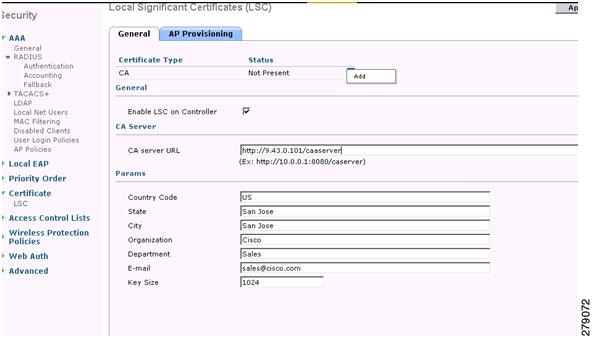 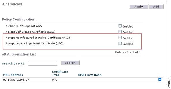 |
LSC-Related Commands
The following commands are related to LSCs:
config certificate lsc {enable | disable}
disable—To disable an LSC on the system. Use this keyword to remove the LSC device certificate and send a message to an AP, to do the same and disable an LSC, so that subsequent joins could be made using the MIC/SSC. The removal of the LSC CA cert on the WLC should be done explicitly by using the CLI to accommodate any AP that has not transitioned back to the MIC/SSC.
config certificate lsc ca-server url-path ip-address
Following is the example of the URL when using Microsoft 2003 server:
http:<ip address of CA>/sertsrv/mscep/mscep.dll
This command configures the URL to the CA server for getting the certificates. The URL contains either the domain name or the IP address, port number (typically=80), and the CGI-PATH.
Only one CA server is allowed to be configured. The CA server has to be configured to provision an LSC.
config certificate lsc ca-server delete
This command deletes the CA server configured on the controller.
config certificate lsc ca-cert {add | delete}
This command adds or deletes the LSC CA certificate into/from the controller's CA certificate database as follows:
add—Queries the configured CA server for a CA certificate using the SSCEP getca operation, and gets into the WLC and installs it permanently into the WLC database. If installed, this CA certificate is used to validate the incoming LSC device certificate from the AP.
delete—Deletes the LSC CA certificate from the WLC database.
config certificate lsc subject-params Country State City Orgn Dept Email
This command configures the parameters for the device certificate that will be created and installed on the controller and the AP.
All of these strings have 64 bytes, except for the Country that has a maximum of 3 bytes. The Common Name is automatically generated using its Ethernet MAC address. This should be given prior to the creation of the controller device certificate request.
The above parameters are sent as an LWAPP payload to the AP, so that the AP can use these parameters to generate the certReq. The CN is automatically generated on the AP using the current MIC/SSC "Cxxxx-MacAddr" format, where xxxx is the product number.
config certificate lsc ap-provision {enable | disable}
This command enables or disables the provisioning of the LSCs on the APs if the APs just joined using the SSC/MIC. If enabled, all APs that join and do not have the LSC will get provisioned.
If disabled, no more automatic provisioning will be done. This command does not affect the APs, which already have LSCs in them.
config certificate lsc ra-cert {add | delete}
We recommend this command when the CA server is a Cisco IOS CA server. The controller can use the RA to encrypt the certificate requests and make communication more secure. RA certificates are not currently supported by other external CA servers, such as MSFT.
config auth-list ap-policy lsc {enable | disable}
After getting the LSC, an AP tries to join the controller. Before the AP tries to join the controller, you must mandatorily enter this command on the controller console. By default, the config auth-list ap-policy lsc command is in the disabled state, and the APs are not allowed to join the controller using the LSC.
config auth-list ap-policy mic {enable | disable}
After getting the MIC, an AP tries to join the controller. Before the AP tries to join the controller, you must mandatorily enter this command on the controller console. By default, the config auth-list ap-policy mic command is in the enabled state. If an AP cannot join because of the enabled state, this log message on the controller side is displayed: LSC/MIC AP is not allowed to join.
show certificate lsc summary
This command displays the LSC certificates installed on the WLC. It would be the CA certificate, device certificate, and optionally, an RA certificate if the RA certificate has also been installed. It also indicates if an LSC is enabled or not.
show certificate lsc ap-provision
This command displays the status of the provisioning of the AP, whether it is enabled or disabled, and whether a provision list is present or not.
show certificate lsc ap-provision details
This command displays the list of MAC addresses present in the AP provisioning lists.
Controller GUI Security Settings
Although the settings are not directly related to the feature, it might help you in achieving the desired behavior with respect to APs provisioned with an LSC.
-
Case 1—Local MAC Authorization and Local EAP Authentication
Add the MAC address of RAP/MAP to the controller MAC filter list.
(Cisco Controller) > config macfilter mac-delimiter colon
(Cisco Controller) > config macfilter add 00:0b:85:60:92:30 0 management
-
Case 2—External MAC Authorization and Local EAP authentication
Enter the following command on the WLC:
(Cisco Controller) > config mesh security rad-mac-filter enable
Check only the external MAC filter authorization on the GUI page and follow these guidelines:
Deployment Guidelines
When using local authorization, the controller should be installed with the vendor's CA and device certificate.
When using an external AAA server, the controller should be installed with the vendor’s CA and device certificate.
Mesh security should be configured to use ‘vendor’ as the cert-issuer.
MAPs cannot move from an LSC to an MIC when they fall back to a backup controller.
The config mesh lsc {enable | disable} command is required to enable or disable an LSC for mesh APs. This command causes all the mesh APs to reboot.
 Feedback