Installation Overview

Preinstallation Checks and Installation Guidelines

Before you mount and deploy your access point, we recommend that you perform a site survey (or use the Site Planning tool) to determine the best location to install your access point.

You should have the following information about your wireless network available:

  • Access point locations

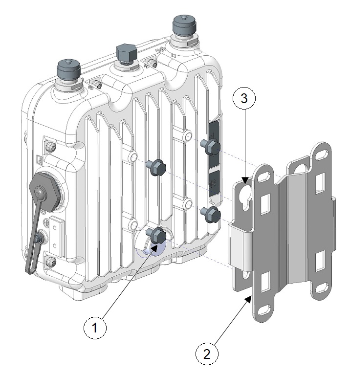
  • Access point mounting options: To a vertical or horizontal wall or a DIN rail

  • Access point power options: Use either of the following options to power the AP:

    • DC power input

    • Cisco-approved power injector

    • 802.3at (PoE+), 802.3bt, and Cisco Universal PoE (Cisco UPOE)

  • Operating temperature : -40° to +140°F (-40° to +60°C) with solar load and still air.

  • Extended operating temperature (DC powered): -58° to +167°F (-50° to +75°C) without solar loading, still air, and cold start limited to -40°C (-40°F).

  • Console access using the console port

    We recommend that you use a console cable that is one meter or less in length.


    Note


    The AP may face issues while booting if you use an unterminated console cable (not plugged into any device or terminal) or a console cable that is more than one meter in length.

We recommend that you make a site map showing access point locations so that you can record the device MAC addresses from each location and return them to the person who is planning or managing your wireless network.

Mounting the Access Point

This section provides instructions to mount the AP. Personnel mounting the AP must have knowledge of the wireless AP, bridging techniques, and grounding methods.

Installation Options

The IW9165D Access Point can be wall or pole mounted. There are two optional mounting kits: a fixed mounting kit (AIR-ACC1530-PMK1=) and a tiltable mounting kit (IW-ACC-PMK1=).


Warning


Statement 1074—Comply with Local and National Electrical Codes

To reduce risk of electric shock or fire, installation of the equipment must comply with local and national electrical codes.


Access Point Mounting Orientation

The access point can be mounted on a horizontal or vertical surface. When mounting on a vertical surface, you must ensure that the access point is oriented with the LED indicators pointing down. This positioning allows LEDs to be visible to someone on the ground below the access point.

By using the tiltable mounting bracket (Cisco PID: IW-ACC-PMK1=), IW9165D can be mounted in 45° angle other than vertical installation. There are three arrows on the front of the access point. You can choose to mount the access point with one of the these arrows pointing up by the tilt functionality of the mounting bracket.

Figure 1. Arrows on the Front of IW9165D

1

Left arrow: -45° tilt

2

Middle arrow: straight installation

3

Righ arrow: +45° tilt

You must also ensure the access point is mounted in such a way as to ensure that all antenna ports and the console port are accessible for future use.


Note


Omnidirectional antennas are vertically polarized and should be mounted vertically.


Wall Mounting the Access Point with the Fixed Mounting Kit

The optional fixed mounting kit contains a mounting bracket for wall or pole mounting. You can use the mounting bracket as a template to mark the positions of the mounting holes for your installation. You then install the mounting plate, and attach the access point when you are ready.

The following figure shows the mounting bracket dimensions.

Figure 2. Mounting Bracket Dimensions

To mount the access point on a vertical wall, follow these instructions:

Procedure


Step 1

Use the mounting bracket as a template to mark four screw hole locations on the mounting surface. See the following figure for the mounting bracket screw hole locations. Use the mounting slotted holes to attach the unit to the wall.

Figure 3. Mounting Bracket Screw Hole Locations

1

Quick Mount Keyhole Slots (for AP use)

2

Mounting Slots (used with the band clamps)

3

Bracket Mount Holes (use bolts up to 1/4" or 6 mm in diameter)

Step 2

Use four customer-supplied screws and optional screw-anchors to attach the mounting plate to the mounting surface.

Step 3

Screw an M6 x12 mm bolt into each of the four support bolt holes on the back of the access point. Do not screw the bolt all the way in; leave approximately a 0.13 inch (3.3 mm) space.

Figure 4. Attaching Mounting Bracket to the AP

1

M6 Bolts

2

Quick Mount Keyhole Slots (for AP use)

3

Mount Bracket

Step 4

Position the four bolts on the access point into the keyhole slots on the mounting bracket.

Step 5

Slide the access point down to sit securely in the quick mount notches.

Step 6

Using a 10mm wrench, secure the AP to the bracket by tightening the bolts to the bracket; torque to 30-40 in-lbs.

Figure 5. Mounting Bracket Attached to the AP

Pole Mounting the Access Point with the Tiltable Mounting Kit

The optional tiltable mounting kit can be used to install the access point on a pole. The tiltable bracket can be rotated 180° for further downward rotation. It also provides additional holes for 45° rotated installation.

To mount the access point on a pole or a wall with the tiltable mount bracket, follow these instructions:

Procedure


Step 1

Attach the mounting bracket to the access point with four M6 screws. Torque the screws to 30-40 in-lbs.

1

M6 Bolts (x4)

2

Mounting Holes

3

Mounting Bracket (for AP)

4

Pins

Step 2

Use the mounting holes (8) to attach the mounting bracket (1) to a wall, or use the radial strap slots (9) to attach the mounting bracket (1) to a pole. Slide the assembled chassis onto the bracket and rest the pins (4) on the two mounting slots (2). Use the included M8 bolts (5), split washers (6), and flat washers (7) to secure the assembled chassis to the mounting bracket (1). Ensure that the split washer (6) is between the flat washer (7) and the bolt (5), as shown in the following figure. Torque the bolts to 50-60 in-lbs to secure the chassis to the bracket.

1

Mounting Bracket (for pole or wall)

2

Mounting Slots

3

Mounting Bracket (for AP)

4

Pins

5

M8 Bolts (x4)

6

Split Washer

7

Flat Washer

8

Mounting Holes for Wall Mounting

9

Radial Strap Slots for Pole Mounting


Installing a Lightning Arrestor

Overvoltage transients can be created through lightning static discharges, switch processes, direct contact with power lines, or through earth currents. The Lightning Arrestor limits the amplitude and duration of disturbing interference voltages and improves the over voltage resistance of in-line equipment, systems, and components. A lightning arrestor installed according to these mounting instructions balances the voltage potential, thus preventing inductive interference to parallel signal lines within the protected system.

Installation Considerations

Cisco recommends that you bulkhead mount the lightning arrestor so it can be installed as a wall-feed through on the wall of the protected space.

The importance of obtaining a good ground and bonding connection cannot be overstressed. Consider these points when grounding the lightning arrestor:

  • Connect the lightning arrestor components directly to the grounding point.

  • The contact points of the ground connection must be clean and free of dust and moisture.

  • Tighten threaded contacts to the torque specified by the manufacturer.

Lightning Arrestor Installation Notes

This lightning arrestor is designed to be installed between the antenna cable that is attached to an outdoor antenna and the Cisco wireless device. You can install the lightning arrestor either indoors or outdoors. It can be connected directly to a wireless device having an external N connector. It can also be mounted inline or as a feed-through. Feed-through installations require 5/8 in. (16 mm) hole to accommodate the lightning arrestor.


Note


  • This lightning arrestor is part of a lightning arrestor kit. The kit contains a lightning arrestor and a grounding lug.

  • When you install the lightning arrestor, follow the regulations or best practices applicable to lightning protection installation in your local area.


Installing the Lightning Arrestor Outdoors

If you install the lightning arrestor outdoors, use the supplied ground lug and a heavy wire (#6 solid copper) to connect it to a good earth ground, such as a ground rod. The connection should be as short as possible.

1

Nut

4

Unprotected Side (to antenna)

2

Lockwasher

5

Protected side (to wireless device)

3

Ground lug

Cable for the Lightning Arrestor

Coaxial cable loses efficiency as the frequency increases, resulting in signal loss. The cable should be kept as short as possible because cable length also determines the amount of signal loss (the longer the run, the greater the loss).

Cisco recommends a high-quality, low-loss cable for use with the lightning arrestor.

Grounding the Access Point

In all installations, after mounting the access point, you must properly ground the unit before connecting power cables.


Warning


Statement 1024—Ground Conductor

This equipment must be grounded. To reduce the risk of electric shock, never defeat the ground conductor or operate the equipment in the absence of a suitably installed ground conductor. Contact the appropriate electrical inspection authority or an electrician if you are uncertain that suitable grounding is available.


Warning


Statement 1074—Comply with Local and National Electrical Codes

To reduce risk of electric shock or fire, installation of the equipment must comply with local and national electrical codes.


The access point is shipped with a grounding kit.

Figure 6. Access Point Grounding Kit Contents

1

Grounding lug

2

M4 screws (x2)


Note


The grounding kit also includes the oxide inhibitor, which is contained in a tube.

To ground the access point:

Procedure


Step 1

Use a crimping tool to crimp a 6-AWG ground wire (not included in the grounding kit) to the ground lug.

Step 2

Connect the supplied ground lug to the access point ground connection point using the supplied screws. Apply supplied oxide inhibitor between the ground lug and the access point ground connection.

1

AP ground connection point

2 2

Grounding lug

3

M4 screws (x2)

Step 3

Tighten the screws to 10-15 inch-lbs of torque.

Step 4

If necessary, strip the other end of the ground wire and connect it to a reliable earth ground such as a grounding rod or appropriate ground point on a grounded pole. Length of the ground cable should not exceed 1 meter, and 0.5 meter is preferred. Use supplied oxide inhibitor on the grounded interface.


Powering the Access Point

The AP supports these power sources:

  • DC power – 24–48 VDC

  • Power-over-Ethernet (PoE)

The AP can be powered via the PoE input from an inline power injector or a suitably powered switch port. Depending on the configuration and regulatory domain, the required power for full operation is 802.3at (PoE+) or 24 - 48 VDC.

For more information, see Power Sources and Power Feature Matrix.

Power Feature Matrix

The following table provides the AP power feature matrix.

Table 1. Cisco Catalyst IW9165D Heavy Duty Access Point Power Feature Matrix

Power Input

5G Radio

5G/6G Radio

GNSS

mGig Eth

RJ45 1G

24-48V

2x2

2x2

Yes

max 2.5G

Yes

802.3at

2x2

2x2

Yes

max 2.5G

Yes

802.3af

1x1

1x1

Yes

max 1G

No

Connecting a Power Injector

The AP supports the following power injector:

Table 2. Supporting Power Injectors

Power Source

Description

IW-PWRINJ-60RGDMG=

60W rated outdoor power injector, 5GE

The power injector provides DC voltage to the AP over the Ethernet cable and supports a total end-to-end Ethernet cable length of 100 m (328 ft) from the switch to the AP.

When an optional power injector powers your AP, follow these steps to complete the installation:

Procedure


Step 1

Before applying PoE to the AP, ensure that the AP is grounded (see Grounding the Access Point).

Step 2

Connect a CAT5e or better Ethernet cable from your wired LAN network to the power injector.

Note


The installer is responsible for ensuring that powering the AP from this type of power injector is allowed by local and/or national safety and telecommunications equipment standards.

Step 3

Ensure that the antennas are connected, and that ground is attached to the AP before you apply power to the AP.

Step 4

Connect a shielded outdoor-rated Ethernet (CAT5e or better) cable between the power injector and the AP's PoE-in connector.

Step 5

Connect the Ethernet cable to the AP PoE-In port.


Connecting to the DC Power Port Using Cable Gland

Follow these steps to connect to the DC power port using cable gland:

SUMMARY STEPS

  1. Disassemble PG13 cable gland and slide parts over DC cable in the order shown in the following figure:
  2. Plug 4P connector cable into the DC connector in the chassis.
  3. Thread the PG13 body (with gasket) into the chassis.
  4. Insert the grommet into the ferrule, and press it into the PG13 body.
  5. Tighten the clamp nut onto the PG13 body until the grommet compresses onto the DC cable.

DETAILED STEPS


Step 1

Disassemble PG13 cable gland and slide parts over DC cable in the order shown in the following figure:

1

DC cable

4

Grommet

2

Gasket

5

Ferrule

3

PG13 body

6

Clamp nut

Step 2

Plug 4P connector cable into the DC connector in the chassis.

Step 3

Thread the PG13 body (with gasket) into the chassis.

Step 4

Insert the grommet into the ferrule, and press it into the PG13 body.

Step 5

Tighten the clamp nut onto the PG13 body until the grommet compresses onto the DC cable.


Connecting DC Power Port Using M12 Adapter

Follow these steps to connect to the DC power port using M12 adapter:

SUMMARY STEPS

  1. Ensure the O-ring is installed on the M12 adapter before attaching the M12 adapter to the AP.
  2. Align and plug the 4-pin Micro-Fit connector into the power port of the chassis. Press M12-PWR adapter onto the chassis, and ensure that the wires are not pinched.
  3. Torque to 15-20 in-lbs to tighten the M12 adapter captive screws into the chassis.

DETAILED STEPS


Step 1

Ensure the O-ring is installed on the M12 adapter before attaching the M12 adapter to the AP.

Figure 7. Installing O-ring on the M12 Adapter

1

M12 adapter

2

O-ring

3

O-ring installed on M12 adapter

Step 2

Align and plug the 4-pin Micro-Fit connector into the power port of the chassis. Press M12-PWR adapter onto the chassis, and ensure that the wires are not pinched.

1

4-pin Micro-Fit DC connector

3

Captive screws

2

M12-PWR adapter

Step 3

Torque to 15-20 in-lbs to tighten the M12 adapter captive screws into the chassis.


Connecting an Ethernet Cable to the Access Point

Connect an Ethernet cable to the access point by using a cable gland or an M12-RJ45 adapter.

Connecting to the RJ-45 Port Using Cable Gland

Follow these steps to connect to the RJ-45 port using cable gland:

SUMMARY STEPS

  1. Disassemble PG13 cable gland and slide parts over RJ-45 cable in the order shown in the following figure:
  2. Plug the RJ-45 cable into the RJ-45 connector in the chassis.
  3. Thread the PG13 body (with gasket) into the chassis.
  4. Insert the grommet into the ferrule, and press it into the PG13 body.
  5. Tighten the clamp nut onto the PG13 body until the grommet compresses onto the RJ-45 cable.

DETAILED STEPS


Step 1

Disassemble PG13 cable gland and slide parts over RJ-45 cable in the order shown in the following figure:

1

RJ-45 cable

4

Grommet

2

Gasket

5

Ferrule

3

PG13 body

6

Clamp nut

Step 2

Plug the RJ-45 cable into the RJ-45 connector in the chassis.

Step 3

Thread the PG13 body (with gasket) into the chassis.

Step 4

Insert the grommet into the ferrule, and press it into the PG13 body.

Step 5

Tighten the clamp nut onto the PG13 body until the grommet compresses onto the RJ-45 cable.


Connecting to the RJ-45 Port Using M12 Adapter

Follow these steps to connect to the RJ-45 port using M12 adapter:

SUMMARY STEPS

  1. Ensure the O-ring is installed on the M12 adapter before attaching the M12 adapter to the AP.
  2. Align the RJ-45 tab (3) with the RJ-45 connector in the chassis, and plug the M12 adapter into the chassis. Note the orientation of RJ45 plug and connector.
  3. Torque to 15-20 in-lbs to tighten the M12 adapter captive screws into the chassis.

DETAILED STEPS


Step 1

Ensure the O-ring is installed on the M12 adapter before attaching the M12 adapter to the AP.

1

M12 adapter

2

O-ring

Step 2

Align the RJ-45 tab (3) with the RJ-45 connector in the chassis, and plug the M12 adapter into the chassis. Note the orientation of RJ45 plug and connector.

1

M12-RJ45 adapter

3

Captive screws

2

RJ-45 tab

Step 3

Torque to 15-20 in-lbs to tighten the M12 adapter captive screws into the chassis.