About Cisco Catalyst IW9165D Heavy Duty Access Point

Introduction to Cisco Catalyst IW9165D Heavy Duty Access Point

The Cisco Catalyst IW9165D Heavy Duty Access Point (hereafter referred to as IW9165D) is designed to make wireless backhaul deployment simple. It comes with a built-in directional antenna that enables long-range, high-throughput connectivity anywhere fiber is not an option, so you can create a fixed wireless infrastructure (point-to-point, point-to-multipoint, and mesh) as well as backhaul traffic from mobile devices along wayside or trackside deployments. The external antenna ports let you quickly extend your network to new places when needed and choose the right antenna based on the use cases and deployment architectures. With heavy-duty IP67 design, the IW9165D is certified to operate under wet, dusty, and extreme temperature conditions.

The IW9165D runs Cisco Ultra-Reliable Wireless Backhaul (Cisco URWB), which delivers high availability, low latency, and zero packet loss with seamless handoffs. Cisco URWB is ideal for connecting moving assets or extending your network where running fiber isn’t feasible or affordable.

A full listing of the AP's features and specifications is provided in the Cisco Catalyst IW9165 Series Data Sheet.
Cisco Catalyst IW9165D Heavy Duty Access Point Features

The Cisco Catalyst IW9165D Heavy Duty Access Point has the following features:

  • 1x 100M/1000M/2.5G Multigigabit Ethernet (RJ45)/M12 X-code autosensing PoE+ in (802.3af/at), Cisco UPOE in

  • 1x 100M/1000M/1G (RJ45)

  • Dual-radio architecture

    • 5-GHz 2x2 radio: 20, 40, and 80 MHz channels

    • 5/6-GHz 2x2 radio: 20, 40, 80, and 160 MHz channels (6 GHz availability subject to country approvals)

  • External antenna—2 x N-type

  • Integrated antenna—Built-in directional antennas

    • Peak gain 15 dBi, internal antenna, dual polarization, azimuth beamwidth 30 deg, elevation beamwidth 30 deg, frequency: 4900 to 5925 MHz

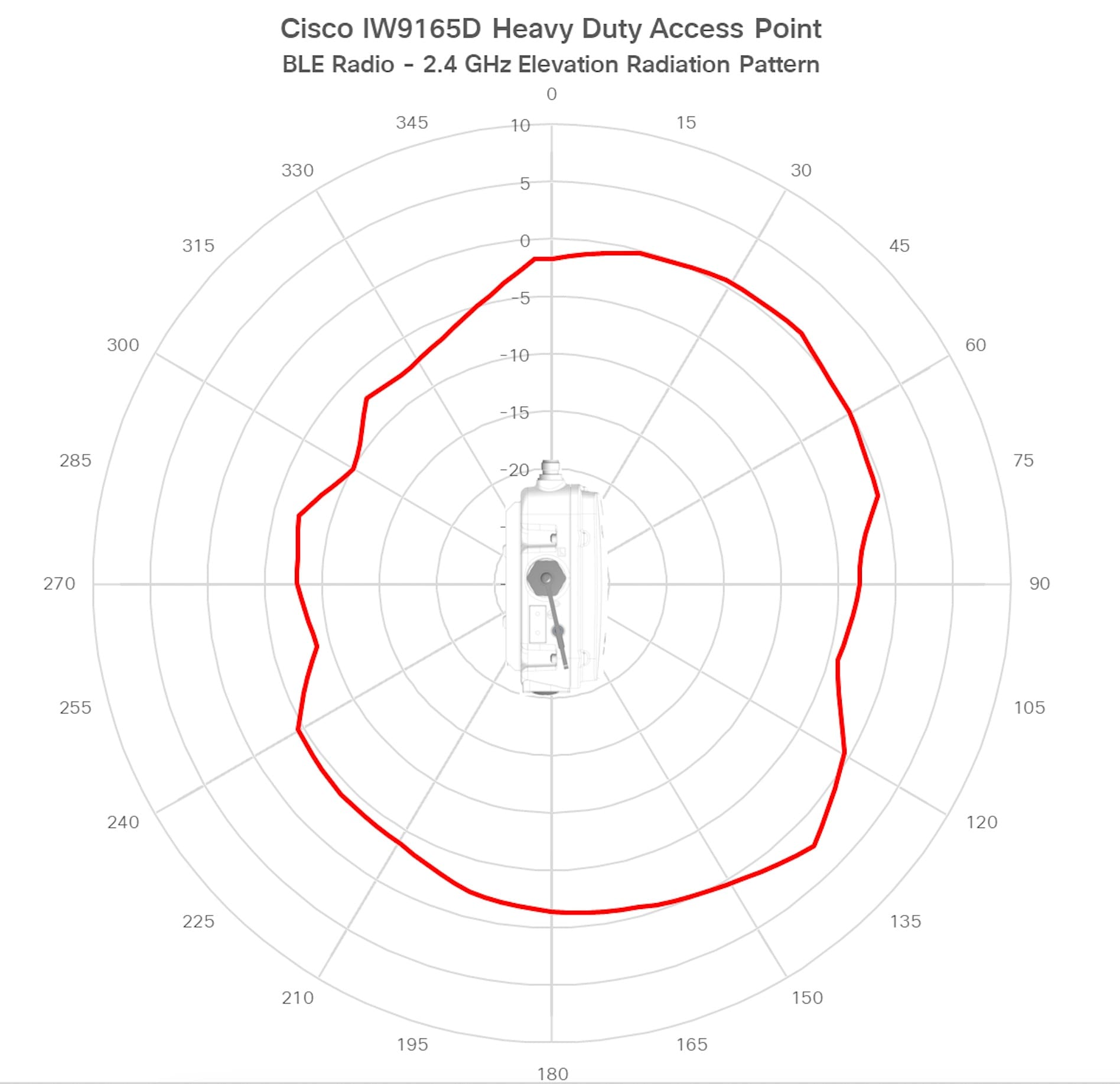
    • BLE antenna gain: 5.5 dBi max, internal antenna, linear polarization, omnidirectional

  • 1x TNC GNSS antenna port

  • Management console port (RJ45)

  • Dual power input—PoE-in 802.3af, 802.3at (PoE+), and 24-48VDC

  • Dual mounting options—Pole and wall mount

  • IP67, heavy-duty design

  • Multicolor system LED

  • Reset button

Connectors and Ports

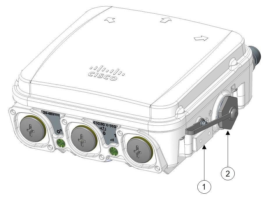
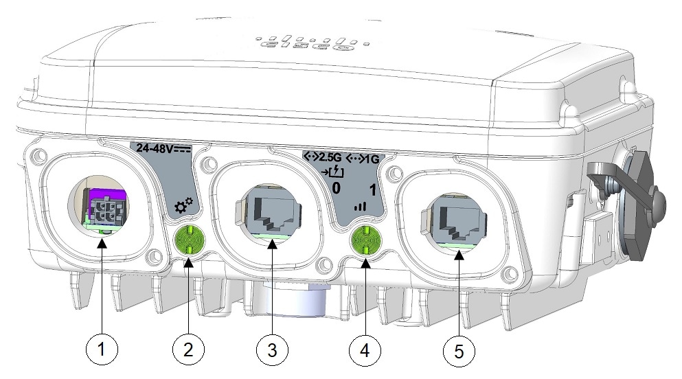
The following figures show the available ports on the AP.

Figure 1. IW9165D Right-Side Connectors and Ports

1

Ground connection point

2

Console port (RJ-45) and reset button

Figure 2. IW9165D Fron Panel Connectors and Ports

1

DC power input / M12 A-code

2

System status LED

3

100M/1000M/2.5G Multigigabit Ethernet (RJ45) / M12 X-code autosensing PoE+ in (802.3af/at), Cisco UPOE in

4

RSSI LED

5

100M/1000M/1G (RJ45) / M12 X-code

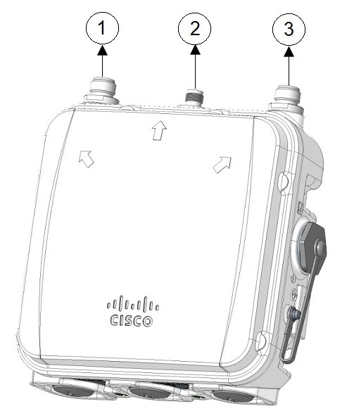
Figure 3. IW9165D Top Connectors and Ports

1

Port 1

Supports 5/6 GHz radio in 2x2 mode.

3

Port 3

Supports 5/6 GHz radio in 2x2 mode.

Supports SIA.

2

Port 2

GNSS port

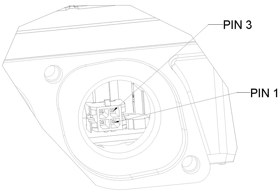
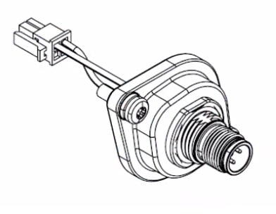
4-Pin Micro-Fit Connector for DC Power

The following figures show the 4-pin Micro-Fit connector for DC power.

Figure 4. Mating Connector: Molex Micro-Fit 43025-0400
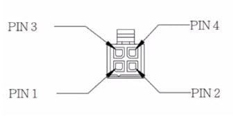
Figure 5. Mating Connector Front View

Molex Micro-Fit Pin

Assignment

Pin 1

Black ( - Negative Terminal)

Pin 2

Not assigned

Pin 3

White (+ Positive Terminal)

Pin 4

Not assigned

M12-RJ45 Adapter

M12-RJ45 adapter (Cisco PID: IW-ACC-M12ETH=) can be used to support M12 X-coded connector.


Note


M12 X-code port by using M12-RJ45 adapter can support up to 2.5G rate.


Figure 6. M12-RJ45 Adapter (Cisco PID: IW-ACC-M12ETH=)

The following table shows the M12-RJ45 adapter pinouts.

Table 1. M12-RJ45 Pinouts

RJ45

Signal

M12 X-Code

1

B1_DA+

1

2

B1_DA-

2

3

B1_DB+

3

6

B1_DB-

4

7

B1_DD+

5

8

B1_DD-

6

5

B1_DC-

7

4

B1_DC+

8

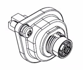
M12-PWR Adapter

M12-PWR adapter (Cisco PID: IW-ACC-M12PWR=) can be used to support M12 A-coded DC power connector.

Figure 7. M12-PWR Adapter (Cisco PID: IW-ACC-M12PWR=)

The following table shows the M12-PWR adapter pinouts.

Table 2. M12-PWR Pinouts

Micro-FIT 4P

Wire

M12 A-Code

3

RED (22 AWG)

1

2

N/C

2

1

BLACK (22 AWG)

3

4

N/C

4

Power Sources

The IW9165D is supported on these power sources:

  • DC power: 24 to 48 VDC

  • Power over Ethernet (PoE): 802.3af (PoE), 802.3at (PoE+), Cisco Universal PoE (Cisco UPOE).

Power Adapters

The IW9165D supports the following DC power adapters::

  • PID: IW-PWRADPT-MFIT4P=: Operating: -40°C to +65°C, 60W.

Power Injectors

The IW9165D supports the following power injectors:

  • IW-PWRINJ-60RGDMG=: Operating: -40°C to +70°C. Power derating of 60W at 70°C, and 65W at 65°C. Supports 100M/1G/2.5G/5G/10G rates.


Caution


When the AP is installed outdoors or in a wet or damp location, the AC branch circuit powering the AP should be provided with ground fault protection (GFCI), as required by Article 210 of the National Electrical Code (NEC).

Ethernet (PoE) Ports

The AP supports an Ethernet uplink port (also for PoE-IN). The Ethernet uplink port on the AP uses an RJ-45 connector (with weatherproofing) to link the AP to the 100BASE-T, 1000BASE-T, or 2.5G BASE-T network. The Ethernet cable is used to send and receive Ethernet data and optionally supply inline power from the power injector or a suitably powered switch port.


Tip


The AP senses the Ethernet and power signals, and automatically switch internal circuitry to match the cable connections.

The Ethernet cable must be a shielded, outdoor rated, Category 5e (CAT 5e) or better cable. The AP senses the Ethernet and power signals and automatically switches internal circuitry to match the cable connections.

Antennas and Radios

The Cisco Catalyst IW9165D Heavy Duty Access Point configuration is:

  • IW9165DH-x

The IW9165D access point has two N-type female connectors to support multiple antenna options, such as the self-identifying antennas (SIA) on designated SIA port, dual-band antennas, and single-band antennas. To see the list of supported antennas and the radio bands they operate at, see Supported External Antennas.

The IW9165D is also equiped with an internal directional antenna. For more information, see IW9165D (Internal Antenna) Radiation Patterns.

Supported External Antennas

See Connectors and Ports for the antenna ports of the IW9165D access point.

Supported Antennas

The following table shows the external antennas supported by IW9165D.

Table 3. Supported Antennas

PID

Antenna Gain (dBi)

Connector

Antenna Name

2.4 GHz

4.9 GHz

5 GHz

6 GHz

IW-ANT-PNL-59-N=

9

N female (x2)

5 GHz Dual-Port Dual-Slant +/-45 Degree Polarized Directional Panel Antenna

IW-ANT-H90-510-N=

10

N female (x2)

5 GHz Dual-Port Dual-Polarized Horn Antenna

IW-ANT-DS9-516-N=

15

15

N female (x2)

Dual-Slant Polarized Sector Antenna

IW-ANT-SS9-516-N=

15

15

N female (x2)

Dual-Linear Polarized Sector Antenna

IW-ANT-PNL-515-N=

15

15

N female (x2)

Cisco 5 GHz 15 dBi Dual-Port Polarization Diverse Directional Panel Antenna

IW-ANT-PNL5615-NS=

15

15

15

N female (x2)

5/6 GHz 15 dBi Dual-Port Polarization Diverse Directional Panel Antenna, Self-Identifying

IW-ANT-OMV-2567-N=

4

7

7

7

N male

2.4/5 GHz Tri-Band Omnidirectional Dipole Antenna, Vertically Polarized, Self-Identifying

IW-ANT-OMH-2567-N=

4

7

7

7

N male

2.4/5 GHz Tri-Band Omnidirectional Dipole Antenna, Horizontally Polarized, Self-Identifying

AIR-ANT2547V-N=

4

7

N male

Cisco Aironet Dual-Band Omnidirectional Dipole Antenna (White)

AIR-ANT2547VG-N=

4

7

N male

Cisco Aironet Dual-Band Omnidirectional Dipole Antenna (Gray)

AIR-ANT2547VG-NS=

4

7

N male

Cisco Aironet Dual-Band Omnidirectional Dipole Antenna (Gray), Self-Identifying

AIR-ANT2568VG-N=

6

8

N male

Cisco Aironet Dual-Band Omnidirectional Dipole Antenna (Gray)

AIR-ANT2568VG-NS=

6

8

N male

Cisco Aironet Dual-Band Omnidirectional Dipole Antenna (Gray), Self-Identifying

AIR-ANT5180V-N=

7

8

N male

Cisco Aironet 5 GHz 8 dBi Omnidirectional Dipole Antenna

AIR-ANT5114P2M-N=

13

N male (x2)

Cisco Aironet 5 GHz 13 dBi Dual-Port Dual-Polarized Directional Panel Antenna

Supported GNSS Antenna

The following table shows the external GNSS antennas supported by IW9165D.

Table 4. Supported GNSS Antenna

PID

Frequencies Supported

Connector

Description

ANT-GNSS-OUT-TNC=

1560 - 1608 MHz

TNC male

Outdoor Active GNSS Antenna with 15-ft. integrated cable

For installation instructions and detailed information on any of these antennas, refer to the antenna data sheet on Cisco.com, or see the antenna guides at:

Follow all safety precautions when installing the antennas. For information on safety, see Safety Precautions when Installing Antennas.

IW9165D (Internal Antenna) Radiation Patterns

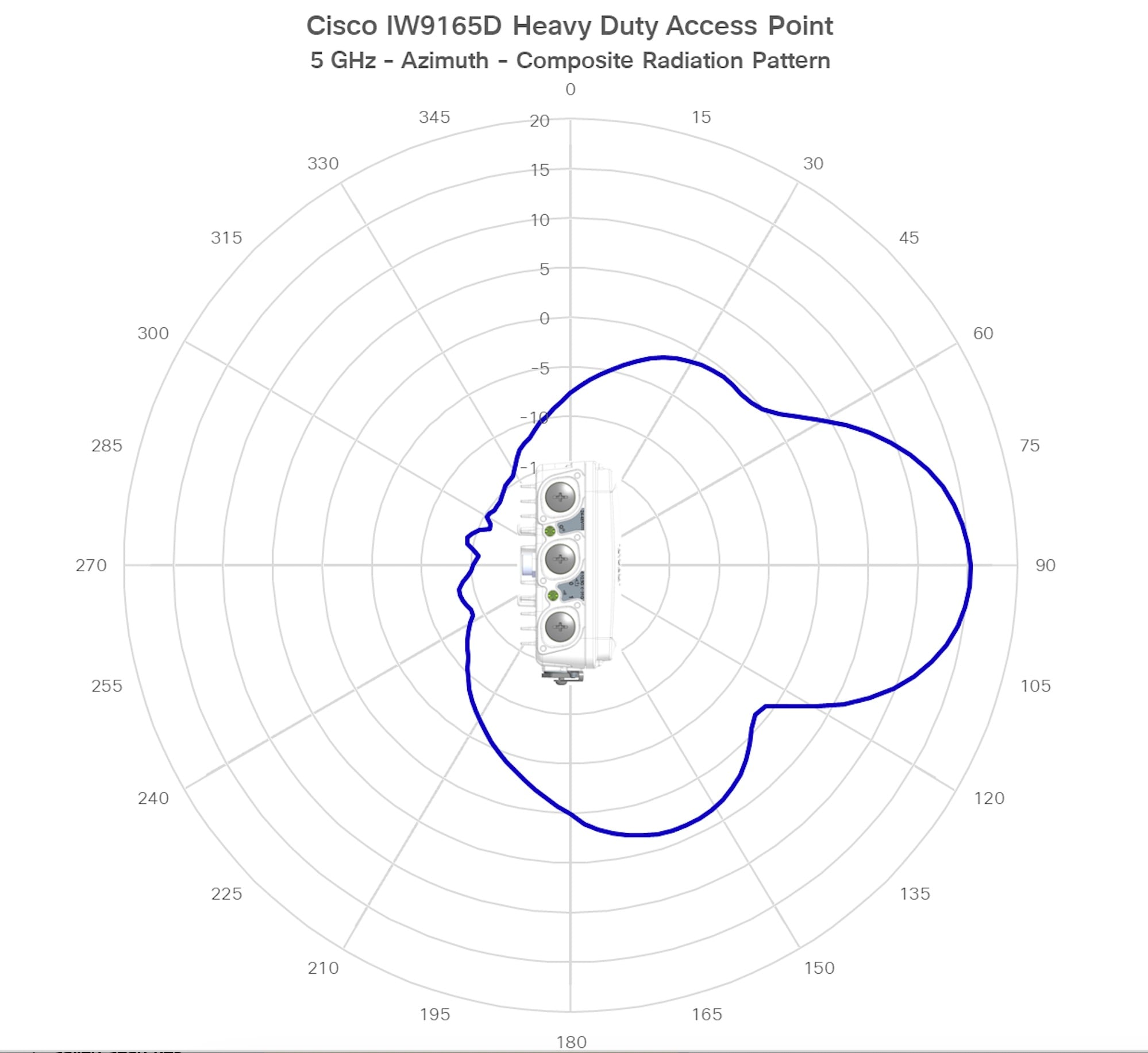
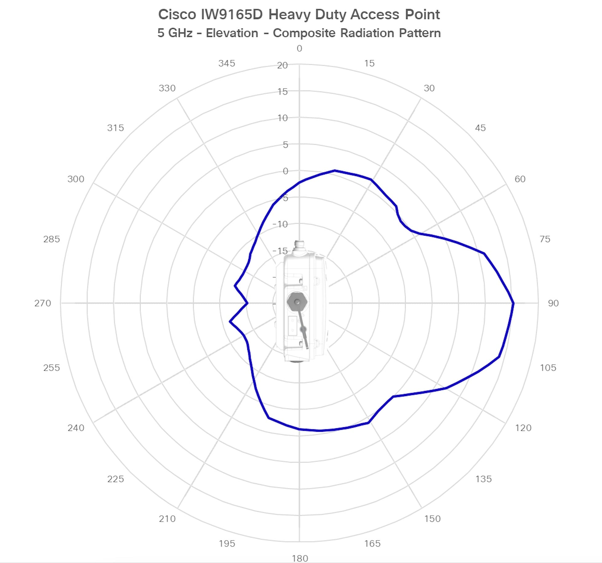
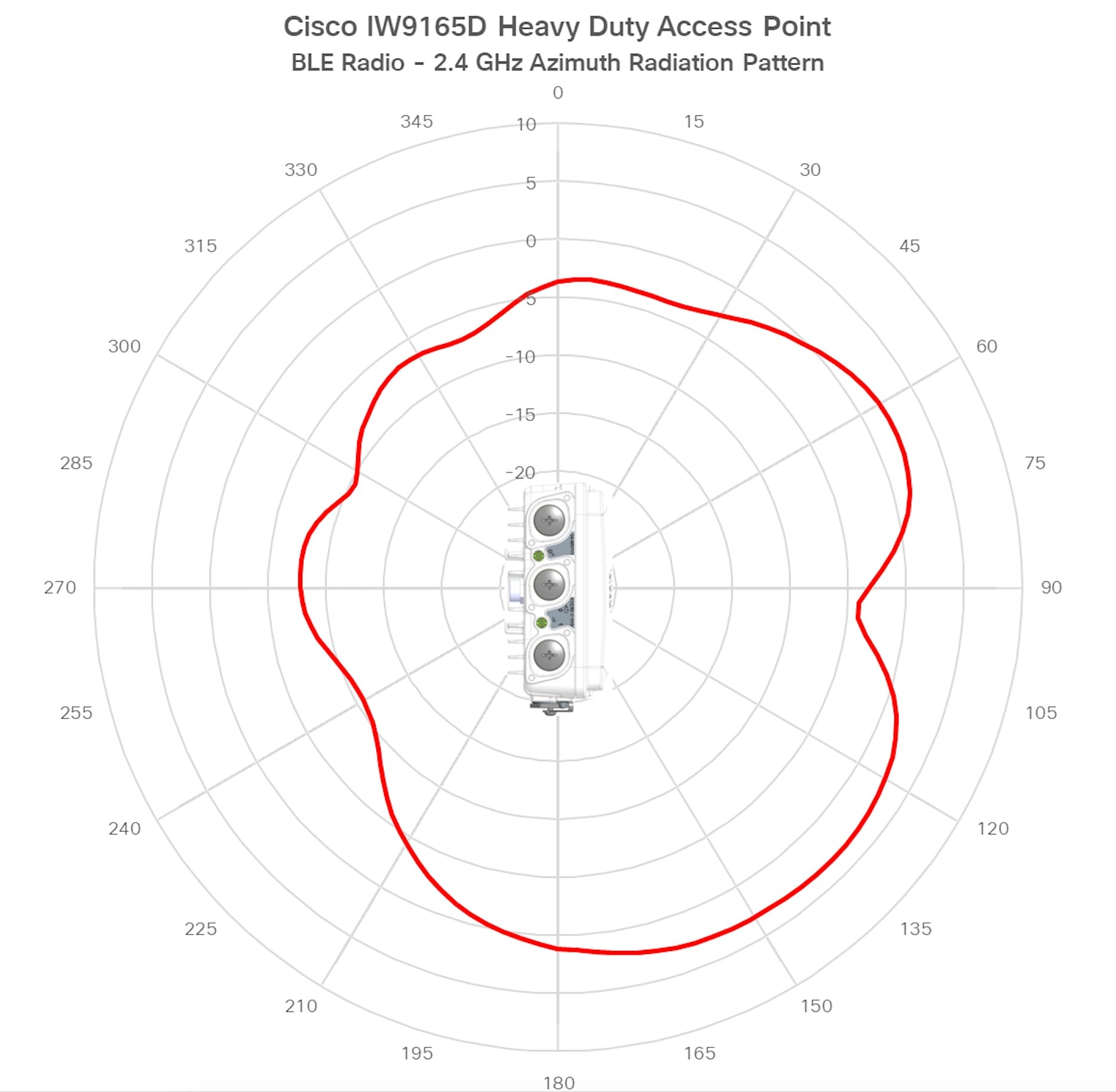
The following illustrations show the IW9165D model with internal antenna radiation patterns:

Table 5. Cisco Catalyst IW9165D Radiation Patterns
Figure 8. IW9165D - Composite Radiation Pattern (5-GHz Azimuth)
Figure 9. IW9165D - Composite Radiation Pattern (5-GHz Elevation)
Figure 10. IW9165D - IoT (BLE) Antenna - Radiation Pattern (2.4-GHz Azimuth)
Figure 11. IW9165D - IoT (BLE) Antenna - Radiation Pattern (2.4-GHz Elevation)