- Preface
- Chapter 1: Cisco MSE Virtual Appliance Overview
- Chapter 2: Cisco MSE Virtual Appliance Licensing
- Chapter 3: Installing the Cisco MSE Virtual Appliance on a VMware Virtual Machine
- Chapter 4: Installing the Cisco MSE Virtual Appliance on a XenServer
- Chapter 5: Installing the Cisco MSE Virtual Appliance on a Hyper-V Platform
- Appendix A: Virtual Machine Setup and Administration
- Appendix B: Command Reference
- Information About the Cisco MSE OVA
- Virtualization Concepts
- Overview of the Process for Installing the Cisco MSE Virtual Appliance on the VMware Virtual Machine
- Verifying Prerequisites
- Downloading the Cisco MSE Virtual Appliance OVA File
- Setting up the High End Virtual Appliance
- Deploying the Cisco MSE OVA File as an OVF Template
- Configuring the Basic Settings to Start the MSE Virtual Appliance VM
- Configuring MSE on the Prime Infrastructure
- Synchronizing the Network Designs
Installing the Cisco MSE Virtual Appliance on the VMware Virtual Machine
This chapter describes how to install the Cisco Mobility Services Engine (MSE) Open Virtual Appliance (OVA) components and includes the following sections:
Information About the Cisco MSE OVA
An Open Virtual Appliance (OVA) is a prebuilt software solution that comprises one or more virtual machines (VMs) that are packaged, maintained, updated, and managed as a single unit.
Virtualization Concepts
Refer to these documents for information on virtualization:
- https://www.vmware.com/pdfvirtualization.pdf
- Virtualization Basics
- Setting Up ESXi
Overview of the Process for Installing the Cisco MSE Virtual Appliance on the VMware Virtual Machine
Table 3-1 describes the steps to be followed while deploying the Cisco Mobility Services Engine (MSE) virtual appliance.
|
|
|
|---|---|
1. |
See the Verifying Prerequisites for more information. |
See the Downloading the Cisco MSE Virtual Appliance OVA File for more information. |
|
See the Setting up the High End Virtual Appliance for more information. |
|
4. A step-by-step template in the VSphere Client guides you through this process. After you have completed the step-by-step template, you can review all of the information that you provided, make any corrections, and then deploy the OVA. |
See the Deploying the Cisco MSE OVA File as an OVF Template for more information. |
See the Configuring the Basic Settings to Start the MSE Virtual Appliance VM for more information. |
|
See the Configuring MSE on the Prime Infrastructure for more information. |
|
See Synchronizing the Network Designs for more information. |
Verifying Prerequisites
Before installing the Mobility Services Engine (MSE) in a virtual machine, you must ensure the following:
- Latest version of VMware ESX/ESXi is installed and configured on the machine you plan to use as the MSE server host. See the VMware documentation for information on setting up and configuring your host machine.
- The installed VMware ESXi host is reachable.
- You can use the latest version of vSphere Client to manage the small deployments.
- Latest version of vCenter Server is installed on a Windows host in order to manage the ESXi hosts.
Downloading the Cisco MSE Virtual Appliance OVA File
The Mobility Services Engine (MSE) Open Virtualization Archive (OVA) is saved to the same machine where your vSphere Client or vCenter server is installed.
To download the.ova file, follow these steps:
Step 1![]() Access the Cisco MSE Virtual Appliance image at the following location: http://software.cisco.com/download/navigator.html.
Access the Cisco MSE Virtual Appliance image at the following location: http://software.cisco.com/download/navigator.html.
Step 2![]() In the Product/Technology Support section, choose Download Software.
In the Product/Technology Support section, choose Download Software.
Step 3![]() In the Select a Product section, navigate to the Wireless software by choosing Products > Wireless > Mobility Services > Cisco Mobility Services Engine Virtual Appliance.
In the Select a Product section, navigate to the Wireless software by choosing Products > Wireless > Mobility Services > Cisco Mobility Services Engine Virtual Appliance.
A list of the latest release software for Cisco Mobility Services Engine Virtual Appliance is available for download.
Step 4![]() In the Latest list, choose 7.6.100.0 or the latest 7.6 Release version to download.
In the Latest list, choose 7.6.100.0 or the latest 7.6 Release version to download.
Step 5![]() You can select any of the following ova files to download:
You can select any of the following ova files to download:
- MSE-VA-8-0-x-x.ova—Use this file to deploy MSE on a medium and high end VMware ESXi machine. This OVA is configured by default for the standard appliance. You need to make some modifications for OVA to work as high end appliance. See Setting up the High End Virtual Appliance for more information.
- MSE-VA-8-0-x-x-LowEnd.ova—Use this file to deploy MSE on a low end VMware ESXi machine.
Step 6![]() Save the installer to your computer in a place that will be easy to find when you start to deploy the OVF template.
Save the installer to your computer in a place that will be easy to find when you start to deploy the OVF template.
Setting up the High End Virtual Appliance
Use the MSE-VA-8-0-x-x.ova file to deploy both the medium and high end virtual appliance.
To setup the installed standard ova as high end ova, follow these steps:
Step 1![]() Follow the steps given in Deploying the Cisco MSE OVA File as an OVF Template to deploy the OVA file.
Follow the steps given in Deploying the Cisco MSE OVA File as an OVF Template to deploy the OVA file.
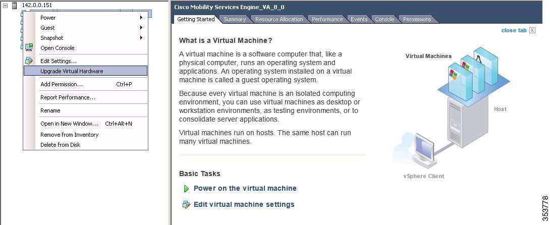
Step 2![]() You must upgrade the virtual hardware on the latest ESXi server while the Virtual Machine (VM) is powered off before increasing the CPU count. To assign more than 8 cores to the Virtual Appliance, you need to upgrade the virtual hardware. See Figure 3-1.
You must upgrade the virtual hardware on the latest ESXi server while the Virtual Machine (VM) is powered off before increasing the CPU count. To assign more than 8 cores to the Virtual Appliance, you need to upgrade the virtual hardware. See Figure 3-1.
Figure 3-1 Upgrade Virtual Hardware
Step 3![]() Edit the memory allocation and ensure that proper resources are assigned. See Table 3-2 .
Edit the memory allocation and ensure that proper resources are assigned. See Table 3-2 .

Note![]() These levels are configurable on the virtual appliance and corresponding requirements. Allocate dedicated cores to the appliance and not hyper threaded virtual cores. The performance is affected if you assume host has more virtual cores and deploy more appliances.
These levels are configurable on the virtual appliance and corresponding requirements. Allocate dedicated cores to the appliance and not hyper threaded virtual cores. The performance is affected if you assume host has more virtual cores and deploy more appliances.
|
|
|
|
||
|---|---|---|---|---|
|
|
|
|
|
|
Deploying the Cisco MSE OVA File as an OVF Template
The Mobility Services Engine (MSE) virtual appliance is distributed as n Open Virtualization Archive (OVA) file. The OVA is a single file distribution of an OVF package as an TAR format. After you download the OVA file, you will deploy the Open Virtualization Format (OVF) template from the vSphere Client application.
Note![]() Make sure that all of the system requirements are met before you deploy the OVA. Review the Verifying Prerequisites.
Make sure that all of the system requirements are met before you deploy the OVA. Review the Verifying Prerequisites.
Note![]() After a fresh OVA deployment, you must reboot the Virtual Machine (VM) once.
After a fresh OVA deployment, you must reboot the Virtual Machine (VM) once.
Step 1![]() Open the VMware VSphere Client application on your desktop.
Open the VMware VSphere Client application on your desktop.
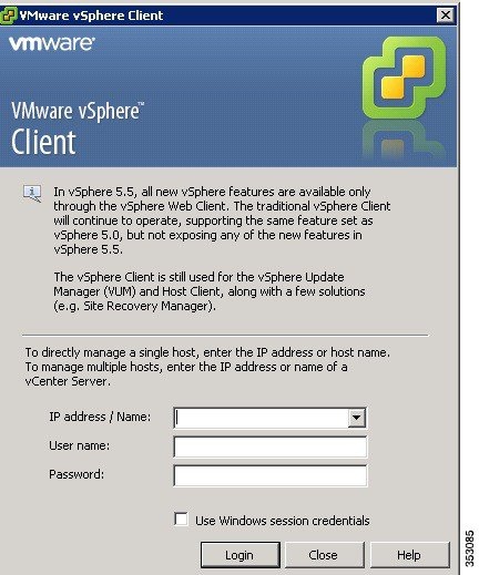
Step 2![]() Log in to your VSphere Client or VCenter Server (see Figure 3-2).
Log in to your VSphere Client or VCenter Server (see Figure 3-2).
Figure 3-2 VMware VSphere Client
Step 3![]() Use the vSphere Client to access the OVF template:
Use the vSphere Client to access the OVF template:
a.![]() Choose Home > Inventory > Hosts and Clusters.
Choose Home > Inventory > Hosts and Clusters.
b.![]() Choose the host on which the OVF template will be deployed.
Choose the host on which the OVF template will be deployed.
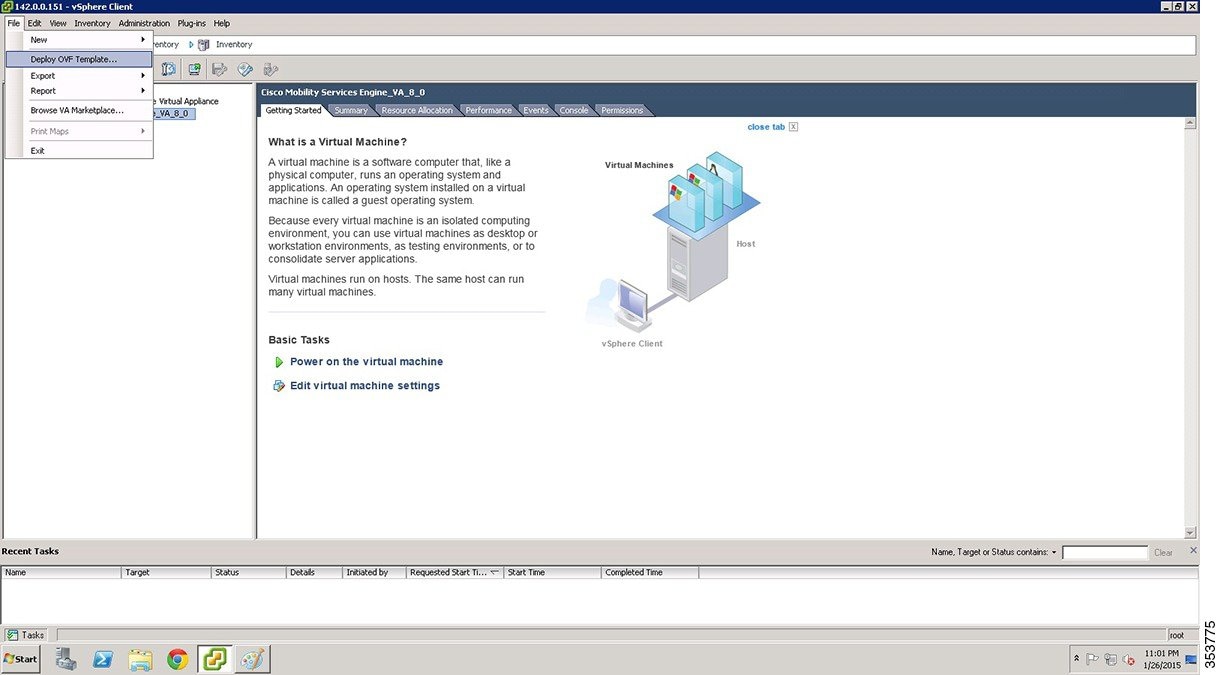
c.![]() Choose File > Deploy OVF Template from VSphere toolbar bar.
Choose File > Deploy OVF Template from VSphere toolbar bar.
The Deploy OVF Template dialog box appears (see Figure 3-3).
Figure 3-3 Deploy OVF Template
Step 4![]() Choose the Source location (see Figure 3-4).
Choose the Source location (see Figure 3-4).
a.![]() Click Browse. The Open dialog box opens.
Click Browse. The Open dialog box opens.
b.![]() From the Open dialog box, locate the appropriate.ova file that you downloaded to your computer and click Open.
From the Open dialog box, locate the appropriate.ova file that you downloaded to your computer and click Open.
Figure 3-4 Deploy From a File or URL
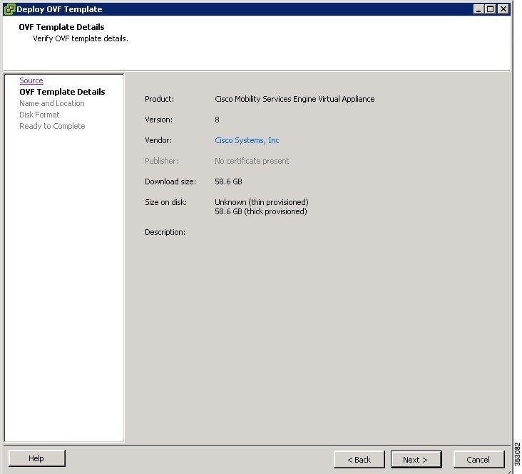
The OVF template details window appears (see Figure 3-5).
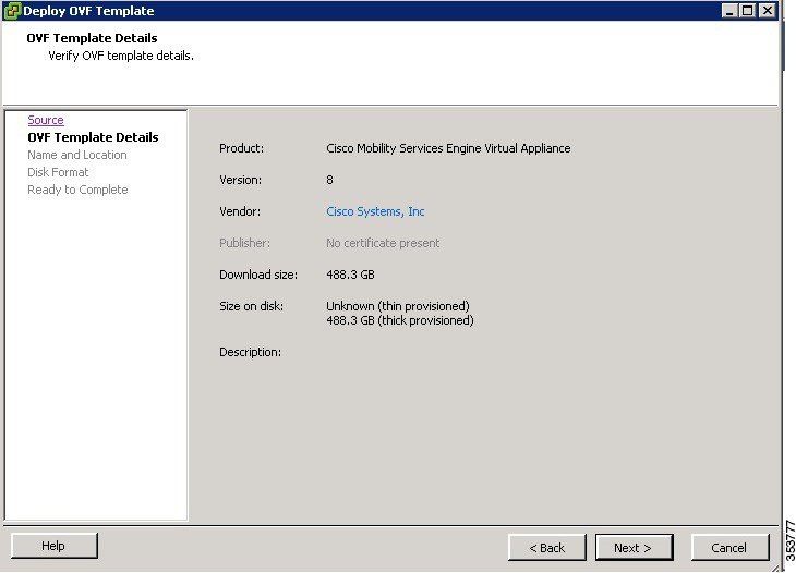
Step 6![]() Review the OVF template details. Some of the details about the Cisco MSE virtual appliance include:
Review the OVF template details. Some of the details about the Cisco MSE virtual appliance include:
–![]() Thin provision for the amount of disk space consumed by the virtual appliance immediately after deployment. It is the minimum amount of disk space needed to deploy the virtual appliance.
Thin provision for the amount of disk space consumed by the virtual appliance immediately after deployment. It is the minimum amount of disk space needed to deploy the virtual appliance.
–![]() Thick provision for the maximum amount of disk space the virtual appliance can consume.
Thick provision for the maximum amount of disk space the virtual appliance can consume.
Note![]() For more information on thick and thin provision, see “Step 10” task.
For more information on thick and thin provision, see “Step 10” task.
Figure 3-5 Review OVF Template Details
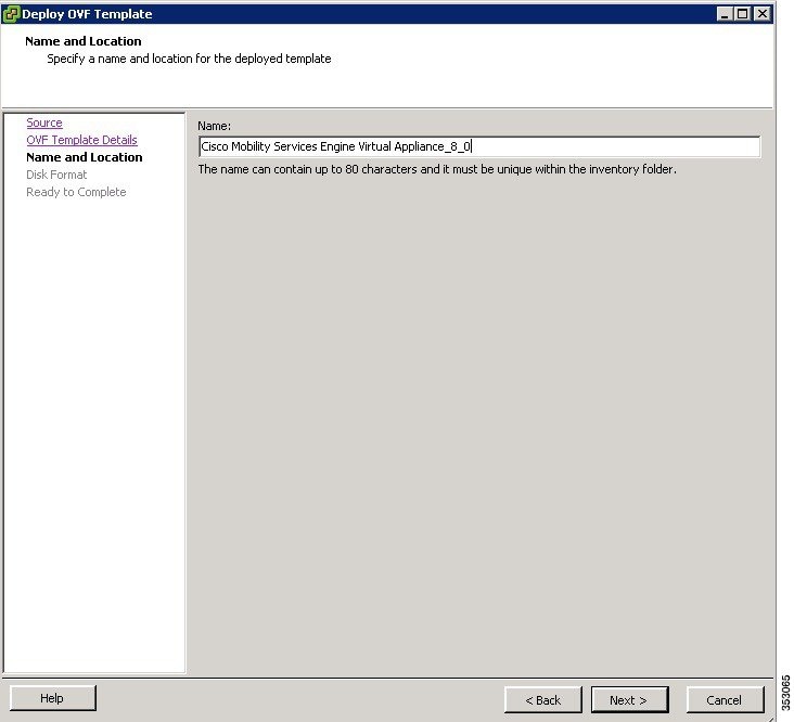
Step 7![]() Click Next. The Name and Location window appears (see Figure 3-6).
Click Next. The Name and Location window appears (see Figure 3-6).
Step 8![]() In the Name field, enter a template name for the new virtual appliance. If you are using the vCenter to manage the virtual machine, then you will have the option of selecting the location of the inventory.
In the Name field, enter a template name for the new virtual appliance. If you are using the vCenter to manage the virtual machine, then you will have the option of selecting the location of the inventory.
Figure 3-6 Name and Location Window
Step 9![]() Click Next. The Disk Format window appears.
Click Next. The Disk Format window appears.
Step 10![]() Choose the disk format:
Choose the disk format:
- Choose one of the thick provision types if you have enough storage capacity as required by the virtual appliance and want to set a specific allocation of space for the virtual disk.
–![]() Thick Provision Lazy Zeroed—The space that is required for the virtual disk is allocated when the virtual disk is created. The data that remains on the physical device is not erased when the virtual disk is created but is zeroed out on demand at a later time on first write from the virtual disk.
Thick Provision Lazy Zeroed—The space that is required for the virtual disk is allocated when the virtual disk is created. The data that remains on the physical device is not erased when the virtual disk is created but is zeroed out on demand at a later time on first write from the virtual disk.
–![]() Thick Provision Eager Zeroed—The space that is required for the virtual disk is allocated when the virtual disk is create. Unlike the Lazy Zeroed option, the data that remains on the physical device is erased when the virtual disk is created.
Thick Provision Eager Zeroed—The space that is required for the virtual disk is allocated when the virtual disk is create. Unlike the Lazy Zeroed option, the data that remains on the physical device is erased when the virtual disk is created.
- Thin Provision—Unlike with the thick format, space required for the virtual disk is not allocated during creation, but is supplied, zeroed out, on demand at a later time.
Step 11![]() Click Next. The Network Mapping window appears.
Click Next. The Network Mapping window appears.
Step 12![]() For each network specified in the OVF template, select a network by right-clicking the Destination Network column in your infrastructure to set up the network mapping.
For each network specified in the OVF template, select a network by right-clicking the Destination Network column in your infrastructure to set up the network mapping.
The Ready to Complete window appears (see Figure 3-7).
Step 14![]() Review each of the deployment settings that you have established (see Figure 3-7).
Review each of the deployment settings that you have established (see Figure 3-7).
Figure 3-7 Ready to Complete Window
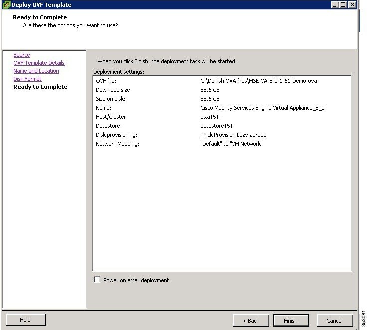
Step 15![]() Press Back to make any changes to the settings and click Finish to complete the deployment.
Press Back to make any changes to the settings and click Finish to complete the deployment.
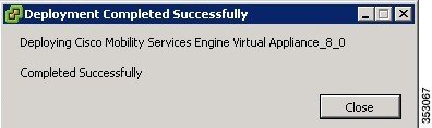
A progress bar keeps pace with your Cisco MSE virtual appliance deployment, which can take from 5 to 10 minutes to finish depending on the network latency (see Figure 3-8). When the deployment is finished, the Deployment Completed Successfully dialog box opens.
Figure 3-8 Deploying Dialog Box
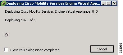
Step 16![]() Click Close to dismiss the dialog box.
Click Close to dismiss the dialog box.
Figure 3-9 Deployment Completed Successfully Dialog Box
Step 17![]() On the Summary tab in the VSphere Client, review the information about the Virtual Machine.
On the Summary tab in the VSphere Client, review the information about the Virtual Machine.
Step 18![]() The virtual appliance that you deployed is listed under the host, in the left pane of the VSphere Client.
The virtual appliance that you deployed is listed under the host, in the left pane of the VSphere Client.
Step 19![]() Edit the MSE virtual appliance template to map the management and data interfaces network interfaces to the desired configuration before powering up the MSE virtual appliance.
Edit the MSE virtual appliance template to map the management and data interfaces network interfaces to the desired configuration before powering up the MSE virtual appliance.
Step 20![]() Proceed with installing and configuring the MSE. See Configuring the Basic Settings to Start the MSE Virtual Appliance VM for more information.
Proceed with installing and configuring the MSE. See Configuring the Basic Settings to Start the MSE Virtual Appliance VM for more information.
Configuring the Basic Settings to Start the MSE Virtual Appliance VM
You have completed deploying the Mobility Services Engine (MSE) virtual appliance on a new virtual machine. A node for the virtual machine now appears in the resource tree in the VMware VSphere Client window. After deployment, you need to configure basic settings for the MSE virtual appliance.
To start the MSE setup, follow these steps:
Step 1![]() In the VSphere Client, click the MSE virtual appliance node in the resource tree. The virtual machine node should appear in the Hosts and Clusters tree below the host, cluster, or resource pool to which you deployed the MSE virtual appliance.
In the VSphere Client, click the MSE virtual appliance node in the resource tree. The virtual machine node should appear in the Hosts and Clusters tree below the host, cluster, or resource pool to which you deployed the MSE virtual appliance.
Step 2![]() If you have not powered on the virtual machine while deploying the OVA file, then right-click on the virtual appliance that is listed in the left pane of the VSphere Client, and choose Power > Power on.
If you have not powered on the virtual machine while deploying the OVA file, then right-click on the virtual appliance that is listed in the left pane of the VSphere Client, and choose Power > Power on.
The Recent Tasks window at the bottom of the VSphere Client pane indicates the status of the task associated with powering on the virtual machine. After the virtual machine successfully starts, the status column for the task shows Completed.
Step 3![]() Click the Console tab, within the console pane to make the console prompt active for keyboard input. The VM starts booting.
Click the Console tab, within the console pane to make the console prompt active for keyboard input. The VM starts booting.
Step 4![]() Press Enter for the login prompt to appear to initiate the MSE Installation Wizard. The following is displayed:
Press Enter for the login prompt to appear to initiate the MSE Installation Wizard. The following is displayed:
Note![]() The installation process takes approximately 45 minutes to complete.
The installation process takes approximately 45 minutes to complete.
Note![]() After the initial installation, you are logged off the newly created VM and you must login to the console panel again.
After the initial installation, you are logged off the newly created VM and you must login to the console panel again.
Step 5![]() The MSE virtual machine shuts down and reboots.
The MSE virtual machine shuts down and reboots.
[Configuration starts as soon as you log in]
[Press Enter to use the default values (yes) to use the Menu options]
Note![]() It is highly recommended that all relevant items be configured during initial setup to ensure optimum operation of the mobility services engine in your network. The hostname and either the Ethernet-0 (eth0) or the Ethernet-1 (eth1) port must always be configured during the automatic installation.
It is highly recommended that all relevant items be configured during initial setup to ensure optimum operation of the mobility services engine in your network. The hostname and either the Ethernet-0 (eth0) or the Ethernet-1 (eth1) port must always be configured during the automatic installation.
Note![]() You can rerun the automatic installation script at any time to add or change parameters using this command:
You can rerun the automatic installation script at any time to add or change parameters using this command:
[root@mse]# /opt/mse/setup/setup.sh.
There is no need to re-enter values that you do not want to change during one of these updates.
Note![]() If you do not want to configure an item, enter skip and you are prompted for the next configuration step. Any setting skipped is retained and not modified.
If you do not want to configure an item, enter skip and you are prompted for the next configuration step. Any setting skipped is retained and not modified.
Note![]() Minimal configuration is done for the mobility services engine as part of installation using the console. All configurations beyond the initial setup using the automatic installation is done with the Cisco Prime Infrastructure.
Minimal configuration is done for the mobility services engine as part of installation using the console. All configurations beyond the initial setup using the automatic installation is done with the Cisco Prime Infrastructure.
Step 7![]() Configure the hostname.
Configure the hostname.
Step 8![]() Configure eth0 network settings.
Configure eth0 network settings.
Step 9![]() Configure the DNS Settings.
Configure the DNS Settings.
Step 10![]() Configure the Timezone settings.
Configure the Timezone settings.
Note![]() If your wIPS deployment consists of a Cisco MSE and other devices (such as Cisco WLCs and access points), set the Cisco MSE and the other devices to the same time zone.
If your wIPS deployment consists of a Cisco MSE and other devices (such as Cisco WLCs and access points), set the Cisco MSE and the other devices to the same time zone.
Step 11![]() Configure the Root password.
Configure the Root password.
Note![]() If you do not set the root password, a warning message is displayed when you apply the settings.
If you do not set the root password, a warning message is displayed when you apply the settings.
Step 12![]() Configure the NTP Setup.
Configure the NTP Setup.
Step 13![]() Configure the Prime Infrastructure password.
Configure the Prime Infrastructure password.
Note![]() If you do not set the password, a warning message appears when you apply the settings. The default PI communication password is admin.
If you do not set the password, a warning message appears when you apply the settings. The default PI communication password is admin.
Step 14![]() Verify the setup information and apply the changes.
Verify the setup information and apply the changes.
Note![]() The next time you log in using root, only the Linux shell prompt appears and not the setup script. You can rerun the setup script at any time to change settings by logging in as root and running /opt/mse/setup/setup.sh.
The next time you log in using root, only the Linux shell prompt appears and not the setup script. You can rerun the setup script at any time to change settings by logging in as root and running /opt/mse/setup/setup.sh.
Step 15![]() Log in and configure the MSE to automatically launch after boot up.
Log in and configure the MSE to automatically launch after boot up.
Step 16![]() To configure the MSE to automatically launch after boot up, enter the following command:
To configure the MSE to automatically launch after boot up, enter the following command:
Step 17![]() Reboot using the following command:
Reboot using the following command:
Note![]() To start the MSE service manually, enter the following command:
To start the MSE service manually, enter the following command:
[root@mse8-0]# service msed start
The setup script generates a log file that can be found at /opt/mse/setup/setup.log.
Configuring MSE on the Prime Infrastructure
To configure the Mobility Services Engine (MSE) virtual appliance on the Prime Infrastructure, follow these steps:
Step 1![]() Launch Mozilla Firefox 11.0 or 12.0 or Internet Explorer 8 or 9 with the Chrome plug-in releases or Google Chrome 19.0. The Internet Explorer versions below than 8 are not recommended.
Launch Mozilla Firefox 11.0 or 12.0 or Internet Explorer 8 or 9 with the Chrome plug-in releases or Google Chrome 19.0. The Internet Explorer versions below than 8 are not recommended.
Note![]() When you use Firefox to log in and access Prime Infrastructure for the first time, the Firefox web browser displays a warning stating that the site is untrustable. When Firefox displays this warning, follow the prompts to add a security exception and download the self-signed certificate from Prime Infrastructure server. After you complete this procedure, Firefox accepts Prime Infrastructure server as a trusted site both now and during all future login attempts.
When you use Firefox to log in and access Prime Infrastructure for the first time, the Firefox web browser displays a warning stating that the site is untrustable. When Firefox displays this warning, follow the prompts to add a security exception and download the self-signed certificate from Prime Infrastructure server. After you complete this procedure, Firefox accepts Prime Infrastructure server as a trusted site both now and during all future login attempts.
Step 2![]() In the address line of browser, enter https://pi-ip-address, where pi-ip-address is the IP address of the server on which you installed and started Prime Infrastructure. Prime Infrastructure uses interface displays the Login page.
In the address line of browser, enter https://pi-ip-address, where pi-ip-address is the IP address of the server on which you installed and started Prime Infrastructure. Prime Infrastructure uses interface displays the Login page.
Step 3![]() Enter the username. The default username is root.
Enter the username. The default username is root.
Step 4![]() Enter the root password you created during the PI setup and not the MSE setup and click Login.
Enter the root password you created during the PI setup and not the MSE setup and click Login.
Note![]() If any licensing problem occur, a message appears in an alert box. If you have an evaluation license, the number of days until the license expires is shown. You are also alerted to any expired licenses. You have the option to go directly to the licensing page to address these problem.
If any licensing problem occur, a message appears in an alert box. If you have an evaluation license, the number of days until the license expires is shown. You are also alerted to any expired licenses. You have the option to go directly to the licensing page to address these problem.
Step 5![]() Choose Services > Mobility Services Engines.
Choose Services > Mobility Services Engines.
Step 6![]() From the Select a command drop-down list, choose Add Mobility Services Engine. Click Go.
From the Select a command drop-down list, choose Add Mobility Services Engine. Click Go.
The Add Mobility Services Engine page appears.
Step 7![]() Enter the following information:
Enter the following information:
- Device Name—User-assigned name for the mobility services engine.
- IP Address—The IP address of the mobility services engine.
Note![]() A mobility services engine is added only if a valid IP address is entered. The Device Name helps you distinguish between devices if you have multiple Prime Infrastructures with multiple mobility services engines, but is not considered when validating a mobility services engine.
A mobility services engine is added only if a valid IP address is entered. The Device Name helps you distinguish between devices if you have multiple Prime Infrastructures with multiple mobility services engines, but is not considered when validating a mobility services engine.
- Contact Name (Optional)—The mobility service engine administrator.
- Username—The default username is admin. This is the Prime Infrastructure communication username configured for MSE.
- Password—The default password is admin. This is the Prime Infrastructure communication password configured for MSE.
Note![]() This refers to the Prime Infrastructure communication username and password created during the setup process.If you have not specified the username and password during the setup process, use the defaults. The default username and password are both admin.
This refers to the Prime Infrastructure communication username and password created during the setup process.If you have not specified the username and password during the setup process, use the defaults. The default username and password are both admin.
Step 8![]() Select the Delete synchronized service assignments check box if you want to permanently remove all service assignments from the mobility services engine.
Select the Delete synchronized service assignments check box if you want to permanently remove all service assignments from the mobility services engine.
This option is applicable for network designs, wired switches, controllers and event definitions. The existing location history data is retained, however, you must use manual service assignments to perform any future location calculations.
The MSE License Summary page appears (see Figure 3-10). You can use the MSE License Summary page to install a license, add a license, remove a license, install an activation license, and install service license.
Figure 3-10 MSE License Summary Page
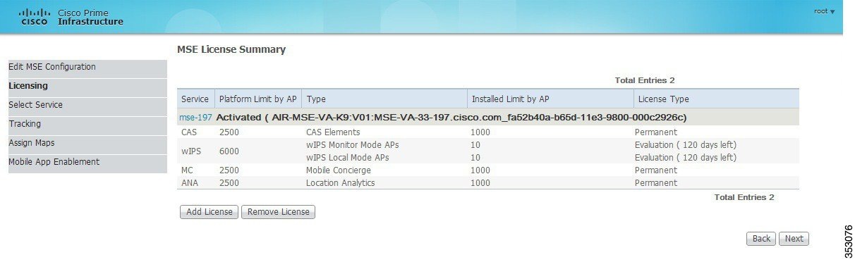
Step 10![]() Click Add License to add a license. You can install an activation license and service license.
Click Add License to add a license. You can install an activation license and service license.
The Add a License File dialog box appears.
Step 11![]() Click Choose File to browse to and select the license file.
Click Choose File to browse to and select the license file.
Step 12![]() Click OK to add the license. The newly added license appears in the MSE license file list.
Click OK to add the license. The newly added license appears in the MSE license file list.
Step 13![]() To remove an MSE license file, click Remove License.
To remove an MSE license file, click Remove License.
Step 14![]() Choose an MSE license file that you want to remove by selecting the MSE License File radio button, and click Remove.
Choose an MSE license file that you want to remove by selecting the MSE License File radio button, and click Remove.
Step 15![]() Click OK to confirm the deletion.
Click OK to confirm the deletion.
Step 16![]() Click Next to enable services on the mobility services engine.
Click Next to enable services on the mobility services engine.
Step 17![]() To enable a service, select the check box next to the service. These are the available services:
To enable a service, select the check box next to the service. These are the available services:
- Context Aware Service
- WIPS
- Mobile Concierge Service
- CMX Analytics
- CMX Browser Engage
- HTTP Proxy Service
Note![]() Select the services you need and for which you have the licenses. If you select CMX Analytics, you must also select the Context Aware Service.
Select the services you need and for which you have the licenses. If you select CMX Analytics, you must also select the Context Aware Service.
Step 18![]() Click Next. The Select Tracking & History Parameters page appears.
Click Next. The Select Tracking & History Parameters page appears.
Note![]() If you skip configuring the tracking parameters, the default values are selected.
If you skip configuring the tracking parameters, the default values are selected.
Step 19![]() You can select the clients to be tracked using the Prime Infrastructure by selecting the corresponding Tracking check box(es). Make sure that wireless clients are tracked.
You can select the clients to be tracked using the Prime Infrastructure by selecting the corresponding Tracking check box(es). Make sure that wireless clients are tracked.
The various tracking parameters are as follows:
Step 20![]() You can enable the history tracking of devices by selecting the corresponding devices check box(es). The different history parameters are as follows:
You can enable the history tracking of devices by selecting the corresponding devices check box(es). The different history parameters are as follows:
Step 21![]() Click Next to assign maps to the MSE and view your managed system on realistic campus, building, outdoor area, and floor maps.
Click Next to assign maps to the MSE and view your managed system on realistic campus, building, outdoor area, and floor maps.
Note![]() The Assigning Maps page is available only if you select Context Aware Service as one of the services to be enabled on the MSE.
The Assigning Maps page is available only if you select Context Aware Service as one of the services to be enabled on the MSE.
Table 3-3 lists the preset filters that are available in the Assigning Maps page. Choose the filter you want to show from the Show drop-down list.
|
|
|
|---|---|
In addition, you can use the filter icon ( ) to filter the maps that match the filter rules. If you want to specify a filter rule, choose All from the Show drop-down list before you click (
 ).
).
Step 22![]() To synchronize the map, select the Name check box and click Synchronize. Upon synchronization of the network designs, the appropriate controllers that have APs assigned on a particular network design are synchronized with the MSE automatically.
To synchronize the map, select the Name check box and click Synchronize. Upon synchronization of the network designs, the appropriate controllers that have APs assigned on a particular network design are synchronized with the MSE automatically.
Step 23![]() Click Next to configure the mobile application integration.
Click Next to configure the mobile application integration.
Step 24![]() Click Done in the Mobile App Enablement page.
Click Done in the Mobile App Enablement page.
Step 25![]() Click OK to save the MSE settings.
Click OK to save the MSE settings.
You must synchronize the network designs. See Synchronizing the Network Designs.
Synchronizing the Network Designs
Step 1![]() Choose Services > Synchronize Services.
Choose Services > Synchronize Services.
The Network Designs page appears. The left sidebar menu contains the following options: Network Designs, Controllers, Event Groups, Wired Switches, Third Party Elements, and Service Advertisements.
Step 2![]() From the left sidebar menu, choose the appropriate menu options.
From the left sidebar menu, choose the appropriate menu options.
Step 3![]() To assign a network design to a mobility services engine, in the Synchronize Services page, choose Network Designs from the left sidebar menu.
To assign a network design to a mobility services engine, in the Synchronize Services page, choose Network Designs from the left sidebar menu.
Step 4![]() Select the maps to be synchronized with the mobility services engine by selecting the corresponding Name check box.
Select the maps to be synchronized with the mobility services engine by selecting the corresponding Name check box.
Step 5![]() Click Change MSE Assignment.
Click Change MSE Assignment.
Step 6![]() Choose the mobility services engine to which the maps are to be synchronized.
Choose the mobility services engine to which the maps are to be synchronized.
Step 7![]() Click CAS in the Choose MSEs dialog box and click Synchronize.
Click CAS in the Choose MSEs dialog box and click Synchronize.
Step 8![]() Click Synchronize to update the mobility services engine(s) database(s).
Click Synchronize to update the mobility services engine(s) database(s).
When items are synchronized, a green two-arrow icon appears in the Sync. Status column for each synchronized entry. You can use the same procedure to assign wired switches or event groups to a mobility services engine.
Assigning an MSE to the Controller
Step 9![]() In the Network Designs page, choose Controller from the left sidebar menu.
In the Network Designs page, choose Controller from the left sidebar menu.
Step 10![]() Select the controllers to be assigned to the mobility services engine by selecting the corresponding Name check box.
Select the controllers to be assigned to the mobility services engine by selecting the corresponding Name check box.
Step 11![]() Click Change MSE Assignment.
Click Change MSE Assignment.
Step 12![]() Choose the mobility services engine to which the controllers must be synchronized.
Choose the mobility services engine to which the controllers must be synchronized.
Step 13![]() Click CAS in the Choose MSEs dialog box.
Click CAS in the Choose MSEs dialog box.
Step 14![]() Click Synchronize to complete the synchronization process.
Click Synchronize to complete the synchronization process.
Step 15![]() Verify that the mobility services engine is communicating with each of the controllers for only the chosen service. This can be done by clicking the NMSP status link in the status page.
Verify that the mobility services engine is communicating with each of the controllers for only the chosen service. This can be done by clicking the NMSP status link in the status page.
Note![]() After synchronizing a controller, verify that the timezone is set on the associated controller.
After synchronizing a controller, verify that the timezone is set on the associated controller.
Note![]() Controller names must be unique for synchronizing with a mobility services engine. If you have two controllers with the same name, only one is synchronized. You can use the same procedure to assign Catalyst switches or event groups to a mobility services engine.
Controller names must be unique for synchronizing with a mobility services engine. If you have two controllers with the same name, only one is synchronized. You can use the same procedure to assign Catalyst switches or event groups to a mobility services engine.
Checking the NMSP Connection Status
Step 16![]() Choose Services > Mobility Services Engine.
Choose Services > Mobility Services Engine.
Step 17![]() Click the name of the mobility services engine whose properties you want to view or edit.
Click the name of the mobility services engine whose properties you want to view or edit.
Step 18![]() Choose System > Status > NMSP Connection Status from the left sidebar menu.
Choose System > Status > NMSP Connection Status from the left sidebar menu.
Step 19![]() Check if NMSP is active under the Summary panel.
Check if NMSP is active under the Summary panel.
 Feedback