Choosing the Right Access Point
Understanding the Access Point Portfolio
Cisco-Aironet has many different model Access Points to choose from for just about any application. While this guide primarily focuses on the AP-4800 lets briefly examine the current portfolio.
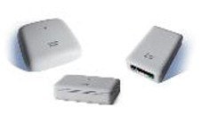
1815 Series
AP-1815i–Indoor Access Point for small to medium-sized business deployments
AP-1815m–Similar form, fit and function at AP-1815i but more transmit power to cover a larger area.
AP-1815w–Wall Plate for hotels, residential halls, hospitality and multi-dwelling unit deployments
AP-1815t–Targeted for teleworkers and micro-branch deployments
Feature includes:
-
2x2:2 SS 80 MHz
-
867 Mbps performance
-
Tx beamforming
-
Integrated BLE
-
Max transmit power (dBm) per local regulations
-
3 GE local ports, including 1 PoE out
-
Local ports 802.1X ready
-
USB 2.0
1830/1850 Series
Features include:
-
3x3:2 SS 80 MHz/4x4:3 SS 80 MHz
-
867 Mbps or 1.7 Gbps performance
-
1 or 2 GE ports uplink
-
Internal or external antenna (1850)
-
Tx beamforming
-
USB 2.0
The 1815, 1830 and 1850 Series are Good Enterprise Class Access Points but are able to function with older PoE powering systems such as 802.3af (15.4W) systems as they are not nearly as powerful as the better and best in class 2800, 3800 and 4800 Series which require 802.3at (30W) PoE systems.
2800 Series
Features include:
-
4x4:3 SS 160 MHz
-
5 Gbps performance
-
2.4 and 5 GHz or dual 5 GHz
-
2 GE ports uplink
-
Cisco CleanAir® and ClientLink
-
Internal or external antenna
-
Smart antenna connector
-
USB 2.0
The AP-2800 is a great all around Enterprise AP for mission critical applications, it is very similar to the AP-3800 however; the 2800 does not have a local DC port, Multigigabit port or Expandable Module port.
3800 Series
Features include:
-
4x4:3 SS 160 MHz
-
5 Gbps performance
-
2.4 and 5 GHz or dual 5 GHz
-
2 GE ports uplink or 1 GE + 1 Multigigabit (5G)
-
Cisco CleanAir and ClientLink
-
StadiumVision™
-
Internal or external antenna
-
Smart antenna connector
-
USB 2.0
-
Modularity for investment protection
4800 Series
Features include:
-
4 embedded radios (3 Wi-Fi and 1 BLE)
-
4x4:3 SS 160 MHz
-
5 Gbps performance
-
2.4 and 5 GHz or dual 5 GHz
-
2 GE ports uplink or 1 GE + 1 Multigigabit (5G)
-
Embedded Hyperlocation
-
Real-time analytics and packet capture
-
Cisco CleanAir and ClientLink
-
Internal antennas
-
USB 2.0
-
Integrated BLE–5 Dynamic Beacons
The 4800 series is indeed the best in class and most advanced Access Point.
Cisco-Aironet RF engineers have brought many innovative Access Point features that go beyond what can be found in the 802.11 specification. Some of these unique features are, ClientLink, CleanAir, Flexible Radio, and Hyperlocation – let’s quickly review these.
ClientLink
With the introduction of 802.11n, the IEEE standards body allowed for beamforming but unfortunately it was not implemented until the much later as the (802.11ac Wave-2) standards based beamforming was defined and clients and AP manufacturers adopted same for use with advanced features such as Multi-User MIMO. Note: Standards based beamforming only works when the Client is able to send CSI (Channel State Information to the AP)
While the AP-4800 also supports the standards based beforming, Client Link is a unique Cisco enhancement that allows for Access Point transmit beamforming (Tx-BF) this uses the additional transmitters to enhance the perception of the received signal at the client by forming the transmitted elements into a focused beam without the need for the client to send CSI. Better still ClientLink supports 802.11a,g,n and ac clients whereas the standards based only helps 802.11ac clients.
Note, the AP-4800 is a 4x4:3 Access Point meaning it has 4 transmitters, 4 Receivers and can do 3 Spatial Streams. (Why not 4-SS)? Because the AP-4800 uses ClientLink 4.0 to do 3-SS along with an additional antenna (N+1) that allows for beam-forming for all 802.11a/g/n and now ac clients including those supporting 3 spatial streams.
Given you need at least 1 more antenna (N+1) 4-SS is not practical as current clients do not support this it would have required the AP to have had 5 antennas in order to perform TxBF on a 4-ss signal.
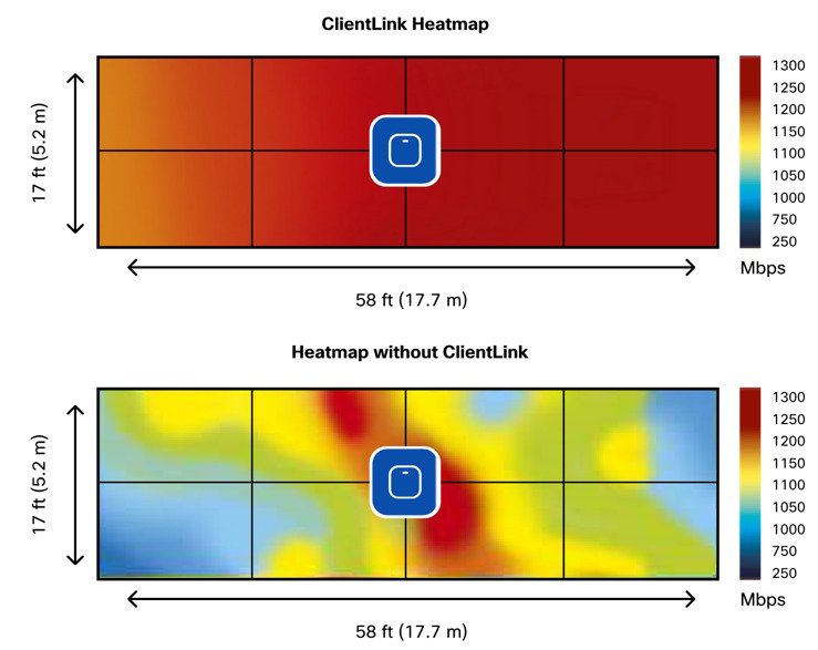
Client link improves the Signal-to-Noise Radio (SNR) in the downlink direction enabling the client to maintain a higher data rate longer with less retries. Figure below is an example of this advantage.
CleanAir Spectrum Analysis
Cisco CleanAir Technology: A Custom Hardware/Software Solution
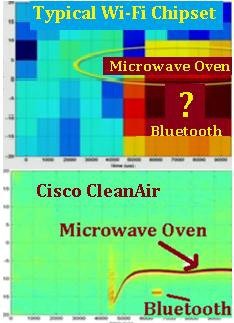
To overcome the visibility limitations inherent to standard Wi-Fi chipsets, Cisco has created an integrated solution with patented chips and software that has been specifically designed to analyze and classify all RF activity. (More than 25 patents have been issued for this technology to date). Essentially, Cisco has taken the technology behind the Cisco® Spectrum Expert analysis tool, and integrated it directly into the infrastructure, including deep integration within the Wi-Fi chipset. This is a significant development, and demonstrates that as wireless has transitioned from nice-to-have to business-critical in the enterprise.
The custom solution starts with the Cisco Spectrum Analysis Engine (SAgE) hardware core, which has been integrated directly into the Wi-Fi chipset of the 1600/2600/2700/3600/3700/3800 and 4800 Series of 802.11n/802.11ac capable Cisco Aironet® Access Points. The SAgE core handles very compute-intensive operations, such as high-resolution Fast Fourier Transform (FFT) and pulse detection operations. (A pulse is a burst of RF energy in frequency and time.) The SAgE core has a highly granular spectral resolution of 78.125 kHz (4x better than the nearest competitive solution and 64x better than most chipsets) which helps enable a broad interference detection and analysis. Essentially, the SAgE core handles a base level of spectrum analysis operations that are so processing-intensive they can be prohibitive to handle in real-time software.
For more on this see Appendix URL #1
CleanAir allows the Access Point to identify with high accuracy the type of interference, identifying make/model of interfering devices, and can identify all types of inferers even non Wi-Fi emissions.
Flexible Radio Assignment (FRA) and Dual 5 GHz Operations
FRA and Dual 5 GHz Operations
Managing a dual 5 GHz cells is one of the most important things that FRA does. There are two modes of operation for Dual 5 GHz AP's:
-
Macro/Micro–A large cell with a smaller cell internal – creating double the capacity within the boundaries of a single cell.
-
Macro/Macro–Dual- independent 5 GHz cells, doubling the coverage of a single traditional Dual Band AP. (Macro/Macro is only supported on 2800e and 3800e (as external antennas are used to accomplish this).
Macro/Micro is a use case applicable to the Cisco AP 3800/2800 I Models and the new AP-4800 only. The antennas on these APs are designed to support a Cell within a Cell deployment. In order for this to be effective, much design is committed to isolation of the two cells starting at the silicon level, and ending with separation in antenna polarity and frequency separation.
FRA and DCA will enforce many configuration requirements when operating as Dual 5 GHz Macro/Micro:
-
Minimum 100 MHz Channel Separation (Frequency Diversity)
-
Micro Cell Power is restricted to minimum
-
Same SSID’s on each cell
Having a Macro/Micro cell architecture is attractive because it solves the problem of having one large cell - in which a very diverse client experience exists. Clients closer to the AP are using higher data rates and enjoy a higher SNR than will clients at the edge of the cell. Macro Micro allows isolation of different clients within the cell that can serve them best and preserves airtime by increasing overall efficiency.

For more on Flexible Radio Assignment and Dual 5 GHz Operation see appendix URL #2
More details on this feature can be found in the Cisco Aironet 2800/3800 Deployment guide see appendix URL #3
Take-away
A dual 5 GHz capable AP-4800 creating Micro/Macro cells with the ability to beamform (using ClientLink) will significantly enhance all 802.11a,g,n and ac Wave-1 client performance.
When the 4800 Series is operating in Dual 5 GHz mode, clients get equal airtime, lower channel utilization rates, faster client connected data-rates and less retries.
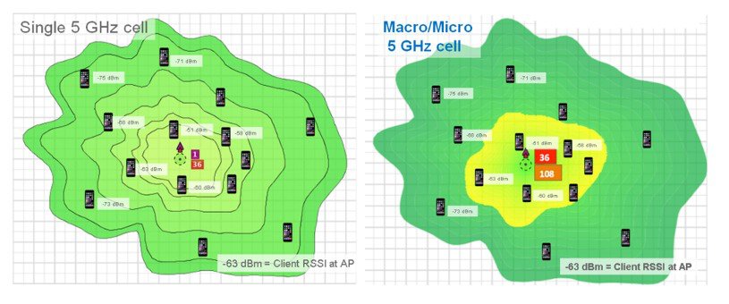
In the figure above, (on the left) a single channel cell say channel 36 has a channel utilization of 60% because all clients are connected to that one channel, to make matters worse they connect at non-uniform speeds as the close in clients connect much faster than the far away clients.
(Left) Single channel model–Utilization is at 60% on channel 36
(Right) Dual channel model–Channel 36 drops to 20% and Channel 108 is at 24%
Looking at the dual channel model (on the right) using two channels the improvements become clear. This results in far less contention and less retries and a far better user experience. Note: This feature was first introduced in the 2800/3800 series won Cisco’s Pioneer Award for innovation in 2017.
Hyperlocation – Pinpoint Location Accuracy
Cisco Hyperlocation delivers exceptional indoor location accuracy using your Cisco indoor Wi-Fi. Three Cisco technologies-the next-generation Hyperlocation Aironet 4800 access point, Connected Mobile Experiences (CMX) location engine, and CMX Location SDK-work together to enhance both accuracy and refresh rate for precision navigation, engagement, analytics and other location services.
Using Hyperlocation supporting fastLocate technology to generate frequency location updates for connected Wi-Fi clients along with integrated BLE beacons (up to 5 beacons) provide extremely fast (near real-time refresh) when the Cisco CMX SDK is embedded in your mobile application.
Potential use cases:
-
Wayfinding – Geo-fencing
-
Navigation / Asset Tracking
-
Interactive kiosks; Gaming
-
Digital Advertising
-
Customer Loyalty/Coupons
-
Safety / Security access
-
Patient / People tracking
-
Airports to optimize security checkpoints / people flow
Using Cisco DNA center and Cisco’s Intelligent Packet Capture feature allows for a one view packet capture. This is accomplished by simultaneously using CleanAir to show interference, channel quality, Hyperlocation to display client’s location while stitching this along with the roam between Access point for a true Intelligent Capture in one view.
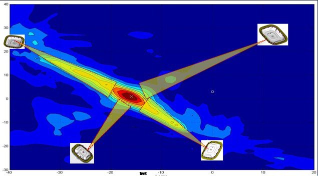
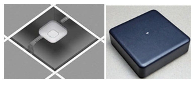
Note: when mounting the units to the ceiling grid, it is recommended that you orientate all of the Access Points in the same direction. This will make it easier when recording them. If you are not mounting to the ceiling rails, use a laser pointer or other device to try and align them in the same direction.
Oftentimes, it is difficult to measure and map the location when the AP4800 unit is mounted high on a ceiling. In these cases, it is suggested that the use of a Plumb Bob dropped from the center of the AP or a laser pointer be used to mark the exact location on the floor so that a tape measure or laser range finder can be used.
For more on Hyperlocation see the overview in the appendix URL #4
For more on Hyperlocation see the deployment guide in the appendix URL #5
Minimum Hardware and Software Requirements for Hyperlocation
-
Cisco Prime 3.4 or higher
-
Cisco CMX 10.5 or higher
-
Cisco WLC code 8.7S (8.7.106.0) or higher
-
Have an NTP server (application or router running on same subnet as Prime, WLC and CMX with all three syncing up to the same NTP server)
-
If you do not have an NTP server, the standalone NTP server which can be accessed using the following link was tested ad-hoc with good success on Windows:
-
Another server that can be used https:// time.nist.gov
-
4800 Series Access Point Physicals and Mounting Options
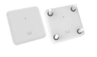
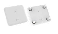
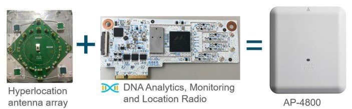
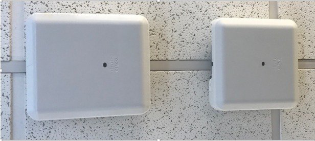
While similar to the AP-3800i the 4800 Series Access Point is far more advanced and slightly larger in size this is due to the additional enhancements which include: Hyperlocation Antenna Array, Embedded Analytics/Location radio and Bluetooth Low Energy radio for beacons all embedded within the AP-4800.
4800 Series Physical Dimensions
AP-4800 dimensions and Weight
Length - 9.9 inches (251.48mm)
Width - 8.68 inches (220.47mm)
Thickness – 2.87 inches (72.9mm)
Weight 5.6 pounds (2.54 kilograms)*
 Note |
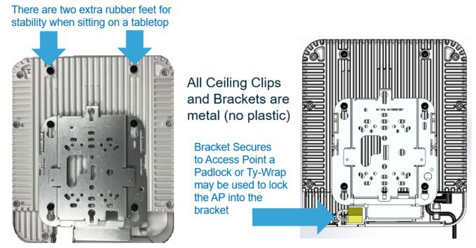
*While the 4800 Series AP is one pound heavier (0.45 kilograms) this is not a concern as the typical ceiling grid work (ceiling rails) are designed to hold weights up to 25 pounds (11.34 kilograms) without a suspension wire attached behind the grid rail (worse case) and can hold even greater weight if a support wire is used. Given all the bracketry is metal and the ceiling rail is metal there is no danger of the Access Point falling or causing any issues due to weight provided a plastic tie or clip is used on the AP to secure it into the bracket. |
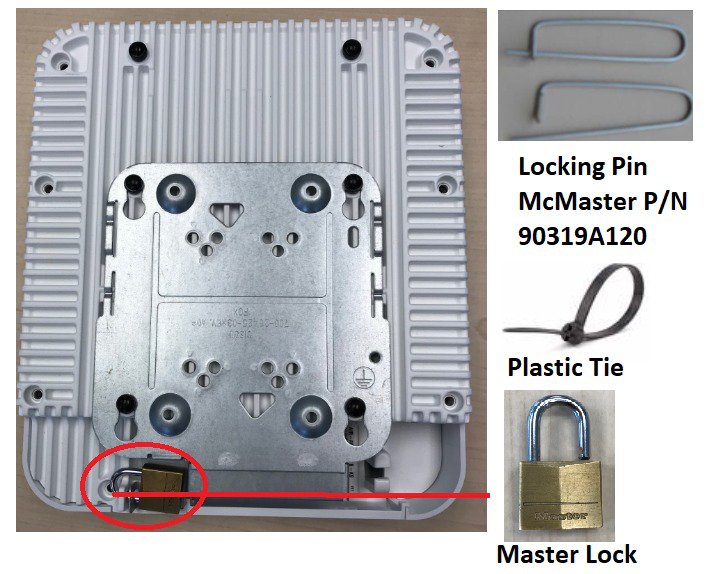
The AP-4800 has a small metal detent in the bracket that allows for a positive lock into the bracket. However; in areas of high vibration or where the potential exists that the AP could be physically impacted (example, someone carrying a ladder strikes it) it is recommended that a Clip, Plastic tie or lock be used, this prevents any sort of physical contact that might release the AP from the bracket causing it to fall.
In-ceiling Brackets
Deployments where aesthetics and/or perceived weight concerns are an issue, third party companies make available many mounting options to address this concern.
Mounting above the ceiling should be discouraged unless that is the only option as it can diminish the WLAN coverage cell and/or degrade location capabilities. Never mount the AP above the ceiling if the area is cluttered with other metal duct work, boxes etc.
The following 3rd party companies are recommended for different types of mounting solutions.
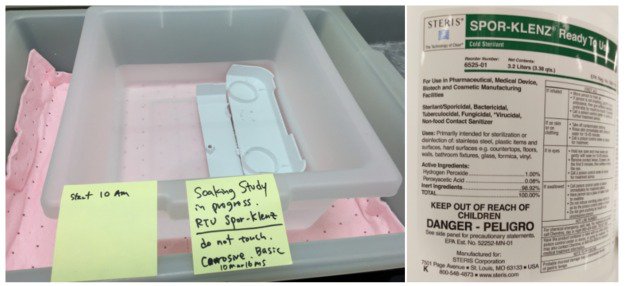
If the AP-4800 is used in a clean room, hospital or other areas where the need for infection control requires the Access Point to be wiped down with a chemical, it is recommended that Steris “Spor-Klenz be used. Unlike some Access Points the AP-4800 does not have vent holes in the construction so it may be wiped down and the plastics have been tested with this material.
4800 Series Mounting Brackets
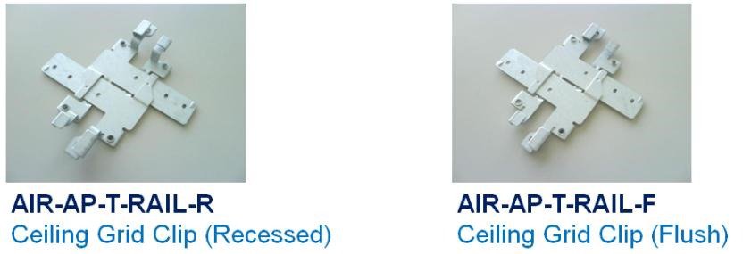
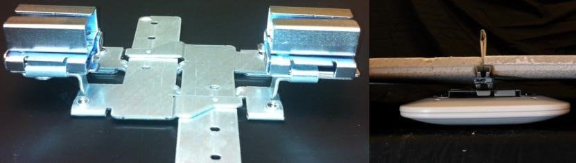
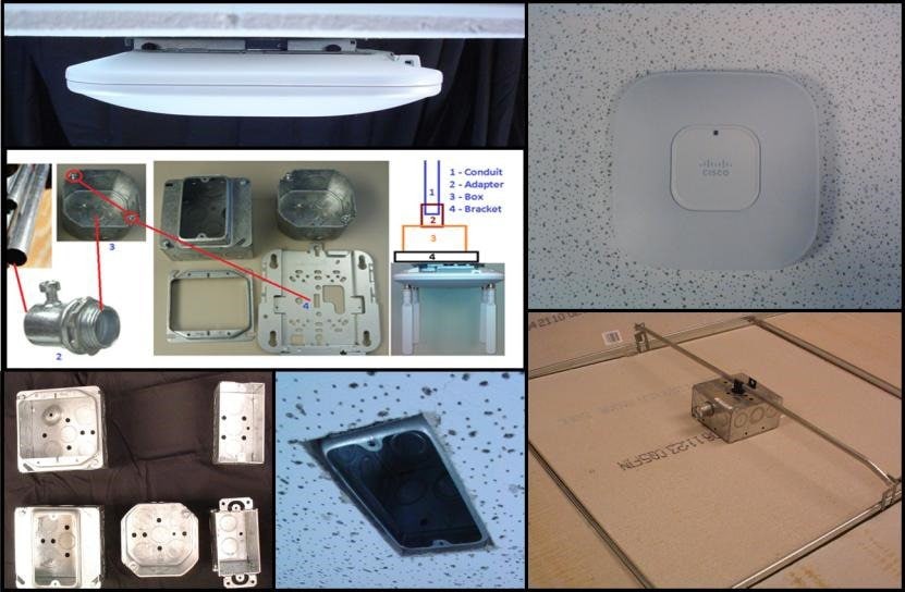
There are many different installation options available depending upon the requirements of the customer. Brackets are available from Cisco as well as third-party companies. During the ordering process, the customer may choose one of two brackets (but not both). Each bracket is a zero-dollar ($0) option at the time of configuration. If the customer does not choose a bracket, the selection default is AIR-AP-BRACKET-1 which is the most popular for ceiling installations. The other choice is a universal bracket that carries part number AIR-AP-BRACKET-2 (Figure 16).
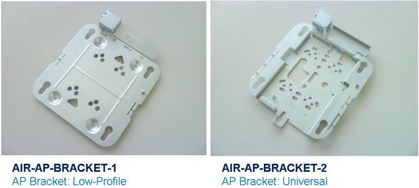
If the AP will be mounted directly to a ceiling on the gridwork, then AIR-AP-BRACKET-1 mounts flush and has the lowest profile. However, if the AP will be mounted to an electrical box or other wiring fixture, or inside a NEMA enclosure or perhaps wall mounted, then AIR-AP-BRACKET-2 is a better choice. The extra space in the bracket allows for wiring, and the extra holes line up with many popular electrical boxes. When mounting the bracket to the ceiling gridwork, some ceiling tiles are recessed. For this reason, two different styles of ceiling clips, recessed and flush rails, are available (Figure 17).
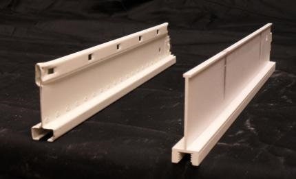
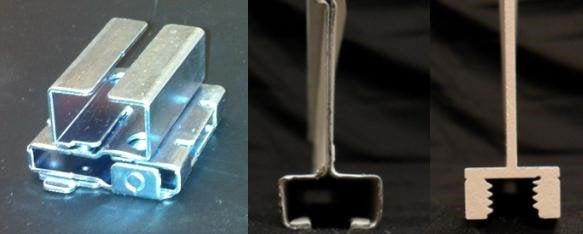
Channel Rail Adapters-Cisco Part Number AIR-CHNL-ADAPTER
When mounting APs to ceiling channel rails such as the ones shown in Figure 18, an optional channel adapter is used: AIR-CHNL-ADAPTER. It comes in a two-pack and attaches to the ceiling grid clip above. Refer to Figures 18 and 19.
PoE (Power over Ethernet) IEEE Standards
The following is a short list of IEEE standards and what they mean.
802.3af (circa 2003) allows for PoE up to 15.4W
802.3at (circa 2009) allows for PoE up to 30W sometimes called PoE+
802.3bt (circa 2017) allows for PoE up to 60W sometimes called PoE++
Note |
UPoE (circa 2010) Cisco proprietary method, allows up to 60W. 802.3bt (circa Sept 2018) allows for PoE up to 90W. Sometimes called 4PPoE as it injects power on 4 pairs. |
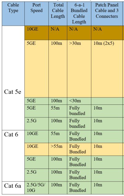
Multigigabit Ethernet (mGig)
802.3bz (circa 2015) also referred to as NBASE-T and mGig. This is about going faster than GbE (Gigabit Ethernet) using standard CAT-5 and CAT-6 cabling systems. The below chart lists the various types of Ethernet cable and the distances supported. Note there is also a feature known as downshift, if the cable experiences too much crosstalk in a bundled cable, it can shift down from 5GE to 2.5G or even 1G.
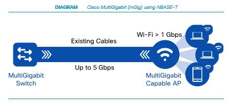
Cisco mGig switches are capable of 60W using Cisco Universal Power over Ethernet (UPoE)
The 60W PoE and faster mGig throughput are ideal for devices such as the AP-3800 with module support, allowing plenty of power and throughput for 3rd party after market modules that can be installed in the AP. For more on this see the AP-3800 deployment guide in the appendix URL #3
Additionally, more powerful Access Points such as the AP-4800 with Hyperlocation and future 802.3ax standards based Access Points can also take advantage of Cisco UPoE and mGig throughput enhancements.
For more on mGig and mGig capable switches see the appendix URL #6
Access Point Powering Options
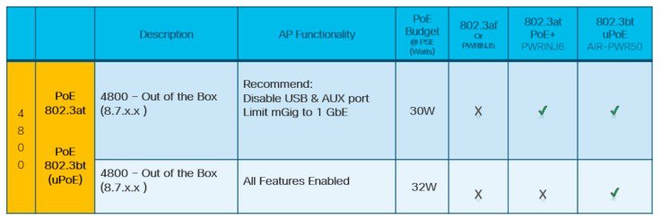
The AP-4800 supports a local DC power supply Cisco Part Number AIR-PWR-50 and will draw 28.7W
When using a Power over Ethernet (PoE) source, for best performance an 802.3bt / universal (uPoE) source is best. Any switch supporting Multigigbit (mGig) should be able to supply uPoE over 32W.
The AP-4800 will not function using older 802.3af (15.4W) PoE systems, but will function in a slightly reduced mode (USB power off and limiting the aux port and reducing mGig to GbE rates. This is a very powerful Access Point, we are looking to optimize all features at 30W in a later release, however that has not been committed as of 8.7.
While the AP-4800 will work fine with CAT-5e, Cisco recommends that customers use CAT6a for new installations, as this is the cabling required by the 10GE standard.
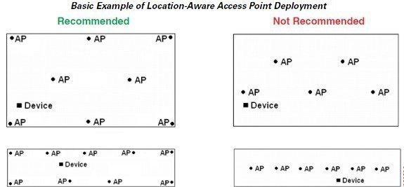
General Design Guidelines Access Point Spacing Recommendations
If you have a Wi-Fi device such as an AP and you are going to use another AP in the vicinity on a different channel, it is recommended that you space each AP apart by approximately 6 Ft (2 meters). Avoid clustering the APs or the antennas from different APs together, as this could cause degradation in performance. This recommended distance is based on the assumption that both devices operate in the unlicensed band and do not transmit RF energy more than 23 dB - that is, 200 mW. If higher power is used, space farther apart.
Should you have other devices that transmit, especially if they operate in the same frequency ranges, for example, frequency hopping legacy APs or other devices that operate close in frequency to those of the AP (think below or above the 2.4 and 5 GHz band), you should consider moving or separating the devices as far apart as can reasonably be done. After you have done this, check for interference by testing both devices at the same time under heavy utilization (load) and then characterize each system independently to see how much, if any, degradation exists.
 Warning |
In order to comply with FCC, EU, and EFTA RF exposure limits, antennas should be located at a minimum of 7.9 inches (20 cm) or more from the body of all persons. See the installation guide under declaration of conformity for more on this. |
Installations in IDF Closets (Telecommunications or other Electrical Equipment)
When installing APs near other electrical or telecommunications equipment, keep all wiring and metal away from the antennas and avoid placing the antennas near electrical lines. Do not route wiring electrical or Ethernet in the near field (6-15 inches) from the antenna. Try to refrain from installing the AP in the electrical closet, as the best place for the AP is as close to the users as possible/practical. If you remote antenna cables from such a closet, you may be required to use Plenum rated cable (see local fire/safety regulations for more on this).
Installations at Very High Altitudes
While not defined in the specification sheet for the AP-4800, and the customer should determine their own suitability with regard to this, Generally speaking most Cisco-Aironet Access Points have passed functional checks after a Non-Operational altitude test of 25C @ 15,000 Ft was performed. Additionally, they passed a functional test during an operational altitude test of 40C @ 9,843 Ft.
All units in the test group were connected to at least one WLAN client and monitored for continual operation passing traffic, and performing constant ping testing throughout the operational altitude test.
Mixing Access Points of different models and types
The AP-4800 is a very advanced Access Point integrating features such as Cisco’s Intelligent Capture for instant network analysis. Intelligent Capture probes the network and provides DNA Center with packet inspection, capture and full analysis. The software can track over 240 anomalies and instantaneously review all packets on demand, emulating the onsite network administrator. Intelligent Capture allows for more informed decisions on your wireless networks.
However; Intelligent Capture relies on analytics provided by the highly advanced AP-4800 radio and other advanced radio hardware features such as Hyperlocation that are not typically found on other Cisco-Aironet Access Points.
For this reason it is not recommended that you mix Access Point models, sometimes called “salt and pepper” as it would diminish the performance of the DNA network, degrading many of our advanced features such as intelligent capture.
For this reason, if you have a mixture of AP types, it is recommended that you group like access points together for example AP-3800’s on say one floor and AP-4800’s on another and refrain from mixing them.
For more on Cisco’s Digital Network Architecture (DNA) with Intelligent Capture see the appendix URL #7
Stadium / Harsh Environments
Customers wishing to install the AP in harsh environments exposed to weather, such as sporting areas, stadiums, open garden areas or warehouse freezers, may wish to use a NEMA type enclosure.
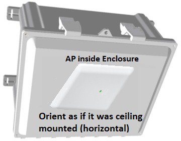
When using a NEMA type enclosure, try to have the cables exit out of the bottom of the enclosure so that rain and moisture do not run down the cable into the enclosure. Note: the color of the enclosure may affect the heat rating; for example, a black enclosure gets much hotter in the sun then a white one.
You may also want to use a pressure vent to prevent moisture accumulation.
Warehouse and Factory
Warehouse installations are often difficult because of the very high ceilings and the clutter of the material being warehoused. When performing a coverage check (site survey) always check the coverage at “full stock” levels as the material being warehoused can change the RF coverage creating loss of uniform coverage creating “dead spots”
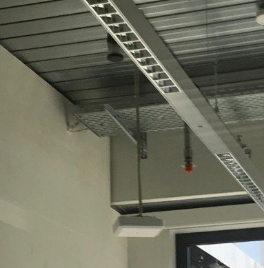
When practical position the APs as close to the users as possible ideally suspending the AP-4800 12-15 feet (enterprise ceiling height) when practical to do so. See section above on electrical box mounting for pictures.
If the AP is 30 feet in the air, (that is an additional 30 feet farther the signal has to go, “best case”). When configuring coverage for aisles, try to use directional (Patch) antennas on the wall and shoot down the aisles; or use low-gain Omni-directional antennas on the ceiling (such as dipoles) or units with integrated antennas as high gain omnidirectional antennas tend to have more nulls.
Note |
The AP-4800 is similar to the AP-3800i in WLAN cell size and performance; however, the AP-3800e Access Point supports external antennas and may be a better choice when directional cells are required. |
Installations Inside and Around Elevators
Elevator coverage can sometimes be accomplished by placing APs in the near field of the elevator, typically on each floor near the elevator door. Since elevators often have metal doors and the shafts are often concrete or contain other materials that degrade Wi-Fi coverage, it is important to check the coverage inside the elevator. While such coverage can be challenging it is often do-able, especially if the elevator is only a few floors.
High-rise elevators are more challenging since roaming issues are problematic as the client is cycling through a large number of APs rather quickly. Some companies that do in-elevator advertising have put a patch antenna on the floor inside the shaft and a patch antenna (or the actual AP) on the bottom of the elevator car, while other companies have used leaky coaxial cable running on the side of the shaft.
When installing any Wi-Fi equipment inside the elevator cars or shafts, local regulations need to be followed as many times such installations are prohibited either for safety reasons or because the building owner or local fire department may prohibit same. Also, it is dangerous and only elevator repair persons or contractors experienced with this kind of work should be in those areas. When the need for external antennas is a requirement, again position/use the AP-3800e
AP-4800 General Guidelines
Following are some guidelines to remember regarding Access Point installations.
-
Always try to mount the AP as close to the users as possible for best performance. Be aware of the environment; for example, hospitals have metal doors, coverage can change when the doors close, old buildings can have metal grid work in the plaster or asbestos. Avoid mounting the AP or antennas near metal objects, as doing so can change the coverage area affecting clients as well as Hyperlocation accuracy.
-
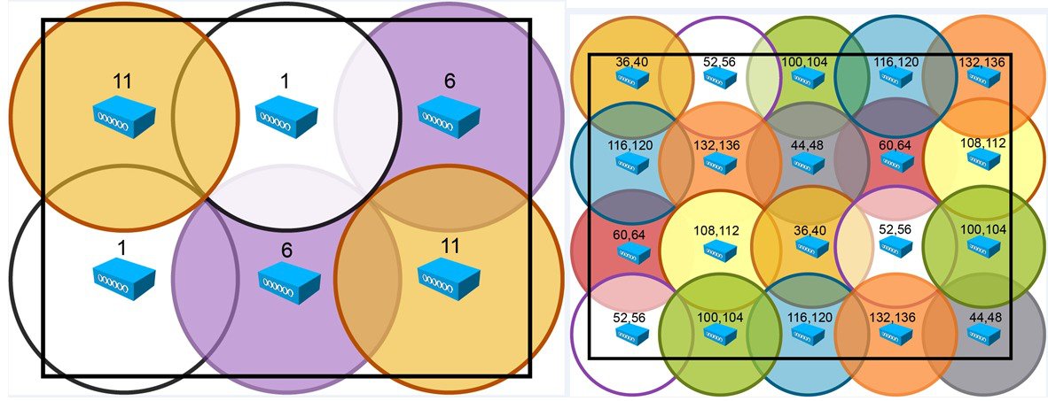
When using the 2.4 GHz frequency, the same 1, 6 and 11 channel scheme is used as is the 5 GHz channel scheme. Avoid putting all of the APs on the same channel, and reuse channels as you can.
-
Cisco RRM, FRA and other features can help automate the process.
Figure 28. Typical Wi-Fi spacing, however the AP-4800 has Hyperlocation (see figure 5 above) s
-
4. Try to determine which clients are heavily used checking the coverage with those clients. For example, a PDA or Wi-Fi phone might not have the same range as a notebook or tablet.

Tip
Verify coverage using the worst performing clients that you intend to deploy.
-
While site surveys are highly recommended, if the design is done at half power and Cisco RRM is in place, sometimes a limited site survey (coverage check) is adequate for smaller venues. If this is a very challenging environment such as train connectivity, Gas & Oil verticals, large hospitals, etc., Cisco has an Advanced Services team that can be contracted to help you get up to speed or perform your installation. See your Cisco account team for more information.
Access Point antenna placement
AP-4800 Access Point has an advanced antenna system but correct placement of the AP is critical.
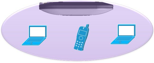
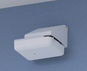
If the AP is not mounted on the ceiling but rather on a wall, this may acceptable for smaller deployments such as hotspots, kiosks, transportation or smaller coverage areas but in an enterprise deployment it could cause excessive roams as the signal. Looking at the diagram above and then picture turning on its side In this orientation the signal can radiate on the floor above and below rather than downward in a uniform 360 pattern. Result is a non-uniform cell size often resulting in excessive roaming resulting in poor WLAN phone performance.
4800 Series Antenna System Overview and Patterns
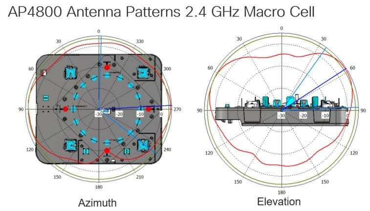
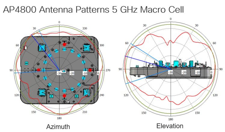
The AP-4800 has the most advanced antenna system Cisco has put on an AP to date and contains:
-
Four Dual Radiating Element (DRE) 2.4/5GHz Macro cell antennas
-
Four Single Radiating Element (SRE) 5 GHz Micro cell elements
-
One Bluetooth Low Energy antenna element for BLE Beacon support
-
Sixteen Element active Hyperlocation antenna array, unlike the previous Hyperlocation array that was part of the 2600/3700 module upgrade, this antenna array is digitally switched thus providing four Omni-directional elements dynamically from the array for packet sniffing, Analytics and DNA assurance.
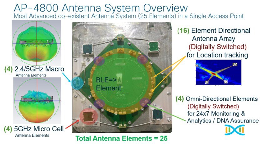
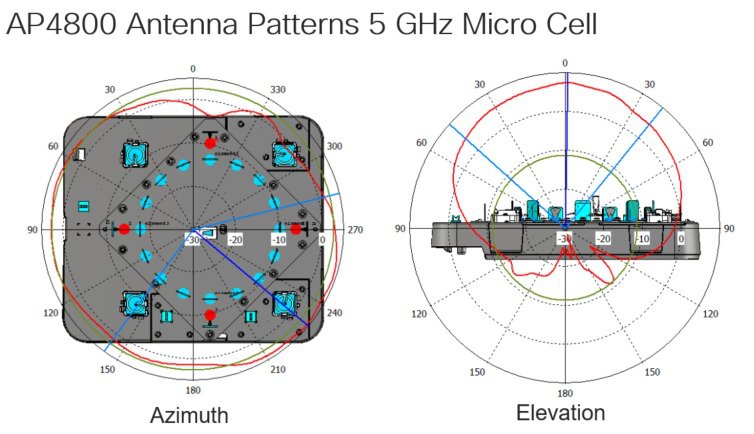
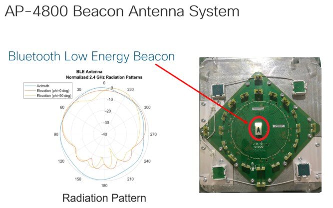
Note |
The AP-4800 uses this antenna for all beacon transmissions, the AP is able to support up to five different beacons however; it uses the Hyperlocation array and the Cisco CleanAir chipset to decode beacons (receive). This allows for future enhancements such as beacon tracking etc. For an overview on BLE see the appendix URL # |
Appendix
Useful URLs within the guide:
-
Cisco CleanAir Whitepaper https://www.cisco.com/c/en/us/solutions/collateral/enterprise-networks/cleanair-technology/white_paper_c11-599260.html
-
Flexible Radio Assignment and Dual 5 GHz Operation https://www.cisco.com/c/en/us/td/docs/wireless/controller/technotes/8-3/b_RRM_White_Paper/b_RRM_White_Paper_chapter_01000.html
-
Flexible Radio Cisco Aironet 2800/3800 Deployment guide https://www.cisco.com/c/en/us/td/docs/wireless/controller/technotes/8-3/b_cisco_aironet_series_2800_3800_access_point_deployment_guide.pdf
-
Overview of Hyperlocation https://www.cisco.com/c/en/us/solutions/enterprise-networks/hyperlocation-solution/index.html
-
Hyperlocation Deployment Guide https://www.cisco.com/c/en/us/td/docs/wireless/controller/technotes/8-2/b_hyperLocation_best_practices_and_troubleshooting_guide.html
-
Cisco Mulitigigabit mGig overview along with supported switches https://www.cisco.com/c/en/us/solutions/enterprise-networks/catalyst-multigigabit-switching/index.html
-
Cisco’s DNA architecture overview https://www.cisco.com/c/dam/en/us/solutions/collateral/enterprise-networks/cisco-digital-network-architecture/solution-overview-c22-736580.pdf
 Feedback