Access point power save
Access point power save is a power management capability that
-
enables APs to reduce energy consumption during periods of inactivity
-
supports flexible scheduling and policies for low-power operation, and
-
helps optimize network efficiency without compromising performance.
This feature is critical in modern enterprise environments where reducing operational costs and improving environmental impact are priorities. Cisco APs offer multiple configurations to enable power save modes, such as calendar-based scheduling and client threshold triggers
Feature history for access point power save
|
Release |
Feature Information |
|---|---|
|
Cisco IOS XE Cupertino 17.8.1 |
This feature allows a network administrator to force APs to operate in low-power mode to reduce power consumption. |
For more information about the APs that support the AP Power Save feature, see https://www.cisco.com/c/en/us/td/docs/wireless/access_point/feature-matrix/ap-feature-matrix.html.
Tips for AP power save configuration
-
Use calendar profiles for predictable power reduction: You can define regular sleep intervals using calendar profiles to maximize energy savings without disrupting business hours.
Requirements for AP power save configuration
-
Enable RLAN port before using PoE-out: PoE-out functionality requires the RLAN port to be enabled. Ensure this is configured before applying any PoE-out power profile.
Best practice for AP power save configuration
-
Setting client thresholds: Set the client wakeup threshold to a realistic minimum (e.g. 3–5 clients) to avoid unnecessary power cycling and improve user experience.
Warnings for AP power save configuration
-
Do not disable uplink interfaces: Do not configure the AP uplink Ethernet port for shutdown in any power profile. The uplink is required for controller communication and management
AP power policies
Access point power policies are a set of policies that
-
define power budget utilization for an AP
-
allow management of different interfaces on an AP, and
-
support different modes for Cisco Catalyst 9124 APs under insufficient power conditions.
These policies help adapt AP behavior to different input power scenarios (for example, 802.3af, 802.3at, 802.3bt, DC) and ensure reliable operation even under limited power supply.
Use case for AP power policy
These are the use cases of an AP power policy:
-
Define a power policy for available power inputs, such as 802.3af, 802.3at, 802.3bt, and DC power.
-
Predetermine AP operations for non-802.3bt power situations with tri-radio or quad-radio APs.
Power-save modes
A power-save mode is a wireless AP power management feature that
-
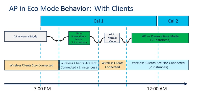
enables the AP to switch to a low-power state when no clients are associated
-
reduces energy consumption by minimizing AP activity during off-peak hours, and
-
allows organizations to improve energy efficiency and support environmentally conscious initiatives.
Additional reference information
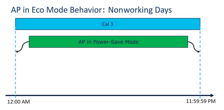
When power-save mode is enabled, the AP can "fall asleep" after hours in workspaces or other deployment scenarios where client activity is absent, thereby saving power throughout the night.
These are the advantages of power save mode:
-
Increases the energy saving per AP: By reducing AP functions during off-peak hours, power-save mode can save an additional 20 percent in energy costs compared to the regular idle mode.
-
Enables environmentally conscious purchases: Large enterprises and companies often track environmental performance as a key index. Power-save mode helps support these goals by enabling centralized monitoring of energy efficiency by energy teams.
Use case for power save mode
During after hours in a workspace, when no wireless clients are connected, the AP enters power-save mode and reduces its power usage automatically for the duration of the night.
Release-specific feature support
PoE profiles
A PoE profile is a power allocation framework that
-
facilitates negotiation and adaptation of power levels based on AP requirements
-
comprises fixed and flexible options for interface configuration, and
-
supports policy-based profiles customized for both normal and power-saving operational modes.
Types of PoE profiles
-
Fixed PoE profiles: predefined settings per model, typically for full-power mode.
-
Fixed PoE Profiles enable APs to negotiate the power required from the switches they are connected to. The power needed can vary between different AP models.
-
If an AP does not receive the power it requests, it operates within the power budget. It can cause certain interfaces to function under degraded conditions. For instance, radios might operate at 2SS instead of their full 4SS capability.
-
These profiles are used when APs are in normal operation mode (nonpower-save mode). During power-save mode, the configured PoE power policies are applied instead.
-
-
PoE Power Policy: schedule-based profiles for different times of day.
-
PoE Power Policies allow for the configuration of interfaces to specific speeds or settings according to a schedule.
-
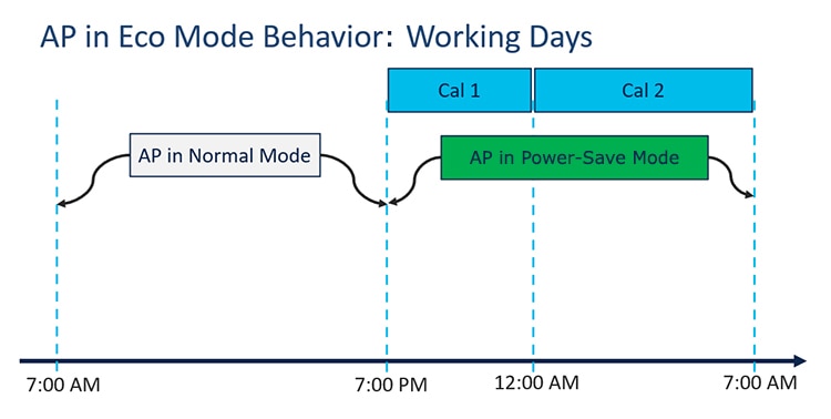
These policies can push a defined profile to APs based on timing or calendar settings, such as turning off all but the 2.4-GHz radio and the multigigabit Ethernet at 100 MB at specific times, for example, from 7 p.m. to 7 a.m. on a group of APs located on a second floor.
-
-
Flexible PoE Profiles: customizable profiles for interface-level power control.
-
Flexible PoE Profiles allow you to configure different interfaces with specific parameter values and states, instead of fixed profile rules.
-
In case an AP does not obtain the necessary power, it operates under the power budget, following the guidelines of the flexible PoE profile.
-
Additional Reference Information
-
Operational parameters for each AP interface may be modified based on the hardware specifications, as detailed in the accompanying tables.
AP power draw specifications
This section provides detailed specifications on the power draw requirements for various AP models to enable accurate planning and deployment in network setups.
|
AP |
Power Draw Specification |
|---|---|
|
Cisco Wireless 9172 Series Access Points |
See the Input power requirements in the Product specifications section of Cisco Wireless 9172 Series Access Points Data Sheet |
|
Cisco Wireless 9176 Series Access Points |
See the Input power requirements in the Product specifications section of Cisco Wireless 9176 Series Access Points Data Sheet |
|
Cisco Wireless 9178 Series Access Points |
See the Input power requirements in the Power over Ethernet section of Cisco Wireless 9178 Series Access Points Data Sheet |
|
Access Points |
PoE-In-Mode/DC Mode |
Consumption @ Power Device |
Consumption @ Power Source Equipment |
Feature Mode |
||||||
|---|---|---|---|---|---|---|---|---|---|---|
|
AP |
Worst-Case Cable |
Radio 1 |
Radio 2 |
Radio 3 |
Ethernet |
USB |
Module |
PoE-Out |
||
|
Cisco Catalyst 9115AXI Access Points |
.3af |
13.0 |
15.4 |
2X2 |
2X2 |
— |
1G |
N |
— |
— |
|
.3at |
16.0 |
18.9 |
4X4 |
4X4 |
— |
2.5G |
N |
— |
— |
|
|
.3at |
20.4 |
24.1 |
4X4 |
4X4 |
— |
2.5G |
Y(3.75W) |
— |
— |
|
|
Cisco Catalyst 9115AXE Access Points |
.3af |
13.0 |
15.4 |
2X2 |
2X2 |
— |
1G |
N |
— |
— |
|
.3at |
17.0 |
20.1 |
4X4 |
4X4 |
— |
2.5G |
N |
— |
— |
|
|
.3at |
21.4 |
25.3 |
4X4 |
4X4 |
— |
2.5G |
Y(3.75W) |
— |
— |
|
|
Cisco Catalyst 9117 Access Points |
.3af |
13.5 |
15.4 |
2X2 |
2X2 |
— |
2.5G |
N |
— |
— |
|
.3at |
25.0 |
29.3 |
4X4 |
8X8 |
— |
5G |
N |
— |
— |
|
|
.3at |
24.1 |
28.0 |
4X4 |
4X4 |
— |
5G |
Y(4.5W) |
— |
— |
|
|
.3bt/UPoE |
30.0 |
32.7 |
4X4 |
8X8 |
— |
5G |
Y(4.5W) |
— |
— |
|
|
.3at/.3bt/UPoE |
22.4 |
25.7/23.8/23.8 |
4X4 |
4X4 |
— |
2.5G |
Y(4.5W) |
— |
— |
|
|
Cisco Catalyst 9120AXI/E Access Points |
.3af |
13.8 |
15.4 |
1X1 |
1X1 |
Enabled |
1G |
N |
— |
— |
|
.3at |
20.5 |
23.2 |
4X4 |
4X4 |
Enabled |
2.5G |
N |
— |
— |
|
|
.3at |
25.5 |
30.0 |
4X4 |
4X4 |
Enabled |
2.5G |
Y(4.5W) |
— |
— |
|
|
Cisco Catalyst 9130AXI/E Access Points |
.3af |
13.8 |
15.4 |
1X1 |
1X1 |
Enabled |
1G |
N |
— |
— |
|
.3at |
25.5 |
30.0 |
8X8 |
4X4 |
Enabled |
5G |
N |
— |
— |
|
|
.3at |
25.5 |
30.0 |
Primary 4X4 Secondary Off |
4X4 |
Enabled |
5G |
Y(4.5W) |
— |
— |
|
|
.3at |
25.5 |
30.0 |
Primary 4X4 Secondary 4X4 |
Disabled |
Enabled |
5G |
Y(4.5W) |
— |
— |
|
|
.3bt |
30.5 |
33.3 |
8X8 |
4X4 |
Enabled |
5G |
Y(4.5W) |
— |
— |
|
|
Access Points |
PoE-In-Mode |
Consumption @Power Device |
Consumption @Power Source Equipment |
Feature Mode |
||||||||
|---|---|---|---|---|---|---|---|---|---|---|---|---|
|
at AP |
Worst-Case Cable |
5G Radio |
2G Radio |
6G Radio |
AUX Radio |
Mgig0 |
Mgig1 |
USB |
Module |
PoE-Out |
||
|
Cisco Catalyst 9136 Series Access Points |
.3af - Fixed |
13.9 |
15.4 |
Disabled |
Disabled |
Disabled |
Enabled |
1G |
Disabled |
Disabled |
— |
— |
|
.3at - Fixed |
24.0 |
27.90 |
Primary - 4X4 Secondary - Disabled |
2X2 |
2X2 |
Enabled |
2.5G |
2.5G (hitless failover standby) |
Disabled |
— |
— |
|
|
.3bt - Fixed |
43.4 |
54.81 |
8X8 or Dual 4X4 |
4X4 |
4X4 |
Enabled |
5G |
5G |
Y(9W) |
— |
— |
|
|
.3bt - PoE Policy 1 |
37.3 |
41.63 |
8X8 or Dual 4X4 |
4X4 |
4X4 |
Enabled |
5G |
5G |
Disabled |
— |
— |
|

 Feedback