- Cisco Mobility Express Overview
- Deploying Cisco Mobility Express
- Configuring Cisco Mobility Express controller
- Using internal DHCP server on Cisco Mobility Express
- TLS Support on Mobility Express
- Configuring Cisco Mobility Express for Site Survey
- Creating Wireless Networks
- Managing Services with Cisco Mobility Express
- Managing the Cisco Mobility Express Deployment
- Master AP Failover and Electing a new Master
TLS Support on
Mobility Express
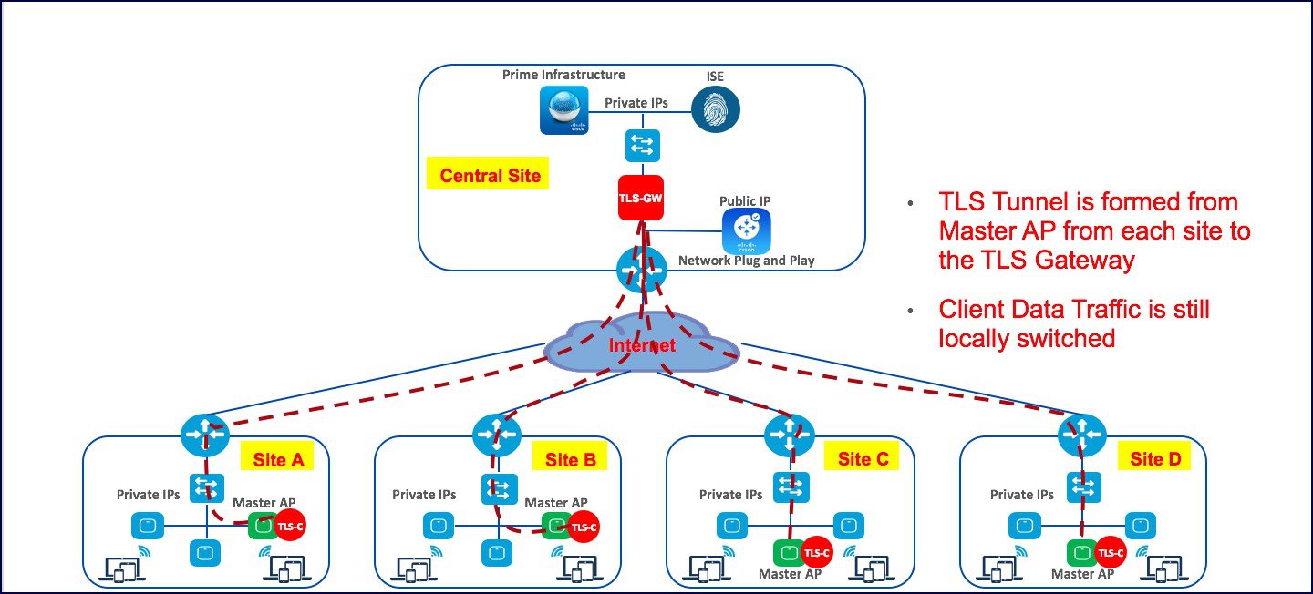
Cisco Mobility Express is a virtual wireless controller function embedded on 802.11ac Wave 2 Access points. With the flexibility of running a wireless LAN controller function on an access point, customers can deploy an Enterprise wireless solution on a single site or multiple sites with up to 100 Access Points at each site. In a multi-site deployment, customers can manage each of the sites using Cisco Prime Infrastructure which would typically be deployed in a central site. However, if the individual sites are connected to the internet via an ISP and are not connected via a dedicated WAN, managing these multi-site deployments can pose a challenge.
To overcome this challenge, starting AireOS Release 8.6, Cisco Mobility Express, customers can now manage the multi-site deployment using Cisco Prime Infrastructure over a TLS Tunnel. In addition to managing these sites, they can also aggregate their DOT1x authentication request to a RADIUS(ISE) which can be deployed along site CPI at the central site.
Please note that only SNMP, RADIUS and SSH traffic flows on the TLS tunnel to the central site and data traffic is still switched locally at individual sites.
TLS Tunnel has two components
- TLS Client–Starting AireOS Release 8.6, TLS Client has been embedded in the Cisco Mobility Express code and will run on the Master AP
-
TLS Gateway –This is a Virtual Machine which is deployed at the central site to establish the TLS Tunnel. TLS Gateway has two network interfaces
-
Public Network–This is the public IP which is reachable from every Master AP. The TLS client establishes a TLS tunnel between Master AP and TLS Gateway using this address.
-
Private Network–This the IP address of the private network behind the TLS Gateway where the Cisco Prime Infrastructure, RADIUS and other network devices are deployed.
-
TLS Gateway
TLS Gateway is virtual machine and is deployed at the central site.
System Requirement for TLS Gateway
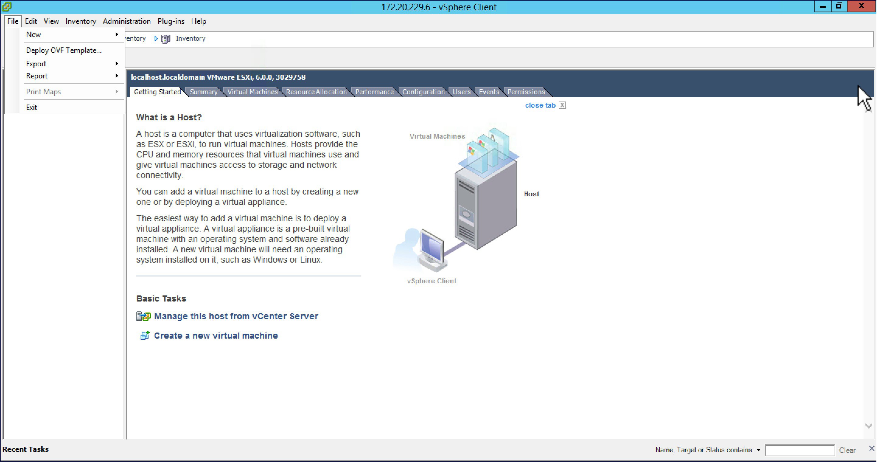
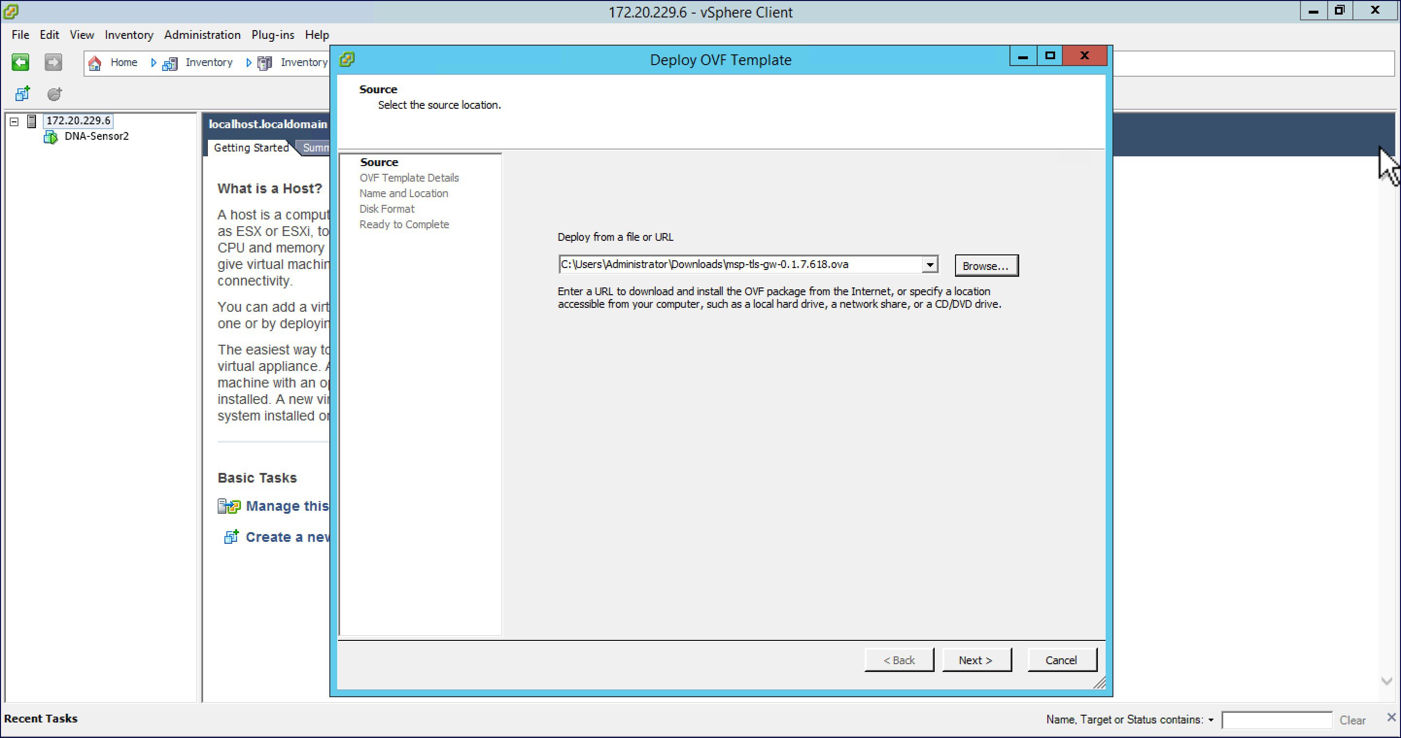
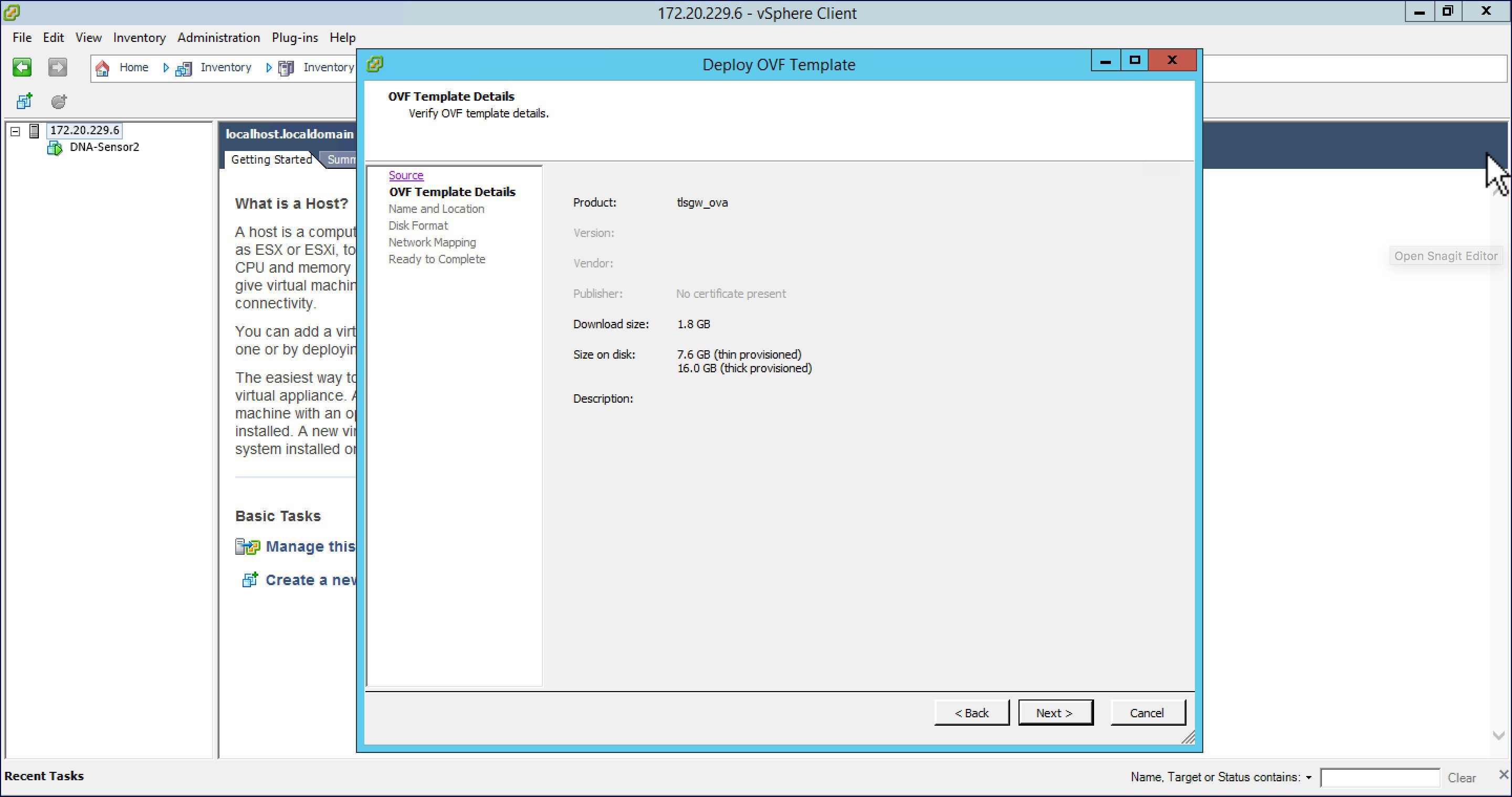
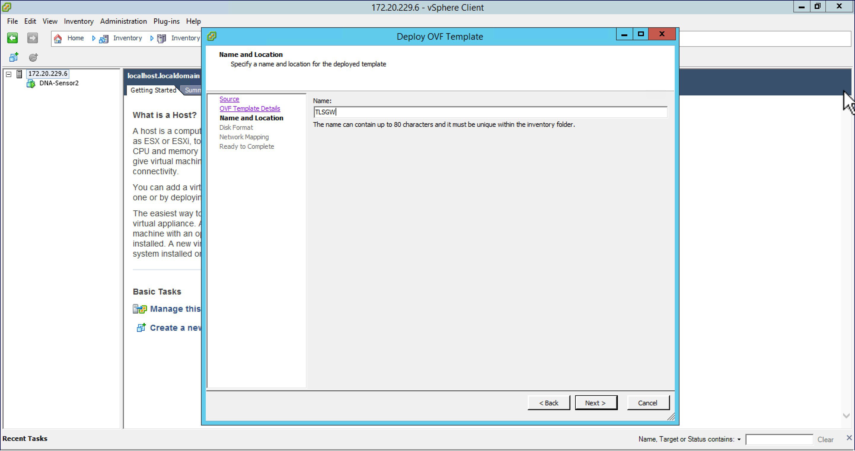
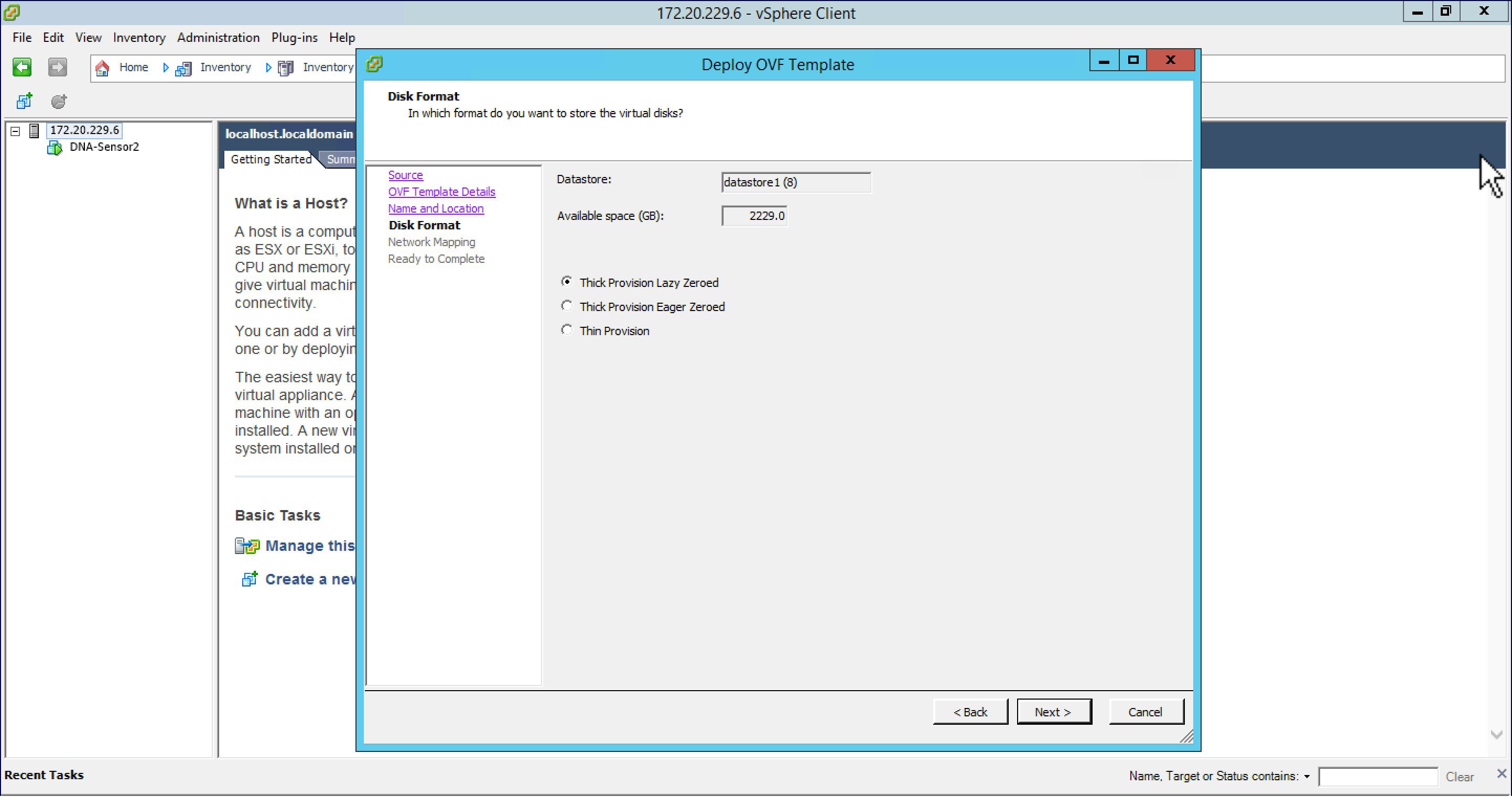
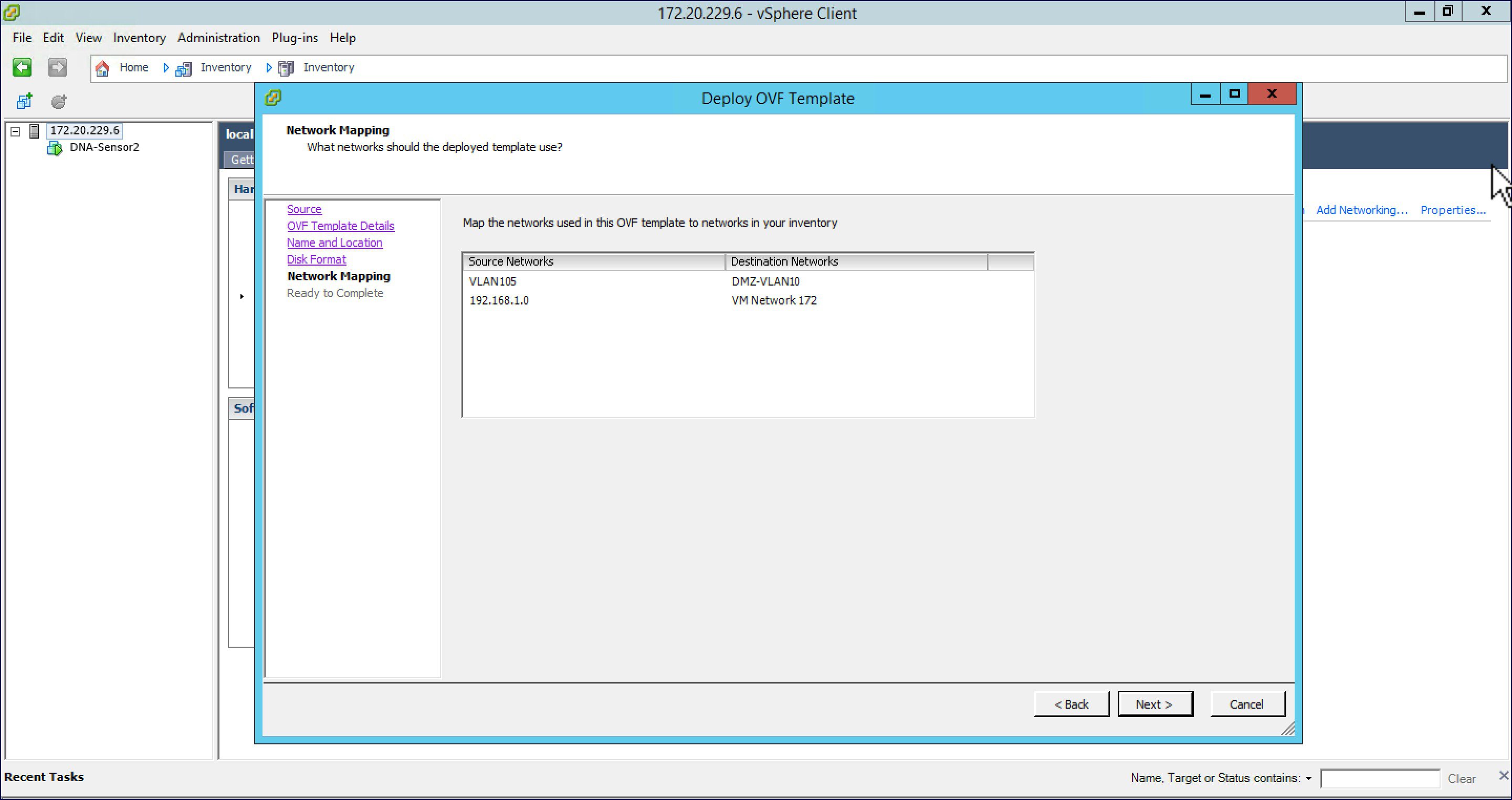
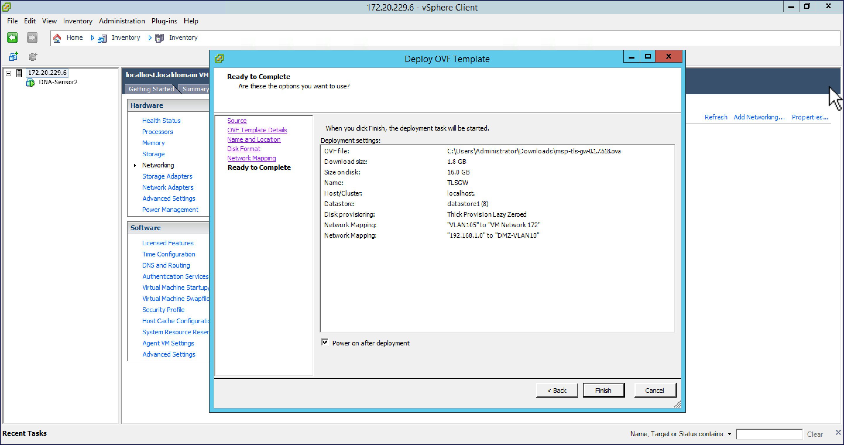
Deploying TLS Gateway
Please follow the steps below to deploy a TLS Gateway at the central site.
Configuring TLS Gateway
Configuring the TLS Gateway comprises of 3 things:
-
Configure the IP address for Public and Private network interfaces
-
Configure the TLS Gateway configuration file and start the service
-
Configuring the PSK ID-KEY Pair
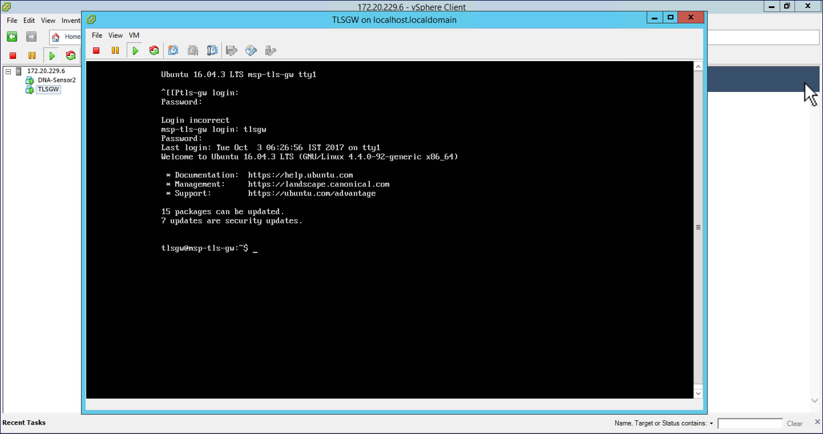
After the OVA for TLS Gateway is deployed and powered up, follow the steps below to configure the TLS Gateway.
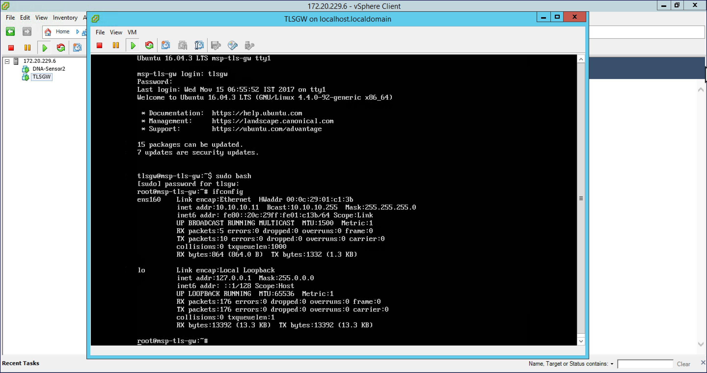
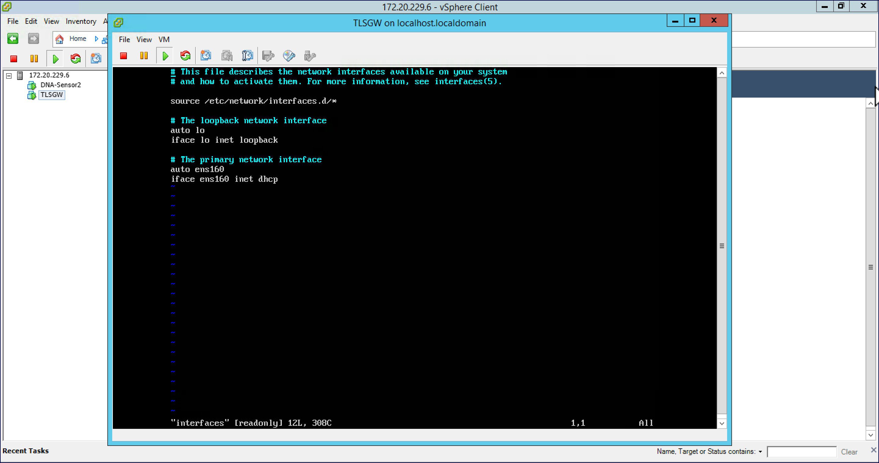
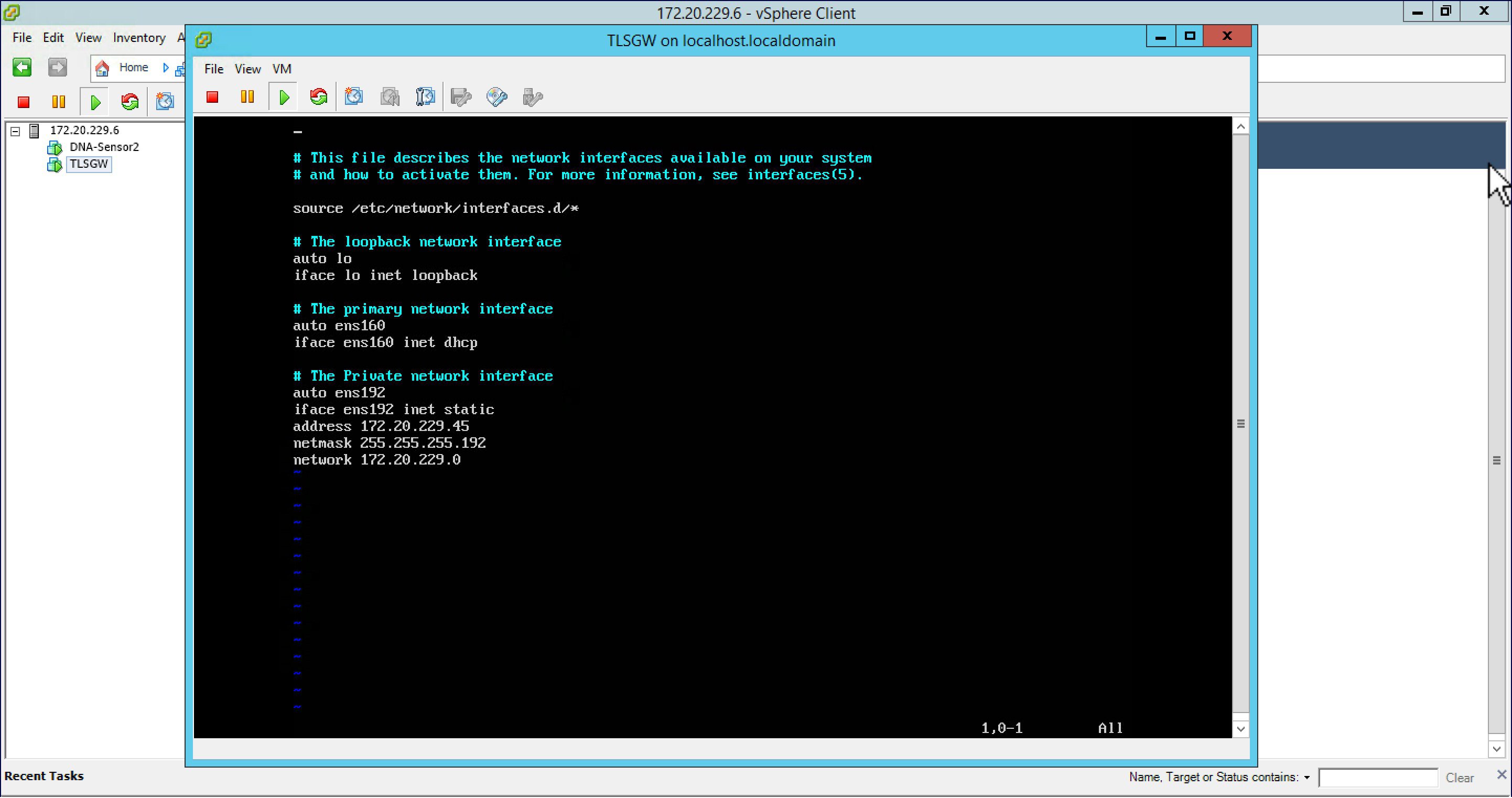
Configuring IP Address for Public and Private network interfaces
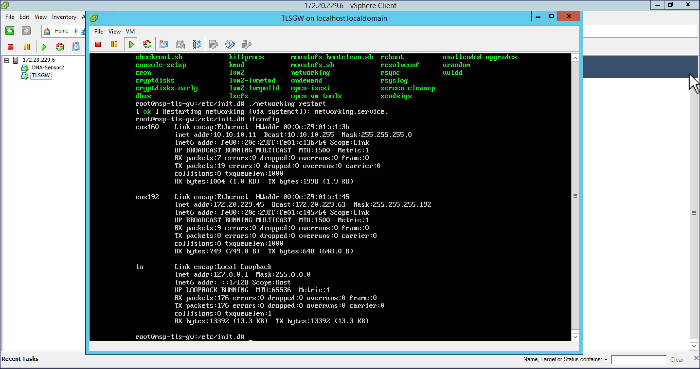
Configure the TLS Gateway configuration file and start the service
| Step 1 | : Go to
/opt/cisco/msp-tls-gw/bin/
and edit the
tlsgw_config.txt
with the following:
server_listening_ipv4_address=10.10.10.11 // Public IP of TLS Gateway
server_listening_port=443 // Port
server_private_ipv4_address=172.20.229.45 // Private IP of TLS Gateway
prefix_subnet=172.20.229.0 // Private IP network of TLS Gateway
prefix_length=26
debug_level=4 // Loglevel for TLS Gateway
dhcp_static_pool_ipv4=20.1.0.0:255.255.0.0 // Local IP pool configured for TLS Client IP allocation
dpd_interval=60 // Dead Pear Detection timer value for client
rekey_interval=3600 // Rekey timer value  for client
retry_interval=20 // Retry timer value for client
| ||
| Step 2 | Save the file. | ||
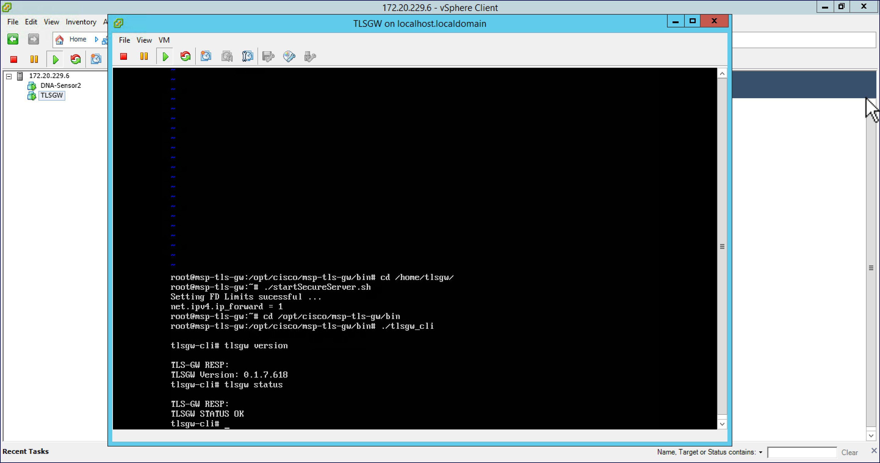
| Step 3 | Go to /home/tlsgw and start the TLS Gateway service with script ./startSecureServer.sh | ||
| Step 4 | To verify that the TLS Gateway service is running successfully,
go to
/opt/cisco/msp-tls-gw/bin/
and run ./tlsgw_cli
as shown below.
|
Configuring the PSK ID-KEY pair
Configure the Pre Shared Key(PSK) on the TLS Gateway. This will be used by the TLS client on the Master AP to authenticate with the TLS Gateway.
 Note | A maximum of 3 PSK ID-KEY pairs can be set for TLSGW. PSK-ID can be any character string of length (3-50), PSK password(or key) can be any character string of length (5-256) , Character ':' or 'space' or 'tab' are not allowed for both psk-id and psk-key. |
To configure, follow the steps below:
| Step 1 | : Go to /opt/cisco/msp-tls-gw/bin/ and run ./tlsgw_cli |
| Step 2 | Configure the PSK using the following CLI:
tlsgw-cli# set-psk=cisco
 Setting PSK ID-KEY pair
Enter the PSK key for this ID:
TLS-GW RESP:
OK
|
| Step 3 | Verify that the PSK ID is configured using the following CLI:
tlsgw-cli# get all psk-id TLS-GW RESP: List of stored psk-ids: cisco 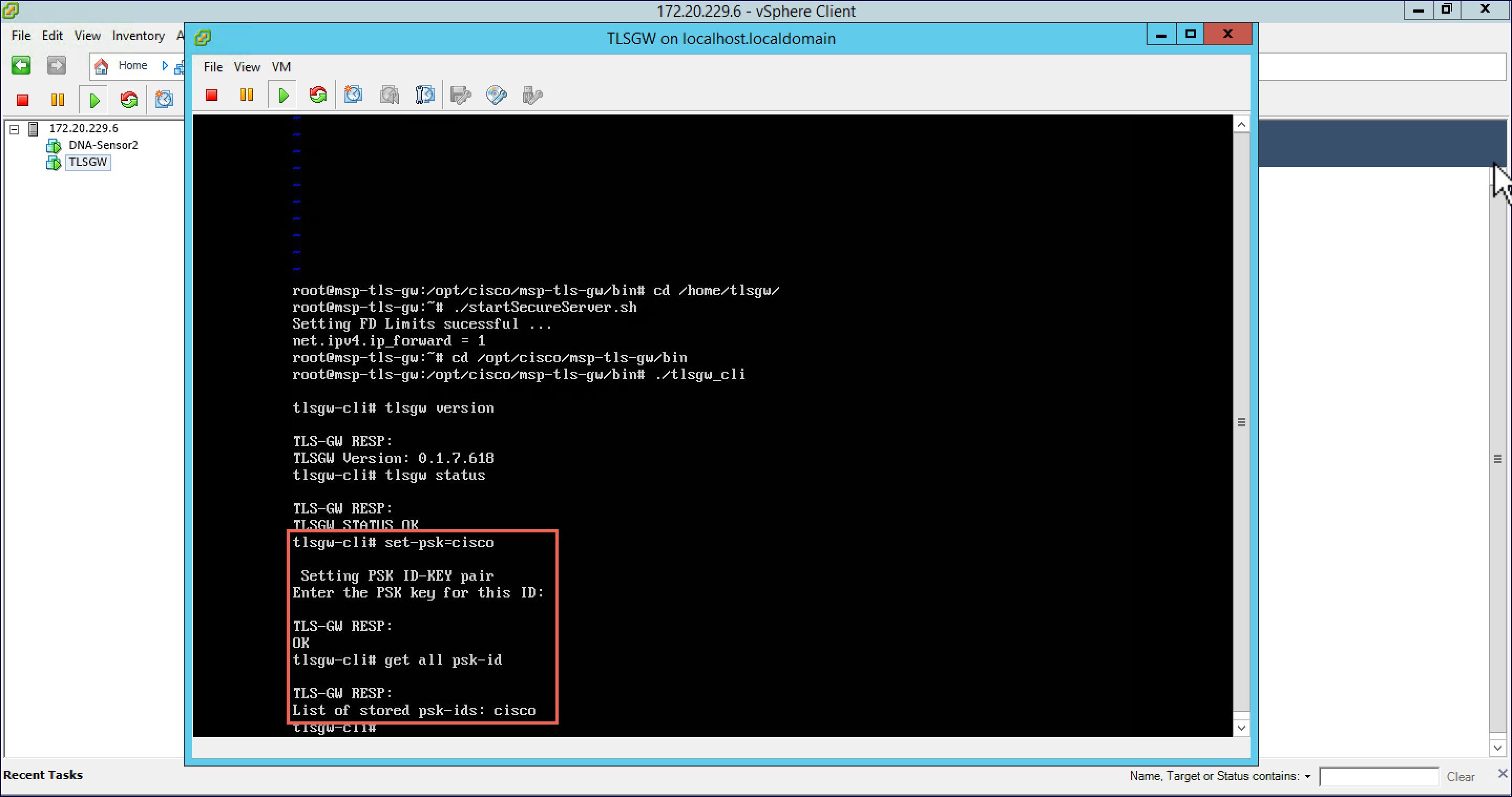
|
TLS Client
TLS Client is integrated in the AireOS Release 8.6 and is natively present in the code. For TLS client to establish a TLS tunnel with TLS Gateway, Master AP should be able to communicate with the Public IP of the TLS Gateway.
Pre-Requisites for TLS Client
-
Cisco Mobility Express AireOS release 8.6 or higher
-
TLS Gateway Public IP address should be reachable from the Master AP. If TLS Gateway FQDN is used then, TLS_GW FQDN should be configured in the local DNS server, and same DNS server IP should be configuring on ME controller to Resolve the FQDN of TLS Gateway
Configuring TLS Tunnel
There are two ways to configure the TLS Tunnel between TLS Client and TLS Gateway. They are as follows:
Option 1: Zero touch provisioning using Network PnP
During Day 0, one can download the controller configuration from Network PnP. The TLS Tunnel configuration can also be included in the controller configuration file such that after the Master AP downloads the configuration file, reboots, and comes back up, it will automatically establish a TLS Tunnel with the TLS Gateway.
Option 2: Manually configure the TLS Tunnel from WebUI
To configure the TLS Tunnel from the ME WebUI, follow the steps below:
| Step 1 | Switch to Expert View on the Controller WebUI | ||
| Step 2 | Navigate to Services > TLS from the menu on the left | ||
| Step 3 | On the TLS
Tunnel page, configure the following parameters:
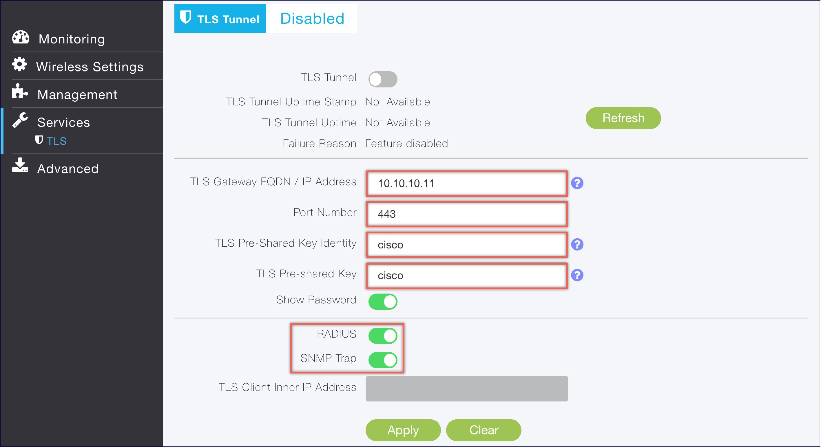
| ||
| Step 4 | Click Apply. | ||
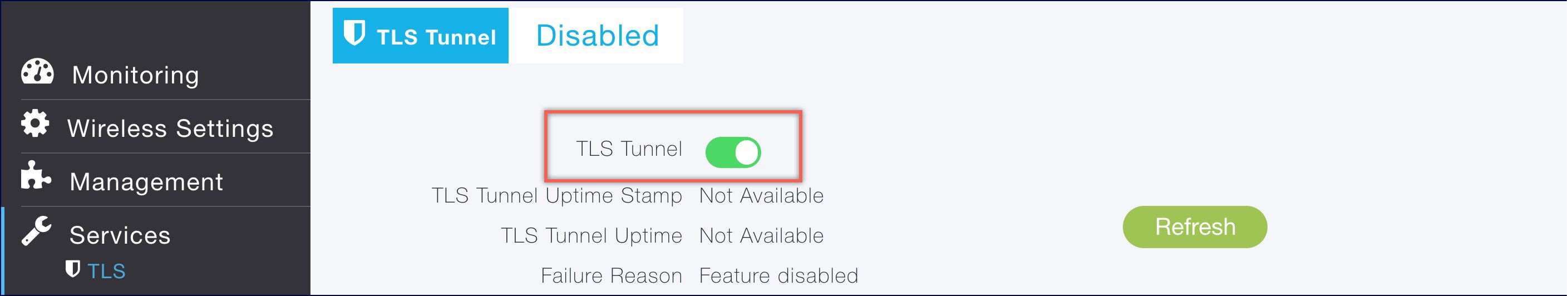
| Step 5 | Finally,
enable the TLS Tunnel at the top of the page. If all pre-requisites are met, a
tunnel would be created from the Master AP to the Public interface if TLS
Gateway.
 |
 Feedback