- Network Modules
- Mounting the Cisco ASR 901 10G Router
- Rack-Mounting Configuration Guidelines
- Mounting the Cisco ASR 901 10G Router in a Rack
- Wall-Mounting
- Connecting the Chassis Ground and Power
- Grounding the Cisco ASR 901 10G Router
- Power Connection Compliance
- Wiring the DC-Input Power Source
- Installing the DC Power Cord Retainer
- Installing the AC Power Cord Retainer
- Installing and Removing SFP Modules
- Connecting Cables
- Powering on the Router
Installing the Cisco ASR 901 10G Router
This chapter describes how to install the Cisco ASR 901 10G router, and how to connect it to external devices. These are the following sections:
- Network Modules
- Mounting the Cisco ASR 901 10G Router
- Connecting the Chassis Ground and Power
- Installing and Removing SFP Modules
- Connecting Cables
- Powering on the Router

Warning Only trained and qualified personnel should be allowed to install, replace, or service this equipment. Statement 1030
Warning This unit is intended for installation in restricted access areas. A restricted access area can be accessed only through the use of a special tool, lock and key, or other means of security.
Statement 1017
Network Modules
You can order the Cisco ASR 901 10G router with the following interface modules.

Note Interface modules are installed and shipped with the router; they are not field replaceable.
Mounting the Cisco ASR 901 10G Router
Note The Cisco ASR 901 10G router is qualified only for horizontal orientation. You should use additional safety measures for vertical orientation.
Each Cisco ASR 901 10G router includes rack-mounting brackets. Using the rack-mounting brackets, you can mount the Cisco ASR 901 10G router in a 19-inch, 23-inch, or an ETSI rack that conforms to the EIA-310-D specification.
Using the two rack-mounting brackets for mounting, you can recess Cisco ASR 901 10G router in the equipment rack. This arrangement provides extra space in front of the router for the cables and allows you to close the doors of racks equipped with front-close doors.
To attach or replace the rack-mounting brackets, see the “Attaching Brackets to the Router” section.
The rack-mounting brackets are slotted to allow the router to be mounted in racks with EIA 1.25-inch (3.175-cm) or WECO 1.0-inch (2.54-cm) hole spacing. When installed in the rack, the Cisco ASR 901 10G router requires one EIA 1.75-inch (4.4-cm) vertical mounting space (or 1 rack unit [RU]) for mounting (see the “Mounting the Cisco ASR 901 10G Router in a Rack” section).

Rack-Mounting Configuration Guidelines
Follow these guidelines to configure the equipment rack:
- When mounting the router to an equipment rack, ensure that the rack is bolted to the floor.
- Because you may install more than one router into the rack, ensure that the weight of all of the routers installed does not make the rack unstable.
- As mentioned in the “Air Flow Guidelines” section, maintain a 6-inch (15.24-cm) clearance on each side of the router to ensure adequate air intake and exhaust.
- Avoid installing the routers in an overly congested rack. Air flowing to or from other routers in the rack might interfere with the normal flow of cooling air through the routers, increasing the potential for overtemperature conditions within the routers.
- Allow at least 19 inches (48.7 cm) of clearance at the front and rear of the rack for router maintenance.
- Follow your local practices for cable management. Ensure that cables to and from the routers do not impede access to perform equipment maintenance or upgrades.
To install the switch in a 19-inch, 23-inch, or a European Telecommunications Standards Institute (ETSI) rack, follow these instructions (The ETSI racks require optional mounting hardware):
Attaching Brackets to the Router
The bracket orientation and the brackets that you use depend on whether you are attaching the brackets for a 19-inch, 23-inch, or an ETSI rack. Figure 3-1 shows the types of mounting brackets.
Figure 3-1 Rack-Mounting Brackets
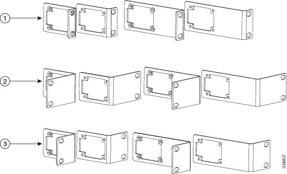
- For 19-inch racks, use part number 700-39959-01 (see “Attaching Brackets for 19-Inch Racks” section).
- For 23-inch racks, use part number 700-40065-01 (see “Attaching Brackets for 23-Inch Racks” section).
- For ETSI racks, use part number 700-40067-01 (see “Attaching Brackets for ETSI Racks” section).
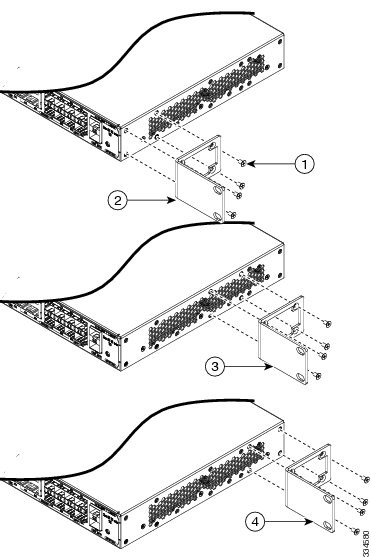
Attaching Brackets for 19-Inch Racks
Figure 3-2 shows how to attach brackets for 19-inch racks on the router.
Figure 3-2 Attaching Brackets for 19-Inch Racks

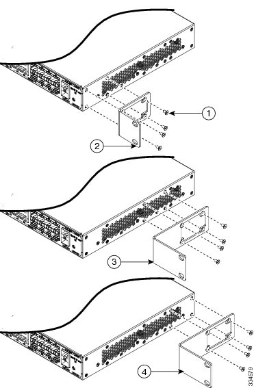
Attaching Brackets for 23-Inch Racks
Figure 3-3 shows how to attach brackets for 23-inch racks on the router.
Figure 3-3 Attaching Brackets for 23-Inch Racks
Attaching Brackets for ETSI Racks
Figure 3-4 shows how to attach brackets for ETSI racks on the router.
Figure 3-4 Attaching Brackets for ETSI Racks
Mounting the Cisco ASR 901 10G Router in a Rack
Perform the steps given below to mount the router into the equipment rack.
Note To secure the Cisco ASR 901 10G router to the equipment rack, you must use the two mounting screws (provided) for each side or follow your local practices for installing the router into your equipment rack. Ensure that the rack-mount brackets are securely fastened. For more information, see the “Attaching Brackets to the Router” section.
Step 1 Locate the equipment rack position where you plan to install the router.
Step 2 Verify that there are no obstructions and ensure that the equipment rack is stabilized.
Step 3 Determine whether you are mounting the router on a 19-inch, 23-inch, or an ETSI rack. Figure 3-1 shows the types of mounting brackets.
Step 4 Determine the mounting position (Front-, Mid-, or Rear-mounting) of the router. (For 19-inch racks, see Attaching Brackets for 19-Inch Racks. For 23-inch racks, see Attaching Brackets for 23-Inch Racks. For ETSI racks, see Attaching Brackets for ETSI Racks.)
Step 5 Locate the mounting holes of the router.
Step 6 Align the rack-mounting bracket with the router and position with the four #6-32 x 0.25-inch screws (provided).
Step 7 Insert the screws (four places) and tighten using a Number 2 Phillips screwdriver (each side).
Step 8 Position the router in the equipment rack lining up the bracket holes on the router with the holes on the rack and secure with four #6-32 x 0.25-inch mounting screws (two on each side).
Step 9 Tighten the screws using a 1/4-inch flat-blade screwdriver (each side).
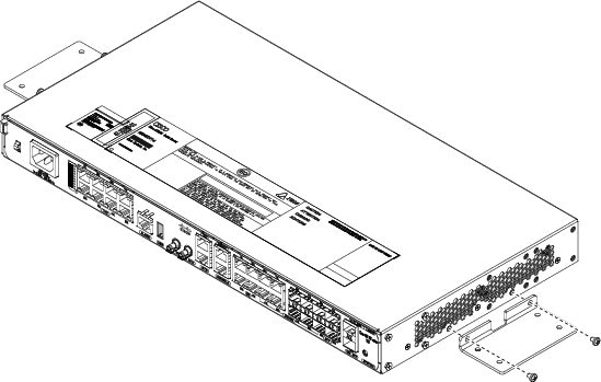
Attaching Brackets for Wall-Mounting
Perform the steps given below to attach brackets on the router for wall-mounting.
Step 1 Locate the mounting holes of the router.
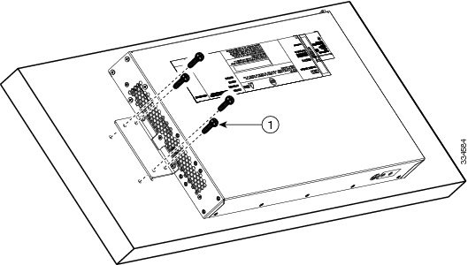
Step 2 Align the wall-mounting bracket with the router and position with the four Number 6-32 x 0.25-inch screws (provided). See Figure 3-5.
Step 3 Insert the screws (in four places) and tighten using a Number 2 Phillips screwdriver (on each side).
Step 4 Position the router in the equipment rack lining up the bracket holes on the router with the holes on the rack and secure with four Number 6-32 x 0.25-inch mounting screws (two on each side).
Step 5 Tighten the screws using a 1/4-inch flat-blade screwdriver (on each side).
Figure 3-5 Attaching 19-inch Bracket to Wall-Mount the Router
Mounting the Router on a Wall
The router can be wall mounted with the ports either facing up or down. The illustration used in the procedure below uses the orientation of ports facing upwards.
For the best support of the router and cables, make sure that the switch is attached securely to wall studs or to a firmly attached plywood mounting backboard.
Perform the steps given below:
Warning Read the wall-mounting instructions carefully before beginning installation. Failure to use the correct hardware or to follow the correct procedures could result in a hazardous situation to people and damage to the system. Statement 378
Step 1 Locate the position where you plan to install the router.
Step 2 Ensure that there are no obstructions.
Step 3 Position the router with the ports facing up as in Figure 3-6, or down and align the bracket holes with the holes on the wall and secure with four Number 6-32 x 0.25-inch mounting screws (two on each side).
Step 4 Tighten the screws using a 1/4-inch flat-blade screwdriver (each side).
Figure 3-6 Mounting the Router on a Wall
Connecting the Chassis Ground and Power
Before you connect power or turn on power to the Cisco ASR 901 10G router, you must provide an adequate chassis ground (earth) connection to your router.
Grounding the Cisco ASR 901 10G Router
The Cisco ASR 901 10G router provides a grounding point on the rear of the unit for a 2-hole lug.
To ensure the chassis ground connection that you provide is adequate, you need the following parts and tools:
- Ratcheting torque screwdriver with Phillips head that exerts up to 15 pound-force inches (lbf-in) of pressure for attaching the ground wire to the router.
- Crimping tool as specified by the ground lug manufacturer
- 16-AWG copper wire for the power cord
- Appropriate wire-stripping tools
Warning This equipment must be grounded. Never defeat the ground conductor or operate the equipment in the absence of a suitably installed ground conductor. Contact the appropriate electrical inspection authority or an electrician if you are uncertain that suitable grounding is available. Statement 1024
Warning Use copper conductors only. Statement 1025
Warning When installing the unit, the ground connection must always be made first and disconnected last. Statement 42
Figure 3-7 shows the grounding point marked on the rear panel of the Cisco ASR 901 10G router for ease of installation
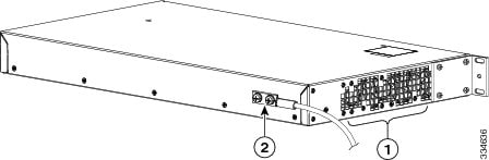
This unit is to be installed in a restrictive access location and must be permanently grounded to minimum 6-AWG copper ground wire.
Perform the steps given below to ground the Cisco ASR 901 10G router using a 2-hole lug and the corresponding mounting point. Most carriers require a 6-AWG ground connection. Verify your carrier’s requirements for the ground connection.
Step 1 In the accessory kit, locate the 2-hole lug, 2 pan-head Phillips head screws used to attach the lug to the router, and the 6-AWG ground wire. (Lug, screws, and wire are part number 32-0629-01.)
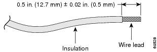
Step 3 If your ground wire is insulated, use a wire-stripping tool to strip the ground wire to 0.5 inch ± 0.02 inch (12.7 mm ±0.5 mm) for the ring terminal (Figure 3-8).
Figure 3-8 Stripping a Ground Wire
Step 4 Slide the open end of the ground lug over the exposed area of the ground wire.
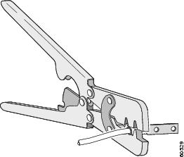
Step 5 Using a crimping tool (as specified by the ground lug manufacturer), crimp the ground lug to the ground wire (Figure 3-9).
Figure 3-9 Crimping a Ground Lug onto the Ground Wire
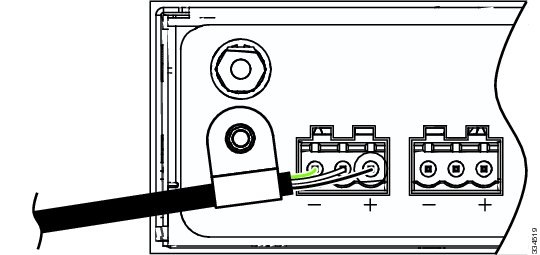
Step 6 Use a Phillips head screwdriver to attach the ground lug and wire assembly to the front of the router with the two screws from the accessory kit.
Step 7 Connect the other end of the ground wire to a suitable grounding point at your site.
Power Connection Compliance
Warning Before performing any of the following procedures, ensure that power is removed from the DC circuit. Statement 1003
Warning Use copper conductors only. Statement 1025
Note The installation must comply with the 2002 National Electric Code (NEC) and other applicable codes.
Wiring the DC-Input Power Source
Note Before connecting the DC-input power source, you should install cable holders in front of the chassis. See “$paratext>” section on how to install cable holders.
Warning This product relies on the building’s installation for short-circuit (overcurrent) protection. Ensure that the protective device is rated not greater than 10 A minimum, 60 VDC. Statement 1005
Complete the following steps to connect the DC power supply to the Cisco ASR 901 10G router:
Step 1 Switch off the DC power source at the circuit breaker, and place the circuit breaker in the Off position.
Step 2 Locate the two 3-pin terminal blocks (part number 27-1892-01). The terminal blocks are located in the accessory kit (part number 53-3438-01) shipped with the Cisco ASR 901 10G router.
Step 3 Plug the 3-pin terminal block into the power connector located on the front side of the router. See Figure 3-10
Figure 3-10 3-Pin Terminal Block
Step 4 Repeat Step 3 to attach the other terminal block.
Step 5 Connect the other end of the power cord to the site DC power source.
Warning An exposed wire lead from a DC-input power source can conduct harmful levels of electricity. Be sure that no exposed portion of the DC-input power source wire extends from the terminal block plug. Statement 122
Warning When installing this unit, secure all power cabling to avoid disturbing field-wiring connections. Statement 38
Installing the DC Power Cord Retainer
You must install the two cable holders in front of the chassis before connecting the DC-input power source. The DC-input wire should go through the cable holder before the screw is fastened.
Complete the following steps to install the cable holders to the Cisco ASR 901 10G router.
Step 1 In the accessory kit, locate the two cable holders and the two pan-head Phillips head screws used to attach the cable holders to the router. (part number of cable holder is 52-0685-01.)
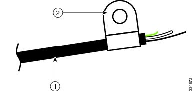
Step 3 Insert the DC power cord through the cable holder. See Figure 3-11. Repeat this step for the second DC power cord.
Figure 3-11 Inserting the DC Power Cord Through Cable Holder
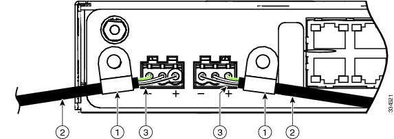
Step 4 Use a Phillips head screwdriver to attach the cable holders to the front of the router with the two screws from the accessory kit. See Figure 3-12.
Figure 3-12 Attaching Cable Holder to the Router
Installing the AC Power Cord Retainer
Complete the following steps to install the AC power cord retainer to the Cisco ASR 901 10G router using the corresponding mounting point.
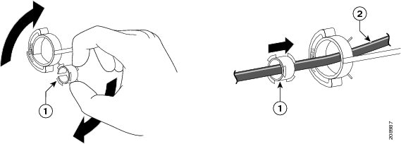
Step 1 Choose the sleeve size of the power cord retainer based on the thickness of the cord. The smaller sleeve can be snapped off and used for thin cords. See Figure 3-16.
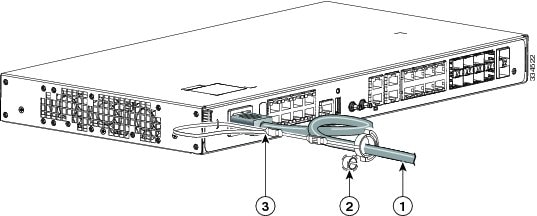
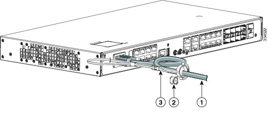
Step 2 Slide the retainer around the AC power cord, and pass it around the lanced loop on the router. See Figure 3-13.
Figure 3-13 Inserting the Retainer through the Lanced Loop
Step 3 Slide the retainer through the first latch. See Figure 3-14.
Figure 3-14 Sliding the Retainer Through the Latch
Step 4 Slide the retainer through the other latches to lock it. See Figure 3-15.
Figure 3-15 Locking the Retainer
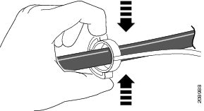
Step 5 (Optional) Use the small sleeve for thin power cords. Use the small sleeve to provide greater stability for thin cords. Detach the sleeve, and slide it over the power cord. See Figure 3-16.
Figure 3-16 Sleeve Around the Power Cord
Step 6 Secure the AC power cord by pressing the retainer. See Figure 3-17.
Figure 3-17 Securing the Power Cord in the Retainer
Installing and Removing SFP Modules
This section describes how to install and remove SFP modules. The modules are inserted into the SFP module slots on the front of the Cisco ASR 901 10G router. These field-replaceable modules provide interfaces.
For a list of supported SFP modules, see the Release Notes for Cisco ASR 901 Series Aggregation Services Router . Each port must match the wavelength specifications on the other end of the cable. For reliable communications, the cable must not exceed 328 feet (100 meters).
For detailed instructions on installing, removing, and cabling the SFP module, see the SFP module documentation.
Note The installation and removal steps given for SFP modules are also applicable for SFP+ modules.
Installing SFP Modules
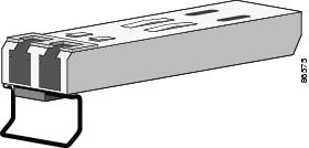
Figure 3-18 shows an SFP module that has a bale-clasp latch.
Figure 3-18 SFP Module with a Bale-Clasp Latch
Complete the following steps to insert an SFP module into the module slot:
Step 1 Attach an ESD-preventive wrist strap to your wrist and to a bare metal surface on the chassis.
Some SFP modules identify the top side of the module with transmit (TX) and receive (RX) markings or arrows that show the direction of the connection.
Step 2 If the SFP module that you are using has the markings, use them to identify the top side of the module.
Step 3 Align the SFP module in front of the slot opening.
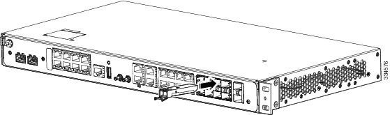
Step 4 Insert the SFP module into the slot until you feel the connector on the module snap into place in the rear of the slot (see Figure 3-19).
Figure 3-19 Installing an SFP Module into an SFP Module Slot
Step 5 For fiber-optic SFP modules, remove the dust plugs from the optical ports, and store them for later use.
Step 6 Insert the cable connector into the SFP module:
- For fiber-optic SFP modules, insert the line card or MT-RJ cable connector into the SFP module.
- For copper 1000BASE-T SFP modules, insert the RJ-45 cable connector into the SFP module.
Removing SFP Modules
Complete the following steps to remove an SFP module from a module receptacle:
Step 1 Attach an ESD-preventive wrist strap to your wrist and to a bare metal surface on the chassis.
Step 2 Disconnect the cable from the SFP module, and insert a dust plug into the cable end.

Tip For reattachment, note which cable connector plug is transmit (TX) and which is receive (RX).
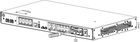
Step 3 Unlock and remove the SFP module, as shown in Figure 3-20.
If the module has a bale-clasp latch, pull the bale out and down to eject the module. If the bale-clasp latch is obstructed and you cannot use your index finger to open it, use a small, flat-blade screwdriver or other long, narrow instrument to open the bale-clasp latch.
Figure 3-20 Removing a Bale-Clasp Latch SFP Module by Using a Flat-Blade Screwdriver
Step 4 Grasp the SFP module between your thumb and index finger, and carefully remove it from the module slot.
Step 5 For fiber-optic SFP modules, insert a dust plug into the optical ports of the SFP module to keep the optical interfaces clean.
Step 6 Place the removed SFP module in an antistatic bag or any other protective casing.
Connecting Cables
This section describes how to connect the Cisco ASR 901 10G router to external devices and networks. It includes the following sections:
Connecting the Console Port
Warning Do not work on the system or connect or disconnect cables during periods of lightning activity. Statement 1001
The Cisco ASR 901 10G router has a single console port that can function in DTE mode:
Note The console port functions are asynchronous serial ports; any devices connected to the console port must be cabled for asynchronous transmission. (Asynchronous is the most common type of serial device; for example, most modems are asynchronous devices.)
The Cisco ASR 901 10G router uses RJ-45 ports for console port function.
We provide the following cables and adapters for connecting the Cisco ASR 901 10G router to a console terminal:
Types of RJ-45 Cables
Cisco products use the following types of RJ-45 cables:
The Cisco ASR 901 10G router ships with and uses the rollover cable. For instructions on how to identify a rollover cable, see Identifying a Rollover Cable.
Console Port
Complete the following steps to connect a terminal or a PC running terminal emulation software to the console port on the router:
Step 1 Connect the terminal using an RJ-45 rollover cable and an RJ-45-to-DB-25 or RJ-45-to-DB-9 adapter (labeled TERMINAL) to the console port. For cable pinouts, see the “Console Port Signals and Pinouts” section.
Note The RJ-45-to-DB-25 adapter (Cisco part number 29-0810-01) can be purchased from Cisco Systems.
Step 2 Configure the terminal or terminal emulation software for 9600 baud, 8 data bits, no parity, and 2 stop bits.
Note Hardware flow control is not possible on the console port.
Connecting the Network Cables
This section describes how to connect the following router interfaces:
Connecting Gigabit Ethernet Interface Cables
The RJ-45 port supports standard straight-through and crossover Category 5 unshielded twisted-pair (UTP) cables. Cisco Systems does not supply Category 5 UTP cables; these cables are available commercially.
Complete the following steps to connect the cable to the router Gigabit Ethernet port:
Step 1 Ensure the router is powered off.
Step 2 Connect one end of the cable to the GE port on the router.
Step 3 Connect the other end to the BTS patch or demarcation panel at your site.
For more information about Gigabit Ethernet connectors including pinouts, see “Gigabit Ethernet Connector Pinouts” section
Connecting T1 and E1 Interface Cables
Complete the following steps to connect the cable to a router T1/E1 port:
Note You must close the relays on the card using the standalone subcommand. For more information, see the Cisco ASR 901 Series Aggregation Services Router Software Configuration Guide.
Step 1 Ensure the router is powered off.
Step 2 Connect one end of the cable to the T1 or E1 (RJ-48C) port. Use a T1/E1 cable.
Step 3 Connect the other end to the BTS patch or demarcation panel at your site.
Step 4 Turn on power to the router (see “Powering on the Router” section for more details).
For more information about T1/E1 connectors including pinouts, see “T1/E1 Port Pinouts” section.
Connecting SFP Cables
Complete these steps to connect the cable to a router SFP port.
Step 1 Ensure the router is powered off.
Step 2 Insert the SFP module patch cable into the slot until you feel the connector on the cable snap into place in the rear of the slot.
Step 3 Connect the other end to the patch or demarcation panel at your site.
Step 4 Turn on power to the router (see “Powering on the Router” section for more details).
For more information about SFP connectors, see “SFP and SFP+ Port Pinouts and Cable Specifications” section.
Connecting Cables to the BITS Interface
Complete these steps to connect the cable to the router BITS port:
Step 1 Ensure the router is powered off.
Step 2 Connect one end of the cable to the BITS port using a T1/E1 cable.
Step 3 Connect the other end to the SETS unit.
Step 4 Turn on power to the router (see “Powering on the Router” section for more details).
For more information about T1/E1 connectors including pinouts, see “BITS Port Pinouts” section.
Connecting GPS Cables
The following sections describe how to connect cables from the Cisco ASR 901 10G router to a GPS unit for input or output timing or frequency.
Connecting Cables to the 10Mhz or 1PPS Interface
Complete these steps to connect cables to the 10Mhz or 1PPS interface:
Step 1 Ensure the router is powered off.
Step 2 Connect one end of a mini-coax cable to the GPS unit.
Step 3 Connect the other end of the mini-coax cable to the 10Mhz or 1PPS port on the Cisco ASR 901 10G router.
For instructions on how to configure clocking, see the Cisco ASR 901 Series Aggregation Services Router Software Configuration Guide.
For more information about 10Mhz and 1PPS port pinouts, see “GPS Port Pinouts” section.
Connecting Cables to the ToD Interface
Complete these steps to connect cables to the ToD interface for GPS timing.
Step 1 Ensure the router is powered off.
Step 2 Connect one end of a straight-through Ethernet cable to the GPS unit.
Step 3 Connect the other end of the cable to the ToD port on the Cisco ASR 901 10G router.
For instructions on how to configure clocking, see the Cisco ASR 901 Series Aggregation Services Router Software Configuration Guide.
Note For more information about BITS port pinouts, see “Time of Day Pinouts” section.
Connecting to Alarm Port
Use a straight cable to connect to the alarm port. For details on the pinouts, see “Alarm Port Pinouts” section.
Connecting to the Management Ethernet Port
Use a straight or a cross over ethernet cable to connect to the management ethernet port. For details on the pinouts, see “Management Ethernet Port Pinouts” section.
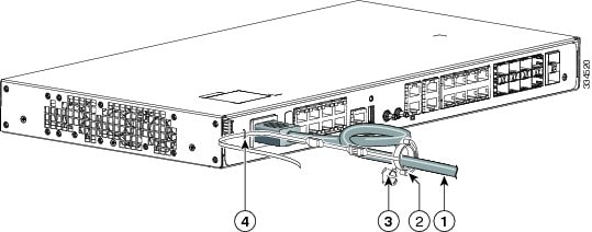
Dressing Router Cables
Ensure all Cisco router cables are properly insulated so as not to interfere with each other or other pieces of equipment. Use local practices to ensure that the cables attached to your router are properly insulated.
Note If your Cisco ASR 901 10G router is front-mounted, you can use the cable guide (found in the accessory kit) to dress the cables.
To continue the installation, proceed to the next section, “Powering on the Router.”
Powering on the Router
Warning Do not touch the power supply when the power cord is connected. For systems with a power switch, line voltages are present within the power supply even when the power switch is off and the power cord is connected. For systems without a power switch, line voltages are present within the power supply when the power cord is connected. Statement 4
Warning This equipment is intended to be grounded. Ensure that the host is connected to earth ground during normal use. Statement 39
Interpreting Front-Panel LEDs
The Cisco ASR 901 10G router provides a number of LEDs on the front panel to monitor conditions and to aid in troubleshooting problems. For a description of the LEDs, see the “Reading the LEDs” section.
Power-On Procedure
Complete these steps to power on the Cisco ASR 901 10G router and verify its initialization and self-test:
Step 1 Remove the tape from the circuit breaker switch handle.
Step 2 Restore power by moving the handle of the circuit breaker to the ON position.
The LED (labeled POWER) on the front panel should go ON and the fans should begin to operate.
Depending on your installation, other front-panel LEDs can also come on.
Note When the Cisco ASR 901 10G router (DC unit) is powered ON, it takes about 30 seconds for the system LED to turn ON.
Note If you encounter problems when you power on the router, see Appendix A, “Troubleshooting”.
Formatting Procedures for Flash Memory
We recommend that you erase the (Class B) flash memory to initialize with a Class B flash file system.
The Class B flash file system is also known as the low end file system (LEFS).
Formatting Flash Memory as a DOS File System
To format the flash memory, or to remove the files from it, use the erase flash: command.
The following is sample output for formatting the flash memory, formatted with a Class B flash file system:
File and Directory Procedures
The following sections describe file and directory procedures for flash memory, formatted with a Class B flash file system.
Copying Files
To copy files to another location, use the copy tftp:flash: command.
The following is sample output for copying the file from an external location to the internal flash memory.
Displaying Contents of the Flash Memory
To display the contents (directories and files) of the flash memory formatted with a Class B flash file system, use the dir: command.
The following is sample output for displaying the contents of the flash memory with a Class B flash file system:
Deleting Files from the Flash Memory
To delete a file from the flash memory, use the delete: filename command followed by the squeeze flash: command.
When a file is deleted in the Class B flash file system, the memory space occupied by the deleted file is not released until you use the squeeze command. Although the memory space once occupied by the deleted file remains, the deleted file cannot be recovered. To release the memory space occupied by a deleted file, enter the squeeze flash: command
The following is sample output for deleting a Cisco IOS file from the flash memory, and releasing the memory space originally occupied by the file.
Displaying File Content
To display the contents of a file in the flash memory, use the more flash: filename command.
The following is sample output from the more flash command on a flash card:
 Feedback