Cisco ASR 901 10G Series Aggregation Services Router Hardware Installation Guide
Bias-Free Language
The documentation set for this product strives to use bias-free language. For the purposes of this documentation set, bias-free is defined as language that does not imply discrimination based on age, disability, gender, racial identity, ethnic identity, sexual orientation, socioeconomic status, and intersectionality. Exceptions may be present in the documentation due to language that is hardcoded in the user interfaces of the product software, language used based on RFP documentation, or language that is used by a referenced third-party product. Learn more about how Cisco is using Inclusive Language.
- Updated:
- July 16, 2014
Chapter: Cable Specifications
Cable Specifications
If you prefer to build your own cables, this appendix provides cable specifications for the Cisco ASR 901 10G router.
The appendix includes the following sections:
- Gigabit Ethernet Connector Pinouts
- SFP and SFP+ Port Pinouts and Cable Specifications
- T1/E1 Port Pinouts
- Console Port Signals and Pinouts
- BITS Port Pinouts
- Time of Day Pinouts
- GPS Port Pinouts
- Alarm Port Pinouts
- Management Ethernet Port Pinouts
- Auxiliary Port

Warning![]() To comply with the Telcordia GR-1089 NEBS standard for electromagnetic compatibility and safety, use only shielded cables that are grounded on both ends for Type 2 and Type 4 ports that require shielded cables.
To comply with the Telcordia GR-1089 NEBS standard for electromagnetic compatibility and safety, use only shielded cables that are grounded on both ends for Type 2 and Type 4 ports that require shielded cables.
Gigabit Ethernet Connector Pinouts
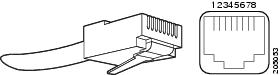
This section illustrates the Gigabit Ethernet RJ-45 connector and lists its pinout and signal descriptions.

Note![]() The RJ-45 ports are capable of operating in both 100BaseT and 1000BaseT modes.
The RJ-45 ports are capable of operating in both 100BaseT and 1000BaseT modes.
Figure B-1 shows the RJ-45 connector and port, and Table B-1 lists the connector pinouts and signals.
Figure B-1 RJ-45 Connector and Port
|
|
|
|
|---|---|---|
SFP and SFP+ Port Pinouts and Cable Specifications
For information about SFP and SFP+ modules supported by the Cisco ASR 901 10G router, including pinouts, see the Connector and Cable Specifications document on Cisco.com.
Note![]() Pins not listed in the tables in this appendix are not connected.
Pins not listed in the tables in this appendix are not connected.
T1/E1 Port Pinouts
Figure B-2 shows the RJ-48C connector used by the T1/E1 ports on the TDM interface module on the Cisco ASR 901 10G router.
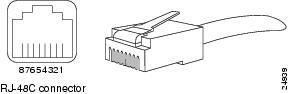
Figure B-3 shows the RJ-48C connector wiring for the T1/E1 cable.
Figure B-3 RJ-48-to-RJ-48 T1/E1 Cable Wiring
Note![]() We recommend using a shielded cable for RJ-48C connectors.
We recommend using a shielded cable for RJ-48C connectors.
Table B-2 shows the pinout configuration for the RJ-48C connectors on the Cisco ASR 901 10G router for both the shielded and unsaddled cables for either T1 or E1. Table B-2 shows the pinout configuration for the RJ-45 connectors on the TDM interface module on the Cisco ASR 901 10G router.
|
|
|
|
|
|---|---|---|---|
Console Port Signals and Pinouts
The Cisco ASR 901 10G router ships with a console cable kit, which contains the cable and adapters to connect a console terminal (an ASCII terminal or PC running terminal emulation software). The console cable kit includes the following items:
- RJ-45-to-RJ-45 rollover cable
- RJ-45-to-DB-9 female DTE adapter (labeled TERMINAL)
- RJ-45-to-DB-25 female DTE adapter (labeled TERMINAL)
To connect a modem, you need to order an auxiliary cable.
For console connections, see the “Console Port Signals and Pinouts” section.
Console Port Signals and Pinouts
Use the thin, flat, RJ-45-to-RJ-45 rollover cable and the RJ-45-to-DB-9 female DTE adapter (labeled TERMINAL) to connect the console port to a PC running terminal emulation software. Figure B-4 shows how to connect the console port to a PC. Table B-4 lists the pinouts for the asynchronous serial console port, the RJ-45-to-RJ-45 rollover cable, and the RJ-45-to-DB-9 female DTE adapter (labeled TERMINAL).
Figure B-4 Connecting the Console Port to a PC
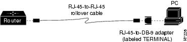
Table B-3 lists the Console port pinouts for the Cisco ASR 901 10G router.
|
|
|
|
|
|
|---|---|---|---|---|
Table B-4 describes the pinouts RJ-45-to-RJ-45 and RJ-45-to-DB-9 rollover cables.
|
|
|
|
|
|
|---|---|---|---|---|
|
|
|
|
|
|
11 |
||||
|
|
Table B-5 lists the pinouts for the asynchronous serial console port, the RJ-45-to-RJ-45 rollover cable, and the RJ-45-to-DB-25 female DTE adapter (labeled TERMINAL).
|
|
|
|
|
|
|---|---|---|---|---|
|
|
|
|
|
|
12 |
||||
|
|
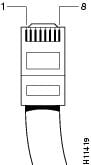
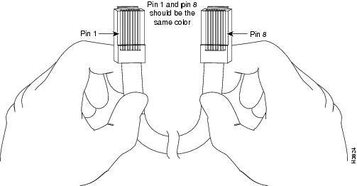
Identifying a Rollover Cable
To identify a rollover cable, compare the modular plugs at the two ends of the cable. When you hold the plugs side by side, with the tab at the back, the wire connected to the pin on the outside of the left plug should be the same color as the wire connected to the pin on the outside of the right plug (Figure B-5.) If you purchased your cable from Cisco Systems, pin 1 is white on one connector, and pin 8 is white on the other (a rollover cable connects pins 1 and 8, 2 and 7, 3 and 6, and 4 and 5).
Figure B-5 Identifying a Rollover Cable
BITS Port Pinouts
Table B-6 list the pinouts for the BITS interface RJ-45 port on the Cisco ASR 901 10G router.
|
|
|
|
|
|---|---|---|---|
Time of Day Pinouts
Table B-6 list the pinouts for the Time of Day RJ-45 interface on the Cisco ASR 901 10G router.
|
|
|
|
|
|---|---|---|---|
GPS Port Pinouts
The Cisco ASR 901 10G router has a 10Mhz and a 1PPS GPS port that allow you to configure input or output clocking with a GPS device. Table B-8 summarizes the pinouts for the 10Mhz and 1PPS interfaces.
Note![]() For pinouts related to ToD and 1PPS using the BITS interface, see Console Port Signals and Pinouts.
For pinouts related to ToD and 1PPS using the BITS interface, see Console Port Signals and Pinouts.
|
|
|
|
|---|---|---|
The 1PPS interface type is Series 1.0 / 2.3, 50 ohms.
For instructions on how to configure the 10 Mhz and 1PPSs ports, see the Cisco ASR 901 Series Aggregation Services Router Software Configuration Guide.
Alarm Port Pinouts
The router has four alarm inputs. The alarm setting is open or closed.
- Open means that the normal condition has current flowing through the contact (referred to as normally closed contact). The alarm is generated when the current stops.
- Closed means that no current flows through the contact (referred to as normally open contact). The alarm is generated when the current flows.
The alarm input is a dry-contact alarm port. You can connect up to four alarm inputs from devices, such as a door, a temperature gauge, or a fire alarm, to the alarm port. You can use the alarm-contact command to set the alarm severity to minor, major, or critical. An alarm generates a system message.
Note![]() External DC bias is not required for the alarm port inputs.
External DC bias is not required for the alarm port inputs.
Figure B-6 shows the RJ-45 connector pinouts used for alarm, and Table B-9 lists the connector pinouts and signals.
Figure B-6 RJ-45 Connector Pinouts for Alarm
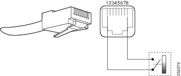
Table B-9 list the pinouts for the alarm port (RJ45) on the Cisco ASR 901 10G router.
|
|
|
|
|---|---|---|
Management Ethernet Port Pinouts
Table B-10 list the pinouts for the management ethernet port (RJ-45) on the Cisco ASR 901 10G router.
|
|
|
|
|---|---|---|
Auxiliary Port
Auxiliary port is not supported on the Cisco ASR 901 10G router and you should not try to configure the auxiliary port.
 Feedback