Hardware Specifications

Ultra M deployments use the following hardware:


Note


The specific component software and firmware versions identified in the sections that follow have been validated in this Ultra M solution release.

Cisco Catalyst Switches

Cisco Catalyst Switches provide as physical layer 1 switching for Ultra M components to the management and provisioning networks. One of two switch models is used based on the Ultra M model being deployed:

Catalyst C2960XR-48TD-I Switch

The Catalyst C2960XR-48TD-I has 48 10/100/1000 ports.

Table 1. Catalyst 2960-XR Switch Information

Ultra M Model(s)

Quantity

Software Version

Firmware Version

Ultra M XS Single VNF

2

IOS 15.2.(2) E5

Boot Loader: 15.2(3r)E1

Ultra M XS Multi-VNF

1 per rack

IOS 15.2.(2) E5

Boot Loader: 15.2(3r)E1

Catalyst 3850-48T-S Switch

The Catalyst 3850 48T-S has 48 10/100/1000 ports.

Table 2. Catalyst 3850-48T-S Switch Information

Ultra M Models

Quantity

Software Version

Firmware Version

Ultra M XS Single VNF

2

IOS: 03.06.06E

Boot Loader: 3.58

Ultra M XS Multi-VNF

1 per Rack

IOS: 03.06.06E

Boot Loader: 3.58

Cisco Nexus Switches

Cisco Nexus Switches serve as top-of-rack (TOR) leaf and end-of-rack (EOR) spine switches provide out-of-band (OOB) network connectivity between Ultra M components. Two switch models are used for the various Ultra M models:

Nexus 93180-YC-EX

Nexus 93180 switches serve as network leafs within the Ultra M solution. Each switch has 48 10/25-Gbps Small Form Pluggable Plus (SFP+) ports and 6 40/100-Gbps Quad SFP+ (QSFP+) uplink ports.

Table 3. Nexus 93180-YC-EX

Ultra M Model(s)

Quantity

Software Version

Firmware Version

Ultra M XS Single VNF

2

NX-OS: 7.0(3)I7(3)

BIOS: 7.59

Ultra M XS Multi-VNF

2 per Rack

NX-OS: 7.0(3)I7(3)

BIOS: 7.59

Nexus 9236C

Nexus 9236 switches serve as network spines within the Ultra M solution. Each switch provides 36 10/25/40/50/100 Gbps ports.

The following table provides the Nexus switch recommendation for both Ultra M B1.0 and B1.1 models.

Table 4. Nexus 9236C

Ultra M Model(s)

Quantity

Software Version

Firmware Version

Ultra M XS Single VNF

2

For Ultra M B1.0 model — NX-OS: 7.0(3)I7(3)

For Ultra M B1.1 model — NX-OS: 7.0(3)I7(4)

For Ultra M B1.0 model — BIOS: 7.59

For Ultra M B1.1 model — BIOS: 7.61

Ultra M XS Multi-VNF

2

For Ultra M B1.0 model — NX-OS: 7.0(3)I7(3)

For Ultra M B1.1 model — NX-OS: 7.0(3)I7(4)

For Ultra M B1.0 model — BIOS: 7.59

For Ultra M B1.1 model — BIOS: 7.61

UCS C-Series Servers

Cisco UCS C240 M4S SFF servers and host the functions and virtual machines (VMs) required by Ultra M.

Server Functions and Quantities

Server functions and quantity differ depending on the Ultra M model you are deploying:

  • Ultra M Manager Node: Required only for Ultra M models based on the Hyper-Converged architecture, this server hosts the following:

    • OSP-D VM

  • OpenStack Controller Nodes: These servers host the high availability (HA) cluster that serves as the VIM within the Ultra M solution. In addition, they facilitate the Ceph storage monitor function required by the Ceph Storage Nodes and/or OSD Compute Nodes.

  • OSD Compute Nodes: Required only for Hyper-converged Ultra M models, these servers provide Ceph storage functionality in addition to hosting VMs for the following:

    • Elastic Services Controller (ESC) Virtual Network Function Manager (VNFM) active and standby VMs

    • Ultra Element Manager (UEM) VM HA cluster

    • Ultra Service Platform (USP) Control Function (CF) active and standby VMs

  • Compute Nodes: For all Ultra M models, these servers host the active, standby, and demux USP Service Function (SF) VMs.

VM Deployment per Node Type

Server Configurations

Table 5. Hyper-Converged Ultra M Single and Multi-VNF UCS C240 M4 Server Specifications by Node Type

Node Type

CPU

RAM

Storage

Software Version

Firmware Version

Ultra M Manager Node*

2x 2.60 GHz

4x 32GB DDR4-2400-MHz RDIMM/PC4

2x 1.2 TB 12G SAS HDD

Controller

2x 2.60 GHz

4x 32GB DDR4-2400-MHz RDIMM/PC4

2x 1.2 TB 12G SAS HDD

Compute

2x 2.60 GHz

8x 32GB DDR4-2400-MHz RDIMM/PC4

2x 1.2 TB 12G SAS HDD

OSD Compute

2x 2.60 GHz

8x 32GB DDR4-2400-MHz RDIMM/PC4

4x 1.2 TB 12G SAS HDD

2x 300G 12G SAS HDD HDD

1x 480G 6G SAS SATA SSD

* OSP-D is deployed as a VM on the Ultra M Manager Node for Hyper-Converged Ultra M model(s).

Storage

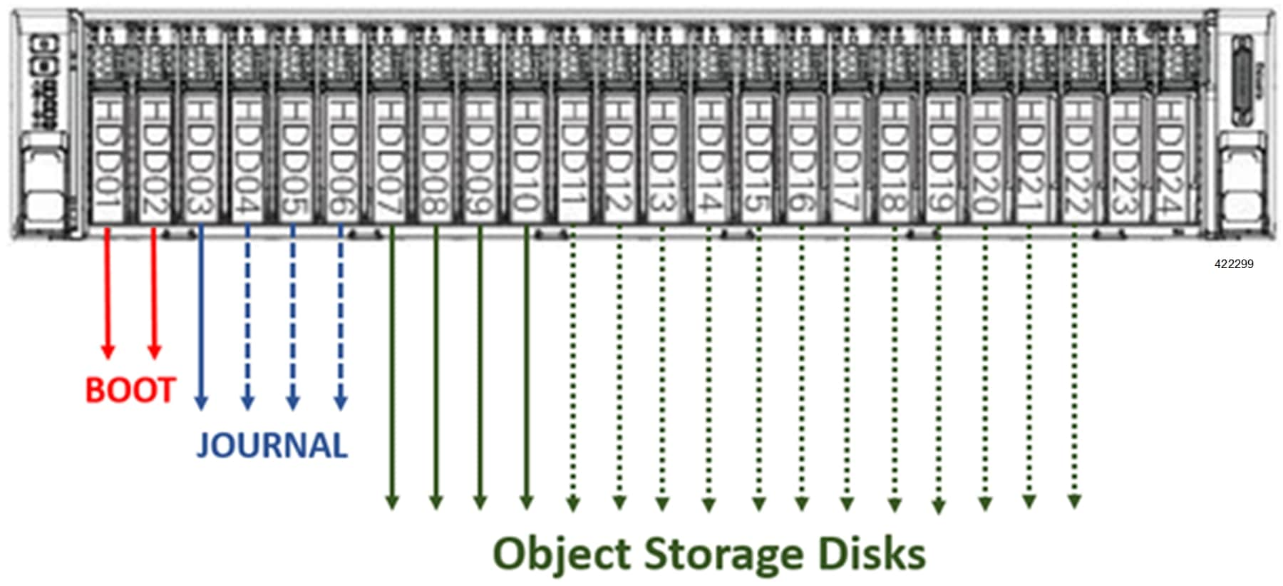
UCS C240 Front-Plane displays the storage disk layout for the UCS C240 series servers used in the Ultra M solution.

Figure 1. UCS C240 Front-Plane

NOTES:

  • The Boot disks contain the operating system (OS) image with which to boot the server.

  • The Journal disks contain the Ceph journal file(s) used to repair any inconsistencies that may occur in the Object Storage Disks.

  • The Object Storage Disks store object data for USP-based VNFs.

  • Ensure that the HDD and SSD used for the Boot Disk, Journal Disk, and object storage devices (OSDs) are available as per the Ultra M BoM and installed in the appropriate slots as identified in Table 1.

Table 6. UCS C240 M4S SFF Storage Specifications by Node Type

Ultra M Manager Node and Staging Server

2 x 1.2 TB HDD – For Boot OS configured as Virtual Drive in RAID1 – placed on Slots 1 & 2

Controllers, Computes

2 x 1.2 TB HDD – For Boot OS configured as Virtual Drive in RAID1 – placed on Slots 1 & 2

2 x 300 GB HDD – For Boot OS configured as Virtual Drive in RAID1 – placed on Slots 1 & 2

1 x 480 GB SSD – For Journal Disk as Virtual Drive in RAID0 – Slot 3

(Reserve for SSD Slot 3, 4, 5, 6 future scaling needs)

4 x 1.2 TB HDD – For OSD’s configured as Virtual Drive in RAID0 each – Slot 7, 8, 9, 10

(Reserve for OSD 7, 8, 9, 10…., 24)

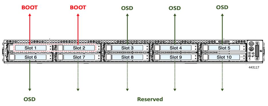
Figure 2. UCS C220 Front-Plane
  • Ensure that the RAIDs are sized such that:

    Boot Disks < Journal Disk(s) < OSDs

  • Ensure that FlexFlash is disabled on each UCS-C240 M4 (factory default).

  • Ensure that all nodes are in Unconfigured Good state under Cisco SAS RAID Controllers (factory default).