Troubleshooting
This chapter provides troubleshooting procedures for basic problems with the access point. For the most up-to-date, detailed troubleshooting information, refer to the Cisco Technical Support and Documentation website at the following URL:
http://www.cisco.com/en/US/products/hw/wireless/tsd_products_support_category_home.html
Sections in this chapter include:
•![]() Guidelines for Using the Access Points
Guidelines for Using the Access Points
•![]() Checking the Access Point LEDs
Checking the Access Point LEDs
Guidelines for Using the Access Points
You should keep these guidelines in mind when you use the access points:
•![]() The access points can only communicate with controllers and cannot operate independently.
The access points can only communicate with controllers and cannot operate independently.
•![]() The access points do not support Wireless Domain Services (WDS). The access points cannot communicate with WDS devices. However, the controller provides functionality equivalent to WDS when the access point associates to it.
The access points do not support Wireless Domain Services (WDS). The access points cannot communicate with WDS devices. However, the controller provides functionality equivalent to WDS when the access point associates to it.
•![]() The access points support Layer 2 or Layer 3 LWAPP communications with the controllers. In
The access points support Layer 2 or Layer 3 LWAPP communications with the controllers. In
Layer 2 operation, the access point and the controller must be on the same subnet and communicate with each other using MAC addresses in encapsulated Ethernet frames. This operation is not scalable to larger networks and not recommended by Cisco.
In Layer 3 operation, the access point and the controller can be on the same or different subnets. Layer 3 operation is scalable and is recommended by Cisco. A Layer 3 access point on a different subnet than the controller requires a DHCP server on the access point subnet and a route to the controller. The route to the controller must have destination UDP ports 12222 and 12223 open for LWAPP communications. The route to the primary, secondary, and tertiary controllers must allow IP packet fragments.
•![]() Before deploying your access points ensure that the following has been done:
Before deploying your access points ensure that the following has been done:
–![]() Your controllers are connected to switch ports that are configured as trunk ports
Your controllers are connected to switch ports that are configured as trunk ports
–![]() Your access points are connected to switch ports that are configured as untagged access ports
Your access points are connected to switch ports that are configured as untagged access ports
–![]() A DHCP server is reachable by your access points and has been configured with Option 43. Option 43 is used to provide the IP addresses of the Management Interface of your controllers. Typically, a DHCP server can be configured on a Cisco switch.
A DHCP server is reachable by your access points and has been configured with Option 43. Option 43 is used to provide the IP addresses of the Management Interface of your controllers. Typically, a DHCP server can be configured on a Cisco switch.
–![]() Optionally a DNS server can be configured to enable CISCO-LWAPP-CONTROLLER.<local domain> to resolve to the IP addresses of the Management Interface of your controllers.
Optionally a DNS server can be configured to enable CISCO-LWAPP-CONTROLLER.<local domain> to resolve to the IP addresses of the Management Interface of your controllers.
–![]() Your controllers are configured and reachable by the access points
Your controllers are configured and reachable by the access points
Using DHCP Option 43
You can use DHCP Option 43 to provide a list of controller IP addresses to the access points, enabling the access point to find and join a controller. For additional information, refer to the "Configuring DHCP Option 43" section.
Checking the Access Point LEDs
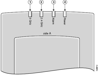
If your access point is not working properly, check the access point LEDs on the top of the unit. You can use the LED indications to quickly assess the unit's status. Figure 3-1 shows the access point LEDs (for additional information refer to the Event Log using the access point browser interface).
Figure 3-1 Access Point LEDs
|
|
5-GHz LED |
|
Alarm LED |
|
|
2.4-GHz LED |
|
Power LED |
The LED signals are listed in Table 3-1.
|
|
|
2.4 GHz LED |
5 GHz LED |
|
|---|---|---|---|---|
Off |
Off |
Off |
Off |
No power or insufficient power. Check the power source and ensure that sufficient power is supplied to the access point. See Low Power Condition. |
Off |
Red |
Off |
Off |
Power applied and access point powering up (typical 10-20 seconds). If the red Alarm LED remains on for more than 1 minute, remove power from the access point and contact TAC for assistance. |
All LEDs sequentially cycle on and off |
Access point searching for a controller or DHCP server. If the access point remains in this mode for more than 5 minutes, it is unable to find the controller. Check the connection between the access point and the controller. Also verify a DHCP server is available on the access point subnet. |
|||
Green |
Off |
Blinking Yellow |
Blinking Amber |
Normal operation, both radios transmitting beacons or transmitting and receiving data packets. If one or both radio LEDs remain off, this indicates a problem with the wireless network. Check the controller configuration for the access point. |
Green |
Off |
On or off |
Blinking Amber |
Normal operation, 5-GHz radio activity. If one or both radio LEDs remain off, this indicates a problem with the wireless network. Check the controller configuration for the access point. |
Green |
Off |
Blinking Yellow |
On or off |
Normal operation, 2.4-GHz radio activity. If one or both radio LEDs remain off, this indicates a problem with the wireless network. Check the controller configuration for the access point. |
All LEDs blink on and off simultaneously |
Associated to controller and downloading new code. |
|||
Off |
Blinking red |
Off |
Off |
Duplicate access point IP address detected. Advise your network administrator about the problem. |
Off |
Off |
Off |
Off |
No power or low power condition. |
Blinking Green |
Off |
Off |
Off |
Site survey mode on AIR-AP1010 and AIR-AP1020 |
Blinking Green |
Off |
Off |
Off |
Disconnected from root AP on AIR-AP1030. |
Low Power Condition

Warning ![]() This product must be connected to a Power over Ethernet (PoE) IEEE 802.3af compliant power source or an IEC60950 compliant limited power source. Statement 353
This product must be connected to a Power over Ethernet (PoE) IEEE 802.3af compliant power source or an IEC60950 compliant limited power source. Statement 353
The access point can be powered from the 48-VDC power module or from an in-line power source. The access point supports the IEEE 802.3af power standard for in-line power sources.
For operation, the access point (powered device) requires 12 W of input power.

Note ![]() When the access point is being used in a PoE configuration, the power drawn from the power sourcing equipment (PSE), such as a switch or power injector, is higher by an amount dependent on the length of the interconnecting cable.
When the access point is being used in a PoE configuration, the power drawn from the power sourcing equipment (PSE), such as a switch or power injector, is higher by an amount dependent on the length of the interconnecting cable.
The power module (AIR-PWR-1000=) and the Cisco Aironet power injector (AIR-PWRINJ-1000af=) are capable of supplying the required operating power, but some inline power sources are not capable of supplying sufficient power. Also, some high-power inline power sources, might not be able to provide sufficient power to all ports at the same time.
Note ![]() An 802.3af compliant switch (Cisco or non-Cisco) is capable of supplying sufficient power for full operation.
An 802.3af compliant switch (Cisco or non-Cisco) is capable of supplying sufficient power for full operation.
Note ![]() If your access point is connected to in-line power, do not connect the power module to the access point.
If your access point is connected to in-line power, do not connect the power module to the access point.
On power up, the access point is placed into low power mode (both radios are deactivated), the access point power negotiation determines if sufficient power is available. If there is sufficient power then the access point begins to power up (Alarm LED is red and other LEDs are off); otherwise, the access point turns off all LEDs and remains in low power mode to prevent a possible over-current condition.
 Feedback