- Safety Information
- Warnings
- Unpacking the Access Point
- Basic Installation Guidelines
- Before Beginning the Installation
- Controller Discovery Process
- Deploying the Access Points on the Wireless Network
- Mounting Overview
- Securing the Access Point Using a Security Cable
- Connecting the Ethernet and Power Cables
- Powering Up the Access Point
- Returning MAC Information
Installing the Access Point
This chapter describes the installation of the access point and includes these sections:
•![]() Basic Installation Guidelines
Basic Installation Guidelines
•![]() Before Beginning the Installation
Before Beginning the Installation
•![]() Securing the Access Point Using a Security Cable
Securing the Access Point Using a Security Cable
•![]() Connecting the Ethernet and Power Cables
Connecting the Ethernet and Power Cables
Safety Information
Follow the guidelines in this section to ensure proper operation and safe use of the access point.
FCC Safety Compliance Statement
The FCC with its action in ET Docket 96-8 has adopted a safety standard for human exposure to radio frequency (RF) electromagnetic energy emitted by FCC certified equipment. When used with approved Cisco Aironet antennas, Cisco Aironet products meet the uncontrolled environmental limits found in OET-65 and ANSI C95.1, 1991. Proper installation of this radio according to the instructions found in this manual will result in user exposure that is substantially below the FCC recommended limits.
General Safety Guidelines
Do not hold any component containing a radio so that the antenna is very close to or touching any exposed parts of the body, especially the face or eyes, while transmitting.
Warnings
Translated versions of all safety warnings are available in the safety warning document that shipped with your access point or on Cisco.com. To browse to the document on Cisco.com, refer to "Translated Safety Warnings" for instructions.

Warning ![]() This warning symbol means danger. You are in a situation that could cause bodily injury. Before you work on any equipment, be aware of the hazards involved with electrical circuitry and be familiar with standard practices for preventing accidents. Use the statement number provided at the end of each warning to locate its translation in the translated safety warnings that accompanied this device. Statement 1071
This warning symbol means danger. You are in a situation that could cause bodily injury. Before you work on any equipment, be aware of the hazards involved with electrical circuitry and be familiar with standard practices for preventing accidents. Use the statement number provided at the end of each warning to locate its translation in the translated safety warnings that accompanied this device. Statement 1071
SAVE THESE INSTRUCTIONS
Warning ![]() Do not operate your wireless network device near unshielded blasting caps or in an explosive environment unless the device has been modified to be especially qualified for such use.
Do not operate your wireless network device near unshielded blasting caps or in an explosive environment unless the device has been modified to be especially qualified for such use.
Statement 245B
Warning ![]() In order to comply with FCC radio frequency (RF) exposure limits, antennas should be located at a minimum of 7.9 inches (20 cm) or more from the body of all persons. Statement 332
In order to comply with FCC radio frequency (RF) exposure limits, antennas should be located at a minimum of 7.9 inches (20 cm) or more from the body of all persons. Statement 332
Warning ![]() This product must be connected to a power-over-ethernet (PoE) IEEE 802.3af compliant power source or an IEC60950 compliant limited power source. Statement 353
This product must be connected to a power-over-ethernet (PoE) IEEE 802.3af compliant power source or an IEC60950 compliant limited power source. Statement 353
Warning ![]() Read the installation instructions before you connect the system to its power source. Statement 1004
Read the installation instructions before you connect the system to its power source. Statement 1004
Warning ![]() This product relies on the building's installation for short-circuit (overcurrent) protection. Ensure that the protective device is rated not greater than: 20A Statement 1005
This product relies on the building's installation for short-circuit (overcurrent) protection. Ensure that the protective device is rated not greater than: 20A Statement 1005
Unpacking the Access Point
Follow these steps to unpack the access point:
Step 1 ![]() Open the shipping container and carefully remove the contents.
Open the shipping container and carefully remove the contents.
Step 2 ![]() Return all packing materials to the shipping container and save it.
Return all packing materials to the shipping container and save it.
Step 3 ![]() Ensure that all items listed in the "Package Contents" section are included in the shipment. Check each item for damage. If any item is damaged or missing, notify your authorized Cisco sales representative.
Ensure that all items listed in the "Package Contents" section are included in the shipment. Check each item for damage. If any item is damaged or missing, notify your authorized Cisco sales representative.
Package Contents
Each access point package contains the following items:
•![]() Cisco Aironet 1000 series lightweight access point
Cisco Aironet 1000 series lightweight access point
•![]() Ceiling mount kit (ceiling-mount base, two ceiling-mount clips, two screws, and two washers)
Ceiling mount kit (ceiling-mount base, two ceiling-mount clips, two screws, and two washers)
•![]() Quick Start Guide: Cisco Aironet 1000 Series Lightweight Access Points
Quick Start Guide: Cisco Aironet 1000 Series Lightweight Access Points
•![]() Translated Safety Warnings for Cisco Aironet 1000 Series Lightweight Access Points
Translated Safety Warnings for Cisco Aironet 1000 Series Lightweight Access Points
•![]() Cisco product registration and Cisco documentation feedback cards
Cisco product registration and Cisco documentation feedback cards
Basic Installation Guidelines
Because the access point is a radio device, it is susceptible to interference that can reduce throughput and range. Follow these basic guidelines to ensure the best possible performance:
•![]() Ensure a site survey has been performed to determine the optimum placement of access points. Refer to the Cisco Aironet 1000 Series Lightweight Access Point Deployment Guide for site survey information.
Ensure a site survey has been performed to determine the optimum placement of access points. Refer to the Cisco Aironet 1000 Series Lightweight Access Point Deployment Guide for site survey information.
•![]() Check the latest release notes to ensure that your controller software version supports the access points to be installed. You can find the controller release notes by selecting your controller under Wireless LAN Controllers at this URL:
Check the latest release notes to ensure that your controller software version supports the access points to be installed. You can find the controller release notes by selecting your controller under Wireless LAN Controllers at this URL:
http://www.cisco.com/en/US/products/hw/wireless/tsd_products_support_category_home.html
•![]() Ensure that access points are not mounted closer than 20 cm (7.9 in) from the body of all persons.
Ensure that access points are not mounted closer than 20 cm (7.9 in) from the body of all persons.
•![]() Do not mount the access point within 3 ft (91.4 cm) of metal obstructions. Refer to the Cisco Aironet 1000 Series Lightweight Access Point Deployment Guide for additional information.
Do not mount the access point within 3 ft (91.4 cm) of metal obstructions. Refer to the Cisco Aironet 1000 Series Lightweight Access Point Deployment Guide for additional information.
•![]() Install the access point away from microwave ovens. Microwave ovens operate on the same frequency as the access point and can cause signal interference.
Install the access point away from microwave ovens. Microwave ovens operate on the same frequency as the access point and can cause signal interference.
•![]() Always mount the access point vertically (standing up or hanging down).
Always mount the access point vertically (standing up or hanging down).
•![]() Do not mount the access point outside of buildings.
Do not mount the access point outside of buildings.
•![]() Do not mount the access points on building perimeter walls unless outside coverage is desired.
Do not mount the access points on building perimeter walls unless outside coverage is desired.
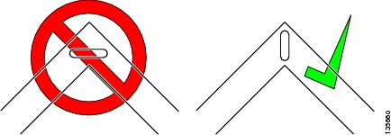
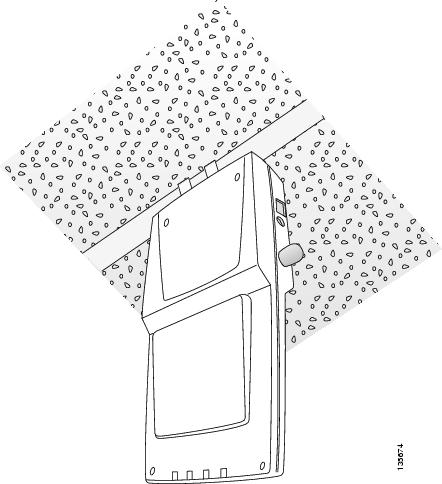
•![]() When mounting an access point in the corner of a right-angle hallway intersection, mount the access point at a 45-degree angle to the two hallways (see Figure 2-1). The access point internal antennas are not omnidirectional and cover a larger area when mounted this way.
When mounting an access point in the corner of a right-angle hallway intersection, mount the access point at a 45-degree angle to the two hallways (see Figure 2-1). The access point internal antennas are not omnidirectional and cover a larger area when mounted this way.
Figure 2-1 Mounting the Access Point in the Correct Direction
•![]() Ensure that the access point is on the same subnet as the primary, secondary, or tertiary controllers or has a DHCP server on the subnet with a route to the controllers.
Ensure that the access point is on the same subnet as the primary, secondary, or tertiary controllers or has a DHCP server on the subnet with a route to the controllers.
Before Beginning the Installation
Before you begin the installation, review these sections to become familiar with the access point, the mounting hardware, and the deployment procedure:
•![]() Access Point Layout and Connectors
Access Point Layout and Connectors
Access Point Layout and Connectors
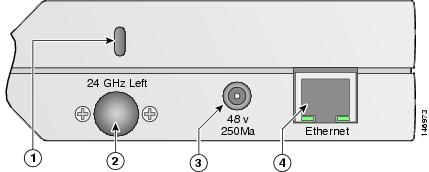
Figure 2-2 illustrates the connectors on the left side of the access point.
Figure 2-2 Access Point Left Side Connectors
|
|
Security cable keyslot |
|
48-VDC power port |
|
|
2.4-GHz antenna connector (left) |
|
Ethernet port (RJ-45) |
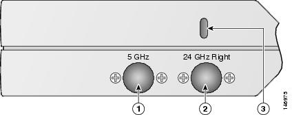
Figure 2-3 illustrates the right side of the access point.
Figure 2-3 Access Point Right Side Connectors
|
|
5-GHz antenna connector |
|
Security cable keyslot |
|
|
2.4-GHz antenna connector (right) |
||
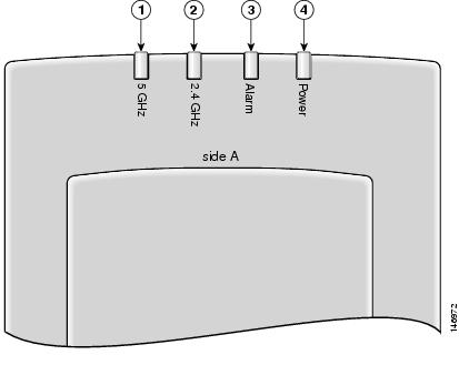
Figure 2-4 illustrates the access point LEDs on the top of the unit.
Figure 2-4 Access Point LEDs
|
|
5-GHz LED |
|
Alarm LED |
|
|
2.4-GHz LED |
|
Power LED |
Controller Discovery Process
The access point supports these controller discovery processes:
•![]() Layer 2 LWAPP discovery—Only sent on the same subnet as the access point and uses encapsulated Ethernet frames containing MAC addresses for communication between the access point and the controller. Encapsulated Ethernet frames are not suitable for Layer 3 deployments where the controller is not on the same subnet as the access points.
Layer 2 LWAPP discovery—Only sent on the same subnet as the access point and uses encapsulated Ethernet frames containing MAC addresses for communication between the access point and the controller. Encapsulated Ethernet frames are not suitable for Layer 3 deployments where the controller is not on the same subnet as the access points.
•![]() Over-the-air wireless discovery—If enabled on the controller, all the associated access points transmit wireless LWAPP neighbor messages. New access points receive the controller IP address from the wireless LWAPP neighbor messages. This feature should be disabled when all access points are installed. Also, this feature is only supported by Cisco1000 series lightweight access points and Cisco 4400 controllers.
Over-the-air wireless discovery—If enabled on the controller, all the associated access points transmit wireless LWAPP neighbor messages. New access points receive the controller IP address from the wireless LWAPP neighbor messages. This feature should be disabled when all access points are installed. Also, this feature is only supported by Cisco1000 series lightweight access points and Cisco 4400 controllers.
•![]() Locally stored controller IP addresses—If the access point was previously associated to a controller, the IP addresses of the primary, secondary, and tertiary controllers are stored in the access point non-volatile memory. The process of storing controller IP addresses in access points for later deployment is called priming the access point. For additional information, refer to the "Priming Access Points Prior to Deployment" section.
Locally stored controller IP addresses—If the access point was previously associated to a controller, the IP addresses of the primary, secondary, and tertiary controllers are stored in the access point non-volatile memory. The process of storing controller IP addresses in access points for later deployment is called priming the access point. For additional information, refer to the "Priming Access Points Prior to Deployment" section.
•![]() DHCP server discovery—Uses DHCP Option 43 to provide controller IP addresses to the access points. Cisco switches support a DHCP server option. For additional information, refer to the "Configuring DHCP Option 43" section.
DHCP server discovery—Uses DHCP Option 43 to provide controller IP addresses to the access points. Cisco switches support a DHCP server option. For additional information, refer to the "Configuring DHCP Option 43" section.
•![]() DNS server discovery—The access point uses the name CISCO-LWAPP-CONTROLLER.<local domain> to discover the controller IP addresses from a DNS server. Where <local domain> is the access point domain name.
DNS server discovery—The access point uses the name CISCO-LWAPP-CONTROLLER.<local domain> to discover the controller IP addresses from a DNS server. Where <local domain> is the access point domain name.
Cisco recommends that you configure a DHCP server with Option 43 to provide the controller IP addresses to your access points. Cisco switches provide a DHCP server option that is typically used for this purpose.
Deploying the Access Points on the Wireless Network
Prior to beginning the actual access point deployment, perform these tasks:
•![]() Ensure a site survey has been preformed.
Ensure a site survey has been preformed.
•![]() Ensure your network infrastructure devices are operational and properly configured.
Ensure your network infrastructure devices are operational and properly configured.
•![]() Ensure your controllers are connected to switch trunk ports.
Ensure your controllers are connected to switch trunk ports.
•![]() Ensure your switch is configured with untagged access ports for connecting your access points.
Ensure your switch is configured with untagged access ports for connecting your access points.
•![]() Ensure a DHCP server with Option 43 configured is reachable by your access points.
Ensure a DHCP server with Option 43 configured is reachable by your access points.
•![]() Review the "Mounting Overview" section.
Review the "Mounting Overview" section.
To deploy your access points, follow these steps:
Step 1 ![]() Obtain the access point location map created during your building site survey.
Obtain the access point location map created during your building site survey.
Step 2 ![]() Review the access point locations and identify the specific mounting methods required for each access point location.
Review the access point locations and identify the specific mounting methods required for each access point location.
Step 3 ![]() For each access point perform these steps:
For each access point perform these steps:
a. ![]() Record the access point MAC address on the access point location map (see the "Returning MAC Information" section).
Record the access point MAC address on the access point location map (see the "Returning MAC Information" section).
b. ![]() Mount the access point at the indicated destination using the specified mounting method. For specific mounting instructions, see these sections:
Mount the access point at the indicated destination using the specified mounting method. For specific mounting instructions, see these sections:
–![]() Horizontal surface, such as a ceiling (see the Mounting Access Points Using a Ceiling-Mount Base).
Horizontal surface, such as a ceiling (see the Mounting Access Points Using a Ceiling-Mount Base).
–![]() Below a suspended ceiling (see the "Mounting Access Points Using the Ceiling-Mount Clips" section).
Below a suspended ceiling (see the "Mounting Access Points Using the Ceiling-Mount Clips" section).
–![]() Perpendicular to a vertical surface, such as a wall (see the "Mounting the Access Point Using a Projection Wall Mount Bracket" section).
Perpendicular to a vertical surface, such as a wall (see the "Mounting the Access Point Using a Projection Wall Mount Bracket" section).
–![]() Parallel to a vertical surface, such as a wall ( see the "Mounting the Access Point Using the Flush-Mount Bracket" section).
Parallel to a vertical surface, such as a wall ( see the "Mounting the Access Point Using the Flush-Mount Bracket" section).
c. ![]() Optionally secure the access point using a security cable (see the "Securing the Access Point Using a Security Cable" section).
Optionally secure the access point using a security cable (see the "Securing the Access Point Using a Security Cable" section).
d. ![]() Connect the access point cables (Ethernet, optional power, optional antennas). For instructions see the "Connecting the Ethernet and Power Cables" section.
Connect the access point cables (Ethernet, optional power, optional antennas). For instructions see the "Connecting the Ethernet and Power Cables" section.
e. ![]() On power up, verify that the access point is associated to a controller and operating normally. The Power LED should be green, the Alarm LED should be off, and the radio LEDs should be blinking. For additional information, see the "Powering Up the Access Point" section.
On power up, verify that the access point is associated to a controller and operating normally. The Power LED should be green, the Alarm LED should be off, and the radio LEDs should be blinking. For additional information, see the "Powering Up the Access Point" section.
Step 4 ![]() After all access points are deployed and operating correctly, ensure that a controller is not configured as a master controller. A master controller should only be used for configuring access points and not in a working network.
After all access points are deployed and operating correctly, ensure that a controller is not configured as a master controller. A master controller should only be used for configuring access points and not in a working network.
Mounting Overview
You can mount the access point on any of the following surfaces:
•![]() Horizontal or vertical flat surfaces, such as walls or ceilings
Horizontal or vertical flat surfaces, such as walls or ceilings
•![]() Suspended ceilings (above and below)
Suspended ceilings (above and below)


Note ![]() The access point provides adequate fire resistance and low smoke-producing characteristics suitable for operation in a building's environmental air space (such as above suspended ceilings) in accordance with Section 300-22(C) of the National Electrical Code (NEC).
The access point provides adequate fire resistance and low smoke-producing characteristics suitable for operation in a building's environmental air space (such as above suspended ceilings) in accordance with Section 300-22(C) of the National Electrical Code (NEC).
Note ![]() When mounting the access point in a building's environmental air space, you must use only the metal projection-mount or the flush-mount brackets (not the plastic ceiling-mount base or the hanging-ceiling clips), and the access point must be powered using PoE. Also, only the integrated antennas can be used.
When mounting the access point in a building's environmental air space, you must use only the metal projection-mount or the flush-mount brackets (not the plastic ceiling-mount base or the hanging-ceiling clips), and the access point must be powered using PoE. Also, only the integrated antennas can be used.
Note ![]() When mounting the access point in a building's environmental air space, you must use Ethernet cable suitable for operation in environmental air space in accordance with Section 300-22(C) of the National Electrical Code (NEC).
When mounting the access point in a building's environmental air space, you must use Ethernet cable suitable for operation in environmental air space in accordance with Section 300-22(C) of the National Electrical Code (NEC).
The access point supports mounting hardware to allow wall, ceiling, or suspended ceiling mounting:
•![]() Ceiling-mount base for mounting the access point to a horizontal surface-supplied with the access point (see Figure 2-5)
Ceiling-mount base for mounting the access point to a horizontal surface-supplied with the access point (see Figure 2-5)
•![]() Two suspended ceiling hanging-clips for mounting the access point below a suspended ceiling-supplied with the access point (see Figure 2-6)
Two suspended ceiling hanging-clips for mounting the access point below a suspended ceiling-supplied with the access point (see Figure 2-6)
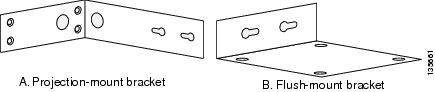
•![]() Metal projection-mount bracket (user orderable) for mounting the access point to a vertical wall (see Figure 2-6)
Metal projection-mount bracket (user orderable) for mounting the access point to a vertical wall (see Figure 2-6)
•![]() Metal flush-mount bracket (user orderable) for mounting the access point to a vertical wall (see Figure 2-6)
Metal flush-mount bracket (user orderable) for mounting the access point to a vertical wall (see Figure 2-6)
•![]() Ceiling-mount bezel kit (user orderable) for mounting the access point above a suspended ceiling tile. For additional information, refer to the Quick Start Guide: Ceiling Mount Bezels for Cisco Aironet 1000 Series Lightweight Access Points.
Ceiling-mount bezel kit (user orderable) for mounting the access point above a suspended ceiling tile. For additional information, refer to the Quick Start Guide: Ceiling Mount Bezels for Cisco Aironet 1000 Series Lightweight Access Points.
Figure 2-5 Factory-Supplied Mounting Options
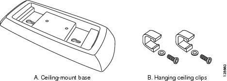
Figure 2-6 Orderable Mounting Brackets
Refer to the Table 2-1 to identify the materials you need to mount your access point, then go to the section containing the specific mounting procedure.
Mounting Access Points Using a Ceiling-Mount Base
When you are mounting the access point to horizontal surface, such as the ceiling of a building, use the ceiling-mount base to mount the access point. The ceiling-mount base can also be used to mount the access point to a desktop or shelf.
Figure 2-7 Attaching the Access Point and Ceiling-Mount Base
Follow these steps to attach the ceiling-mount base to the access point and mount the access point to a horizontal surface, such as a ceiling.
Step 1 ![]() Copy the MAC address(es) from the label(s) on the access point onto the corresponding location on your access point location map. MAC addresses have the format 00xxxxxxxxxx.
Copy the MAC address(es) from the label(s) on the access point onto the corresponding location on your access point location map. MAC addresses have the format 00xxxxxxxxxx.
Step 2 ![]() Find the required mounting location as identified on your access point location map.
Find the required mounting location as identified on your access point location map.
Step 3 ![]() Use the ceiling-mount base to mark the two screw key slots on the ceiling location. ensure to leave enough space around the access point and base to plug the CAT-5 cable, optional external antenna cable(s), optional power supply cable, and optional Kensington MicroSaver security cable into the sides of the access point.
Use the ceiling-mount base to mark the two screw key slots on the ceiling location. ensure to leave enough space around the access point and base to plug the CAT-5 cable, optional external antenna cable(s), optional power supply cable, and optional Kensington MicroSaver security cable into the sides of the access point.
Step 4 ![]() Install two screws in the marked key slots locations. Use appropriate screws and anchors (user supplied). Tighten the screws until the heads are about 1/8 inch from the ceiling surface.
Install two screws in the marked key slots locations. Use appropriate screws and anchors (user supplied). Tighten the screws until the heads are about 1/8 inch from the ceiling surface.
Step 5 ![]() Attach the ceiling-mount base to the bottom of the access point using the factory-supplied machine screws and washers (refer to Figure 2-7).
Attach the ceiling-mount base to the bottom of the access point using the factory-supplied machine screws and washers (refer to Figure 2-7).
Step 6 ![]() Position the access point with the ceiling-mount base so its keyhole slots are on over the screw heads and slide the ceiling-mount base in the direction of the key slots.
Position the access point with the ceiling-mount base so its keyhole slots are on over the screw heads and slide the ceiling-mount base in the direction of the key slots.
Note ![]() If the ceiling screws do not securely hold the access point, remove the ceiling-mount base and tighten the ceiling screws until they hold the access point securely.
If the ceiling screws do not securely hold the access point, remove the ceiling-mount base and tighten the ceiling screws until they hold the access point securely.
Step 7 ![]() Attach the cables to the access point.
Attach the cables to the access point.
Note ![]() When the access point is powered up and is associated with a controller (Power LED is green, Alarm LED is off, and the radio LEDs are blinking), the access point is broadcasting its beacon.
When the access point is powered up and is associated with a controller (Power LED is green, Alarm LED is off, and the radio LEDs are blinking), the access point is broadcasting its beacon.
Step 8 ![]() Repeat the these steps for each access point on a horizontal surface.
Repeat the these steps for each access point on a horizontal surface.
After mounting all horizontal surface access points, return to deploying the access points, "Step 3-c" on page 2-7.
Mounting Access Points Using the Ceiling-Mount Clips
When you are mounting the access point under a suspended ceiling, use the ceiling-mount clips to mount the access point to the suspended ceiling rails.
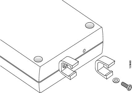
Figure 2-8 Attaching the Ceiling-Mount Clips to the Access Point
Follow these steps to attach the ceiling-mount clips to the access point and mount the access point to suspended ceiling rails:
Step 1 ![]() Copy the MAC address from the label on the access point onto the corresponding location on the access point location map. MAC addresses have the format 00xxxxxxxxxx.
Copy the MAC address from the label on the access point onto the corresponding location on the access point location map. MAC addresses have the format 00xxxxxxxxxx.
Step 2 ![]() Attach the ceiling-mount clips to the bottom of the access point using the factory-supplied machine screws and washers (see Figure 2-8).
Attach the ceiling-mount clips to the bottom of the access point using the factory-supplied machine screws and washers (see Figure 2-8).
Step 3 ![]() Snap the ceiling-mount clips onto a suspended ceiling rail (see Figure 9). Ensure you leave enough space around the access point to plug the Ethernet cable, optional external antenna cable(s), optional power supply cable, and optional Kensington MicroSaver security cable into the sides of the access point.
Snap the ceiling-mount clips onto a suspended ceiling rail (see Figure 9). Ensure you leave enough space around the access point to plug the Ethernet cable, optional external antenna cable(s), optional power supply cable, and optional Kensington MicroSaver security cable into the sides of the access point.
Figure 9 Mounting the Access Point with Ceiling-Mount Clips to a Suspended Ceiling Rail
Step 4 ![]() Attach the cables (Ethernet and optional antennas) to the sides of the access point.
Attach the cables (Ethernet and optional antennas) to the sides of the access point.
Note ![]() Ensure that the cables are routed away from the access point integrated antennas.
Ensure that the cables are routed away from the access point integrated antennas.
Note ![]() When the access point is powered up and is associated with a controller (Power LED is green, Alarm LED is off, and the radio LEDs are blinking), the access point radios are operational and broadcasting their beacons.
When the access point is powered up and is associated with a controller (Power LED is green, Alarm LED is off, and the radio LEDs are blinking), the access point radios are operational and broadcasting their beacons.
Step 5 ![]() Repeat Steps 1 to 4 for each suspended ceiling access point location.
Repeat Steps 1 to 4 for each suspended ceiling access point location.
After mounting all suspended ceiling access points, return to deploying the access points, "Step 3-c" on page 2-7.
Mounting the Access Point Using a Projection Wall Mount Bracket
When you are mounting the access point out from a vertical wall (flat sides along the wall or hallway), use an optional factory-orderable projection-mount L-bracket (see Figure 2-6). Follow these steps to attach the access point to the projection-mount bracket and mount the access point to a vertical wall:
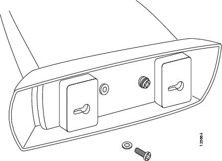
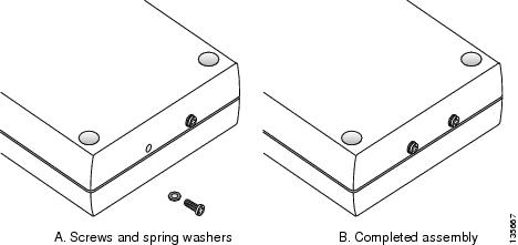
Step 1 ![]() Before proceeding, gently screw the two factory-supplied screws and spring washers into the bottom of the access point (see Figure 2-10). Ensure the spring washers have their convex (high center sections) pointing toward the screw heads.
Before proceeding, gently screw the two factory-supplied screws and spring washers into the bottom of the access point (see Figure 2-10). Ensure the spring washers have their convex (high center sections) pointing toward the screw heads.
Note ![]() Do not tighten the screw heads flush with the access point surface or the bracket will not fit under the screw heads.
Do not tighten the screw heads flush with the access point surface or the bracket will not fit under the screw heads.
Figure 2-10 Attaching the Mounting Screws to the Access Point
Step 2 ![]() Copy the MAC address(es) from the label(s) on the access point onto the corresponding location on the access point location map. MAC addresses have the format 00xxxxxxxxxx.
Copy the MAC address(es) from the label(s) on the access point onto the corresponding location on the access point location map. MAC addresses have the format 00xxxxxxxxxx.
Step 3 ![]() Find the required mounting location as identified on your access point location map.
Find the required mounting location as identified on your access point location map.
Step 4 ![]() Use the projection-mount bracket to mark the four screw holes on the wall. Ensure to leave enough space around the access point and base to plug the CAT-5 cable, optional external antenna cable(s), optional power supply cable, and optional Kensington MicroSaver security cable into the sides of the access point.
Use the projection-mount bracket to mark the four screw holes on the wall. Ensure to leave enough space around the access point and base to plug the CAT-5 cable, optional external antenna cable(s), optional power supply cable, and optional Kensington MicroSaver security cable into the sides of the access point.
Step 5 ![]() Mount the projection-bracket to the wall using four screws in the marked locations. Use appropriate screws and wall anchors (user supplied). Tighten the wall screws.
Mount the projection-bracket to the wall using four screws in the marked locations. Use appropriate screws and wall anchors (user supplied). Tighten the wall screws.
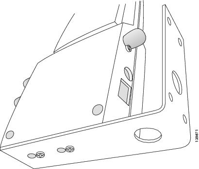
Step 6 ![]() Position the two screws in the base of the access point over the projection-bracket keyhole slots and slide the access point in the direction of the key slots (see Figure 2-11). If you are unable to attach the access point to the bracket, remove the access point and loosen the two access point screws.
Position the two screws in the base of the access point over the projection-bracket keyhole slots and slide the access point in the direction of the key slots (see Figure 2-11). If you are unable to attach the access point to the bracket, remove the access point and loosen the two access point screws.
Note ![]() After attaching the access point to the bracket, tighten the screws until they securely hold the access point.
After attaching the access point to the bracket, tighten the screws until they securely hold the access point.
Figure 2-11 Attaching the Access Point to the Projection-Mount Bracket
Step 7 ![]() Attach the cables to the sides of the access point. The Ethernet cable, optional external antenna cable(s), optional power supply cable, and optional Kensington MicroSaver security cables can be routed through the large holes in the mounting bracket.
Attach the cables to the sides of the access point. The Ethernet cable, optional external antenna cable(s), optional power supply cable, and optional Kensington MicroSaver security cables can be routed through the large holes in the mounting bracket.
Note ![]() Ensure that the cables are routed away from the access point integrated antennas.
Ensure that the cables are routed away from the access point integrated antennas.
Note ![]() When the access point is powered up and is associated with a controller (Power LED is green, 2.4 GHz LED is yellow, and 5.4 GHz LED is amber), the access point is broadcasting its beacon.
When the access point is powered up and is associated with a controller (Power LED is green, 2.4 GHz LED is yellow, and 5.4 GHz LED is amber), the access point is broadcasting its beacon.
Step 8 ![]() Repeat Steps 1 to 7 for each projection-mount bracket location.
Repeat Steps 1 to 7 for each projection-mount bracket location.
After mounting all your projection-mount access points, return to deploying the access points, "Step 3-c" on page 2-7.
Mounting the Access Point Using the Flush-Mount Bracket
When mounting the access point against a vertical wall (flat side toward the inside of the building), use an optional factory-orderable flush-mount bracket. Follow these steps to mount the bracket and attach the access point:
Step 1 ![]() Before proceeding, gently screw the two factory-supplied screws and spring washers into the bottom of the access point (see Figure 2-10). Ensure the spring washers have their convex (high center sections) pointing toward the screw heads.
Before proceeding, gently screw the two factory-supplied screws and spring washers into the bottom of the access point (see Figure 2-10). Ensure the spring washers have their convex (high center sections) pointing toward the screw heads.
Note ![]() Do not tighten the screw heads flush with the access point surface or the bracket will not fit under the screw heads.
Do not tighten the screw heads flush with the access point surface or the bracket will not fit under the screw heads.
Step 2 ![]() Copy the MAC address(es) from the label(s) on the access point onto the corresponding location on the access point location map. MAC addresses have the format 00xxxxxxxxxx.
Copy the MAC address(es) from the label(s) on the access point onto the corresponding location on the access point location map. MAC addresses have the format 00xxxxxxxxxx.
Step 3 ![]() Find the required mounting location as identified on your access point location map.
Find the required mounting location as identified on your access point location map.
Step 4 ![]() Use the flush-mount bracket to mark the four screw holes on the wall. Ensure to leave enough space around the access point and base to plug the CAT-5 cable, optional external antenna cable(s), optional power supply cable, and optional Kensington MicroSaver security cable into the sides of the access point.
Use the flush-mount bracket to mark the four screw holes on the wall. Ensure to leave enough space around the access point and base to plug the CAT-5 cable, optional external antenna cable(s), optional power supply cable, and optional Kensington MicroSaver security cable into the sides of the access point.
Step 5 ![]() Mount the flush-mount bracket to the wall using four screws in the marked locations. Use appropriate screws and wall anchors (user supplied). Tighten the wall screws.
Mount the flush-mount bracket to the wall using four screws in the marked locations. Use appropriate screws and wall anchors (user supplied). Tighten the wall screws.
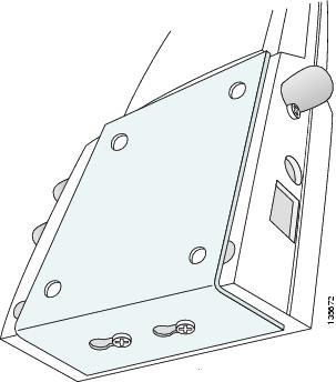
Step 6 ![]() Position the two screws in the base of the access point over the flush-mount bracket keyhole slots and slide the access point in the direction of the key slots (see Figure 2-12). If you are unable to attach the access point to the bracket, remove the access point and loosen the two access point screws.
Position the two screws in the base of the access point over the flush-mount bracket keyhole slots and slide the access point in the direction of the key slots (see Figure 2-12). If you are unable to attach the access point to the bracket, remove the access point and loosen the two access point screws.
Note ![]() Ensure the side of the access point with the door is facing away from the wall. This ensures that the correct antenna is facing the building, and makes future upgrades easier.
Ensure the side of the access point with the door is facing away from the wall. This ensures that the correct antenna is facing the building, and makes future upgrades easier.
Note ![]() After attaching the access point to the bracket, tighten the screws until they securely hold the access point.
After attaching the access point to the bracket, tighten the screws until they securely hold the access point.
Figure 2-12 Attaching the Access Point to the Flush-Mount Bracket
Step 7 ![]() Attach the cables to the sides of the access point (the Ethernet cable, optional external antenna cable(s), optional power supply cable, and optional Kensington MicroSaver security cable).
Attach the cables to the sides of the access point (the Ethernet cable, optional external antenna cable(s), optional power supply cable, and optional Kensington MicroSaver security cable).
Note ![]() Ensure that the cables are routed away from the access point integrated antennas.
Ensure that the cables are routed away from the access point integrated antennas.
Note ![]() When the access point is powered up and is associated with a controller (Power LED is green, Alarm LED is off, and the radio LEDs are blinking), the access point is broadcasting its beacon.
When the access point is powered up and is associated with a controller (Power LED is green, Alarm LED is off, and the radio LEDs are blinking), the access point is broadcasting its beacon.
Step 8 ![]() Repeat Steps 1 to 7 for each flush-mount bracket location.
Repeat Steps 1 to 7 for each flush-mount bracket location.
After mounting all your flush-mount access points, return to deploying the access points, "Step 3-c" on page 2-7.
Securing the Access Point Using a Security Cable
You can secure the access point by installing a standard security cable (such as the Kensington MicroSaver, model number 64068) into the access point security cable slot (see Figure 2-3). The security cable can be used with any of the mounting methods described in this guide provided the cable can be secured to a nearby immovable object.
Follow these steps to install the security cable.
Step 1 ![]() Loop the security cable around a nearby immovable object.
Loop the security cable around a nearby immovable object.
Step 2 ![]() Insert the key into the security cable lock.
Insert the key into the security cable lock.
Step 3 ![]() Insert the security cable latch into the security key slot on the access point.
Insert the security cable latch into the security key slot on the access point.
Step 4 ![]() Rotate the key right or left to secure the security cable lock to the access point.
Rotate the key right or left to secure the security cable lock to the access point.
Step 5 ![]() Remove the key from security cable lock.
Remove the key from security cable lock.
Step 6 ![]() Repeat Steps 1 to 4 for each access point requiring a security cable.
Repeat Steps 1 to 4 for each access point requiring a security cable.
After securing your access points, go to the "Connecting to an Ethernet Network with an Inline Power Source" section.
Connecting the Ethernet and Power Cables
The access point receives power through the Ethernet cable or an external power module.
Warning ![]() This product must be connected to a Power over Ethernet (PoE) IEEE 802.3af compliant power source or an IEC60950 compliant limited power source. Statement 353
This product must be connected to a Power over Ethernet (PoE) IEEE 802.3af compliant power source or an IEC60950 compliant limited power source. Statement 353
The access point power options:
•![]() Option 1—Switches with sufficient inline power:
Option 1—Switches with sufficient inline power:
–![]() An inline power capable switch, such as the Cisco Catalyst 3550 PWR XL, 3560-48PS, 3750-48PS, 4500 with 802.3AF PoE module, or the 6500 with 802.3AF PoE module
An inline power capable switch, such as the Cisco Catalyst 3550 PWR XL, 3560-48PS, 3750-48PS, 4500 with 802.3AF PoE module, or the 6500 with 802.3AF PoE module
–![]() Other inline power switches supporting the IEEE 802.3af inline power standard
Other inline power switches supporting the IEEE 802.3af inline power standard
•![]() Option 2—Switches without sufficient inline power can use the power injector:
Option 2—Switches without sufficient inline power can use the power injector:
–![]() Cisco Aironet Power Injector (AIR-PWRINJ-1000AF=)
Cisco Aironet Power Injector (AIR-PWRINJ-1000AF=)
•![]() Option 3—Local power using the power module (AIR-PWR-1000=)
Option 3—Local power using the power module (AIR-PWR-1000=)
Note ![]() Some older switches and patch panels might not provide enough power to operate the access point. At power-up, if the access point is unable to determine that the power source can supply sufficient power, the access point automatically deactivates both radios to prevent an over-current condition. All access LEDs are off.
Some older switches and patch panels might not provide enough power to operate the access point. At power-up, if the access point is unable to determine that the power source can supply sufficient power, the access point automatically deactivates both radios to prevent an over-current condition. All access LEDs are off.
Connecting to an Ethernet Network with an Inline Power Source
Note ![]() If your access point is connected to in-line power, do not connect the power module to the access point.
If your access point is connected to in-line power, do not connect the power module to the access point.
Follow these steps to connect the access point to the Ethernet LAN when you have an inline power source:
Step 1 ![]() Connect a Category 5 Ethernet cable to the RJ-45 Ethernet connector labeled Ethernet on the access point (see Figure 2-13).
Connect a Category 5 Ethernet cable to the RJ-45 Ethernet connector labeled Ethernet on the access point (see Figure 2-13).
Figure 2-13 Ethernet and Power Ports
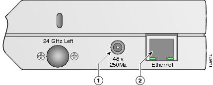
|
|
Ethernet port |
|
48 VDC power port |
Step 2 ![]() Connect the other end of the Ethernet cable to one of the following:
Connect the other end of the Ethernet cable to one of the following:
•![]() A switch with inline power (see the "Connecting the Ethernet and Power Cables" section).
A switch with inline power (see the "Connecting the Ethernet and Power Cables" section).
•![]() The Ethernet connector on the power injector (AIR-PWRINJ-1000AF) labeled J1 DATA & PWR. Also connect a Category 5 Ethernet cable from the power injector Ethernet connector labeled
The Ethernet connector on the power injector (AIR-PWRINJ-1000AF) labeled J1 DATA & PWR. Also connect a Category 5 Ethernet cable from the power injector Ethernet connector labeled
J2 DATA to a non-powered Ethernet port on your 10/100 Ethernet LAN.
Step 3 ![]() Repeat Steps 1 to 2 for each access point requiring in-line power.
Repeat Steps 1 to 2 for each access point requiring in-line power.
Connecting to an Ethernet Network with Local Power
Note ![]() If your access point is connected to in-line power, do not connect the power module to the access point.
If your access point is connected to in-line power, do not connect the power module to the access point.
Follow these steps to connect the access point to an Ethernet LAN when you are using a local power source:
Step 1 ![]() Connect a Category 5 Ethernet cable to the RJ-45 Ethernet connector labeled Ethernet on the access point (see Figure 2-13).
Connect a Category 5 Ethernet cable to the RJ-45 Ethernet connector labeled Ethernet on the access point (see Figure 2-13).
Step 2 ![]() Plug the other end of the Ethernet cable into an non-powered Ethernet port on your 10/100 Ethernet LAN.
Plug the other end of the Ethernet cable into an non-powered Ethernet port on your 10/100 Ethernet LAN.
Step 3 ![]() Connect the power module output connector to the access point's 48-VDC power port (see Figure 2-13).
Connect the power module output connector to the access point's 48-VDC power port (see Figure 2-13).
Step 4 ![]() Plug the power module power cord into an approved 100- to 240-VAC outlet.
Plug the power module power cord into an approved 100- to 240-VAC outlet.
Powering Up the Access Point
After you power up the access point, it begins a power-up sequence that you can check by observing the access point LEDs. The red Alarm LED turns on for about 15 to 20 seconds and then all LEDs blink sequentially back and forth, indicating that the access point is trying to find a controller. Refer to "Checking the Access Point LEDs" section for LED descriptions.
After the access point finds the controller, the access point downloads new operating system code if the access point code version differs from the controller code version. During the download process, all access point LEDs blink simultaneously. When the operating system download is successful, the access point reboots.
Normal operation is indicated when the Alarm LED is off, the Power LED is green, and the 2.4 GHz and 5 GHz LEDs are blinking to indicate radio activity.
If no LEDs are on, the access point might not be receiving sufficient power.
If all the LEDs blink sequentially for more than five minutes, the access point is unable to find its primary, secondary, or tertiary controllers. Check the connection between the access point and its controllers and ensure they are on the same subnet or that the access point has a route back to its primary, secondary, and tertiary controllers. If the access point is not on the same subnet as the controllers, ensure there is a properly configured DHCP server on the same subnet as the access point. See the "Using DHCP Option 43" section for DHCP information.
Note ![]() To allow client roaming between access points, the access points must be on the same subnet.
To allow client roaming between access points, the access points must be on the same subnet.
Note ![]() Connect only one power source to the access point, for example: When using in-line power, do not connect the power module to the access point.
Connect only one power source to the access point, for example: When using in-line power, do not connect the power module to the access point.
Returning MAC Information
When you have completed the access point deployment, return the access point MAC addresses and the access point locations on the access point location maps or floor plans to your network planner or manager. The network operators can use the MAC address and location information to create maps for precise wireless system management.
 Feedback