Overview
The Cisco Aironet 1000 Series Lightweight Access Points (hereafter called access points) combine mobility and flexibility with the enterprise-class features required by networking professionals. These access points are part of the Cisco Integrated Wireless Network Solution and require no manual configuration before they are mounted. The access point is automatically configured by a Cisco Wireless LAN Controller (hereafter called a controller) using the Lightweight Access Point Protocol (LWAPP).
The access point contains two integrated radios: a 2.4-GHz radio (IEEE 802.11g) and a 5-GHz radio (IEEE 802.11a). Using a controller, you can configure the radios separately with different settings on each.
In the Cisco Centralized Wireless LAN Architecture, access points operate in the lightweight mode (as opposed to autonomous mode). The access points associate to a controller. The controller manages the configuration, firmware, and control transactions such as 802.1x authentication. In addition, all wireless traffic is tunneled through the controller.
LWAPP is an Internet Engineering Task Force (IETF) draft protocol that defines the control messaging for setup and path authentication and run-time operations. LWAPP also defines the tunneling mechanism for data traffic.
In an LWAPP environment, a lightweight access point discovers a controller by using LWAPP discovery mechanisms and then sends it an LWAPP join request. The controller sends the access point an LWAPP join response allowing the access point to join the controller. When the access point is associated with a controller, it downloads new operating system software if the versions on the access point and controller do not match. After an access point is associated to a controller, you are able to reassign it to any controller on your network.
LWAPP secures the control communication between the access point and controller by means of a secure key distribution, utilizing X.509 certificates on both the access point and controller.
This chapter provides information on the following topics:
•![]() Guidelines for Using the Access Points
Guidelines for Using the Access Points
•![]() Network Configuration Example
Network Configuration Example
Guidelines for Using the Access Points
You should keep these guidelines in mind when you use the access points:
•![]() The access points can only communicate with controllers and can not operate independently.
The access points can only communicate with controllers and can not operate independently.
•![]() The access points communicate only with controllers and do not support Wireless Domain Services (WDS). The access points cannot communicate with WDS devices. However, the controller provides functionality equivalent to WDS when the access point associates to it.
The access points communicate only with controllers and do not support Wireless Domain Services (WDS). The access points cannot communicate with WDS devices. However, the controller provides functionality equivalent to WDS when the access point associates to it.
•![]() The access points support Layer 2 or Layer 3 LWAPP communications with the controllers. In
The access points support Layer 2 or Layer 3 LWAPP communications with the controllers. In
Layer 2 operation, the access point and the controller must be on the same subnet and communicate with each other using MAC addresses in encapsulated Ethernet frames. This operation is not scalable to larger networks and not recommended by Cisco.
In Layer 3 operation, the access point and the controller can be on the same or different subnets. The access point communicates with the controller using standard IP packets. Layer 3 operation is scalable and is recommended by Cisco. A Layer 3 access point on a different subnet than the controller requires a DHCP server on the access point subnet and a route to the controller. The route to the controller must have destination UDP ports 12222 and 12223 open for LWAPP communications. The route to the primary, secondary, and tertiary controllers must allow IP packet fragments.
•![]() Before deploying your access points ensure the following has been done:
Before deploying your access points ensure the following has been done:
–![]() Your controllers are connected to switch ports that are configured as trunk ports.
Your controllers are connected to switch ports that are configured as trunk ports.
–![]() Your access points are connected to switch ports that are configured as untagged access ports
Your access points are connected to switch ports that are configured as untagged access ports
–![]() A DHCP server is reachable by your access points and has been configured with Option 43. Option 43 is used to provide the IP addresses of the Management Interfaces of your controllers. Typically, a DHCP server can be configured on a Cisco switch.
A DHCP server is reachable by your access points and has been configured with Option 43. Option 43 is used to provide the IP addresses of the Management Interfaces of your controllers. Typically, a DHCP server can be configured on a Cisco switch.
–![]() Optionally a DNS server can be configured to enable "CISCO-LWAPP-CONTROLLER.<local domain>" to resolve to the IP address of the Management Interface of your controller.
Optionally a DNS server can be configured to enable "CISCO-LWAPP-CONTROLLER.<local domain>" to resolve to the IP address of the Management Interface of your controller.
–![]() Your controllers are configured and reachable by the access points.
Your controllers are configured and reachable by the access points.
Hardware Features
Key hardware features of the access point include:
•![]() Single or dual-radio operation (see page 4)
Single or dual-radio operation (see page 4)
•![]() Ethernet port (see page 5)
Ethernet port (see page 5)
•![]() LEDs, (see page 5)
LEDs, (see page 5)
•![]() Multiple power sources (see page 5)
Multiple power sources (see page 5)
•![]() Anti-theft features (see page 6)
Anti-theft features (see page 6)
•![]() UL 2043 certification (see page 6)
UL 2043 certification (see page 6)
Refer to "Access Point Specifications," for a list of access point specifications.
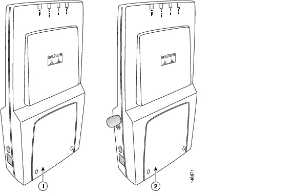
Figure 1-2 shows the access point.
Figure 1-1 Access Point Configurations
|
|
Integrated antennas only (AIR-AP1010) |
|
Integrated antennas and external antenna connectors (AIR-AP1020 and AIR-AP1030) |
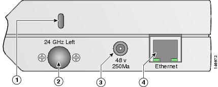
Figure 1-2 illustrates the left side connectors on the access point.
Figure 1-2 Access Point Left Side Connectors
|
|
Security key slot |
|
48-VDC power port |
|
|
2.4-GHz antenna connector (left) |
|
Ethernet port (RJ-45) |
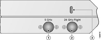
Figure 1-3 illustrates the right side connectors on the access point.
Figure 1-3 Access Point Right Side Connectors
|
|
5-GHz antenna connector (right) |
|
2.4-GHz antenna connector (right) |
|
|
Security key slot |
||
Single or Dual-Radio Operation
The access point supports single or simultaneous dual radio operation using a 2.4-GHz 802.11g radio and a 5-GHz 802.11a radio. The radios use integrated sector patch antennas or external antennas (see the "Antennas Supported" section).
The 5-GHz radio incorporates an Unlicensed National Information Infrastructure (UNII) radio transceiver operating in the UNII 5-GHz frequency bands.
Antennas Supported
The access points are available in three configurations:
•![]() AIR-AP1010—Supports only integrated antennas
AIR-AP1010—Supports only integrated antennas
•![]() AIR-AP1020—Supports integrated and external antennas
AIR-AP1020—Supports integrated and external antennas
•![]() AIR-AP1030—Supports integrated and external antennas
AIR-AP1030—Supports integrated and external antennas
The 2.4 GHz and 5 GHz radios have two integrated 6 dBi directional patch antennas. The integrated antennas provide diversity operation for the 2.4 GHz radio. The antennas are located on the front and back sides of the access point.

Table 1-1 lists the supported external antennas.
Ethernet Port
The auto-sensing Ethernet port accepts an RJ-45 connector, linking the access point to your 10BASE-T or 100BASE-T Ethernet LAN (see Figure 1-2). The access point can receive power through the Ethernet cable from a power injector, switch, or power patch panel. The Ethernet MAC address is printed on the label on the side of the access point (refer to the "Finding the Product Serial Number" section).
LEDs
The access point has four LEDs to provide a visual indication of access point operations (refer to the "Checking the Access Point LEDs" section for additional information).
•![]() Power LED
Power LED
•![]() Alarm LED
Alarm LED
•![]() 2.4 GHz LED
2.4 GHz LED
•![]() 5 GHz LED
5 GHz LED
Power Sources
The access point can receive power from an external power module or from inline power using the Ethernet cable. The access point supports the IEEE 802.3af inline power standard. Using inline power, you do not need to run a power cord to the access point because power is supplied over the Ethernet cable.

Warning ![]() This product must be connected to a Power over Ethernet (PoE) IEEE 802.3af compliant power source or an IEC60950 compliant limited power source. Statement 353
This product must be connected to a Power over Ethernet (PoE) IEEE 802.3af compliant power source or an IEC60950 compliant limited power source. Statement 353
The access point supports the following power sources:
•![]() Power module (AIR-PWR-1000=)
Power module (AIR-PWR-1000=)
•![]() Inline power:
Inline power:
–![]() Cisco Aironet 1000 series access point power injector (AIR-PWRINJ-1000AF=)
Cisco Aironet 1000 series access point power injector (AIR-PWRINJ-1000AF=)
–![]() An inline power capable switch, such as the Cisco Catalyst 3550 PWR XL, 3560-48PS, 3570-48PS, 4500 with 802.3AF PoE module, or the 6500 with 802.3AF PoE module
An inline power capable switch, such as the Cisco Catalyst 3550 PWR XL, 3560-48PS, 3570-48PS, 4500 with 802.3AF PoE module, or the 6500 with 802.3AF PoE module
–![]() Other inline power switches supporting the IEEE 802.3af inline power standard
Other inline power switches supporting the IEEE 802.3af inline power standard

Note ![]() The access point requires 12 W of inline power. Some switches and patch panels might not provide enough power to operate the access point. If the access point is unable to determine that the power source can supply sufficient power, the access point does not activate the radios and does not turn on the Power LED.
The access point requires 12 W of inline power. Some switches and patch panels might not provide enough power to operate the access point. If the access point is unable to determine that the power source can supply sufficient power, the access point does not activate the radios and does not turn on the Power LED.
UL 2043 Certification
The access point has adequate fire resistance and low smoke-producing characteristics suitable for operation in a building's environmental air space, such as above suspended ceilings, in accordance with Section 300-22(c) of the NEC, and with Sections 2-128, 12-010(3) and 12-100 of the Canadian Electrical Code, Part 1, C22.1.
Anti-Theft Features
The access point supports two security cable keyholes (see Figure 1-2 and Figure 1-3) to secure the access point using a standard security cable, like those used on laptop computers.
Network Configuration Example
The access points support Layer 2 or Layer 3 network operation. In Layer 2 configurations, the access point and the controller are on the same subnet and communicate with encapsulated Ethernet frames using MAC addresses rather than IP addresses. Layer 2 configurations are typically not scalable into larger networks. Additionally, Layer 2 operation is supported only by the Cisco 4400 series controllers.
Access points and controllers in Layer 3 configurations use IP addresses and UDP packets, which can be routed through large networks. Layer 3 operation is scalable and recommended by Cisco.
Figure 1-4 illustrates a typical Layer 3 wireless network configuration containing access points and a controller.
Figure 1-4 Typical Layer 3 Access Point Network Configuration Example
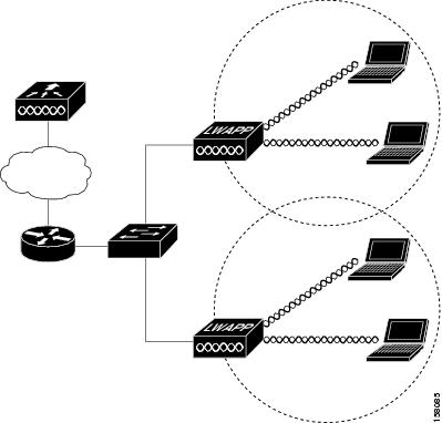
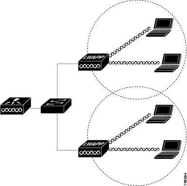
Figure 1-5 illustrates a typical Layer 2 network configuration. In a Layer 2 configuration, the controller and the access points are on the same subnet.
Figure 1-5 Typical Layer 2 Access Point Network Configuration Example
 Feedback