- End-to-End Planning Guide Change History
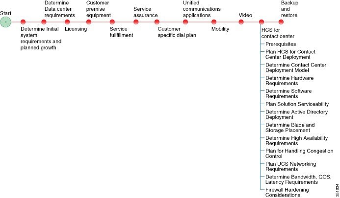
- End-to-End Planning Overview
- Initial System Requirements Planned Growth
- Data Center
- License Planning
- Customer Premise Equipment
- Service Fulfillment Planning
- Service Assurance
- Customer Specific Dial Plan
- Unified Communications Application Planning
- Mobility
- Video
- HCS for Contact Center
- Backup and Restore
- Prerequisites
- HCS for Contact Center Workflow
- Plan the HCS for Contact Center Deployment
- Determine the HCS for Contact Center Deployment Model
- Configuration Limits
- Features & Options in Small Contact Center Deployment
- Optional Component Considerations
- Optional Component Bandwidth, Latency and QOS Considerations
HCS for Contact Center
Prerequisites
Before you plan the HCS for Contact Center deployment, review the Cisco Hosted Collaboration Solution, Release 10.6(1) Solution Reference Network Design Guide and Installing and Configuring Cisco HCS for Contact Center.
HCS for Contact Center Workflow
|
Plan the HCS for Contact Center Deployment
The following sections provide HCS for Contact Center deployment planning details:
- Determine the HCS for Contact Center Deployment Model
- Determine the Hardware Requirements
- Determine the Software Requirements
- Plan Solution Serviceability
- Determine the Active Directory Deployment
- Determine the Blade and Storage Placement Requirements
- Determine High Availability Requirements
- Plan the Solution for Handling Congestion Control
- Plan the UCS Networking Requirements
- Determine the Trunk Design
- Firewall Hardening Considerations
Determine the HCS for Contact Center Deployment Model
| Step 1 | Identify the number of agents that you require: 100 or less, 500, 1000, 4000 or 12,000. |
| Step 2 | Review the Configuration Limits for agents, supervisors, teams, and reporting users of each deployment model. Consider your initial requirements as well as any planned growth. |
| Step 3 | Identify any
optional Cisco components to include in the deployment.
|
| Step 4 | Review the Optional Component Considerations. Consider your initial requirements as well as any planned growth. |
| Step 5 | Identify any third-party components to include in the deployment. |
Configuration Limits
| Group | Resource | 500 Agent Deployment | 1000 Agent Deployment | 4000 Agent Deployment |
12000 Agent Deployment |
Small Contact Center Deployment |
|---|---|---|---|---|---|---|
| Agents |
Active Agents* |
500 | 1000 | 4000 | 12000 | 4000 |
|
Configured Agents* |
3000 | 6000 | 24000 | 72000 | 24000 | |
|
Agents with Trace ON |
50* | 100* | 400* | 400 | 400* | |
|
Agent Desk Settings* |
500 | 1000 | 4000 | 12000 | 4000 | |
|
Active Mobile Agents |
125 | 250 |
See, Mobile Agent Support |
See, Mobile Agent Support |
See, Mobile Agent Support |
|
|
Configured Mobile Agents |
750 | 1500 | 6000 | 8000 | 6000 | |
|
Outbound Agents |
500 | 1000 | 4000 | 12000 | 4000 | |
|
Agents per team |
50* | 50* | 50* | 50 | 50* | |
|
Queues per Agent (Skill Groups and Precision Queues combined) |
15* | 15* | 15* | 15 | 15* | |
|
Agents per skill group |
No limit |
No limit |
No limit |
No limit |
No limit |
|
|
Attributes per agent* |
50 | 50 | 50 | 50 | 50 | |
| Supervisors |
Active Supervisors* |
50 | 100 | 400 | 1200 | 400 |
|
Configured Supervisors* |
300 | 600 | 2400 | 7200 | 2400 | |
|
Active teams* |
50 | 100 | 400 | 1200 | 400 | |
|
Configured teams* |
300 | 600 | 2400 | 7200 | 2400 | |
|
Supervisors per Team |
10* | 10* | 10* | 10 | 10* | |
|
Teams per supervisor |
20* | 20* | 20* | 20 | 20* | |
|
Agents per supervisor |
20 | 20 | 20 | 20 | 20 | |
| Reporting |
Active Reporting users |
50 | 100 | 400 | 1200 | 400 |
|
Configured Reporting users |
300 | 600 | 2400 | 7200 | 2400 | |
| Access Control | Administrator (Users) | 100 | 100 | 1000 | 1000 | 1000 |
Mobile Agent Support
Follow the below calculation to determine mobile agent capacity:
Each mobile agent for a nailed connection (nailed-up configuration) = two local agents
| Group | Resource | 500 Agent Deployment | 1000 Agent Deployment | 4000 Agent Deployment | 12000 Agent Deployment | Small Contact Center Deployment |
|---|---|---|---|---|---|---|
| Outbound | Dialer per system | 1 | 1 | 2 | 6 | 32 |
| Number of Campaigns (Agent/IVR based) | 50 | 300 | 300 | 300 | 300 | |
| Campaign skill groups per campaign | 20 | 20 | 20 | 20 | 20 | |
|
Queues per Agent (Skill Groups and Precision Queues combined) |
15 | 15 | 15 | 15 | 15 | |
| Total Numbers of Agents | 500 | 1000 | 4000 | 12000 | 4000 | |
| Port Throttle | 5 | 10 | 10 | 15 | 10 | |
| Group | Resource | 500 Agent Deployment | 1000 Agent Deployment | 4000 Agent Deployment | 12000 Agent Deployment | Small Contact Center Deployment |
| Precision Queues | Precision Queues* | 4000 | 4000 | 4000 | 4000 | 4000 |
| Precision Queue steps* | 10000 | 10000 | 10000 | 10000 | 10000 | |
| Precision Queue term per Precision Queue* | 10 | 10 | 10 | 10 | 10 | |
| Precision steps per Precision Queue* | 10 | 10 | 10 | 10 | 10 | |
| Unique attributes per Precision Queue* | 10 | 10 | 10 | 10 | 10 | |
| General | Attributes* | 10000 | 10000 | 10000 | 10000 | 10000 |
| Bucket Intervals | 500 | 1000 | 4000 | 12000 | 4000 | |
| Active Call Types | 1000 | 2000 | 8000 | 8000 | 8000 | |
| Configured Call Types* | 2000 | 2000 | 10000 | 10000 | 10000 | |
| Call Type Skill Group per Interval | 2000 | 2000 | 30000 | 30000 | 30000 | |
| Active Routing Scripts | 250 | 500 | 2000 | 6000 | 2000 | |
| Configured Routing Scripts | 500 | 1000 | 4000 | 12000 | 4000 | |
| Network VRU Scripts * | 500 | 1000 | 4000 | 12000 | 4000 | |
| Reason Codes | 100 | 100 | 100 | 100 | 100 | |
| Skill Groups* | 3000 | 3000 | 3000 | 3000 | 3000 | |
| Persistent Enabled Expanded Call Variables * | 20 | 20 | 5 | 5 | 5 | |
| Persistent Enabled Expanded Call Variable Arrays | 0 | 0 | 0 | 0 | 0 | |
| Nonpersistent Expanded Call Variables(Bytes)* | 2000 | 2000 | 2000 | 2000 | 2000 | |
| Bulk Jobs | 200 | 200 | 200 | 200 | 200 | |
| CTI All event Clients | 9/PG | 9/PG | 9/PG | 9/PG | 9/PG | |
| Group | Resource | 500 Agent Deployment | 1000 Agent Deployment | 4000 Agent Deployment | 12000 Agent Deployment | Small Contact Center Deployment |
| Dialed Number | Dialed Number (External Voice) | 1000 | 1000 | 4000 | 12000 | 4000 |
| Dialed Number (Internal Voice) | 1000 | 1000 | 4000 | 12000 | 4000 | |
| Dialed Number (Multichannel) | 500 | 500 | 2000 | 6000 | 2000 | |
| Dialed Number (Outbound Voice) | 500 | 500 | 2000 | 6000 | 2000 | |
| Load | VRU Ports | 900 | 1800 | 7200 | 21600 | 7200 |
| Calls per second | 5 | 8 | 35 | 115 | 35 | |
| Agent Load | 30 BHCA | 30 BHCA | 30 BHCA | 30 BHCA | 30 BHCA | |
| Reskilling | Dynamic (operations/hr.) | 120 | 120 | 120 | 120 | 120 |
Features & Options in Small Contact Center Deployment
| Features/Optional Components | Notes |
|---|---|
| Outbound Dialer | A single Outbound Dialer per Sub customer is supported, not exceeding 32 sub customers. |
| Outbound Campaigns | Each sub-customer supports 30 campaigns and total campaigns supported is 300. |
| WIM and EIM | A single WIM and EIM instance per sub customer is supported, not exceeding 74 sub customers. |
| Remote Silent Monitoring |
A single RSM instance will support up to 6 sub customers and 120 concurrent sessions supported per RSM. A single RSM instance per sub customer is supported. |
| Media Sense | A single Media Sense instance per sub customer, not exceeding 149 sub customers. |
Optional Component Considerations
- Unified WIM and EIM Considerations
- Cisco RSM Capabilities
- Cisco MediaSense Capabilities
- Optional Component Considerations
- Optional Component Bandwidth, Latency and QOS Considerations
Unified WIM and EIM Considerations
This section describes the following considerations for Unified WIM and EIM.
- Unified WIM and EIM Deployment Options
- Unified WIM and EIM Configuration Limits
- HCS Support Matrix for Unified WIM and EIM
Unified WIM and EIM Deployment Options
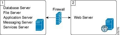
Collocated Deployment
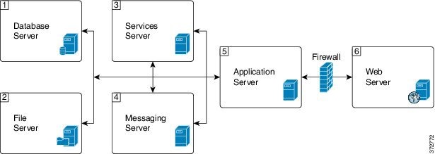
Due to the modular, component-based nature of the architecture, Cisco WIM and EIM has the ability to cater to the growing demands for concurrent user loads. To provide the flexibility to suit deployments of varied sizes, Cisco WIM and EIM supports various components that may be distributed across various servers in a deployment.
In Collocated deployment option, the web server is installed on a separate machine and all other components are installed on one machine. The web server may be installed outside the firewall, if required.
Unified WIM and EIM Configuration Limits
Unified WIM and EIM Configuration Limits
| Group | Resource | Unified WIM and EIM Distributed server Deployment | Unified WIM and EIM Collocated Deployment |
|---|---|---|---|
| Multimedia |
Agents (any combination of Email, Chat and Web callback activities) |
1250 # | 200 ## |
|
Maximum Number of Emails per agent per hour |
5 | 12 | |
|
Maximum Number of chats per agent per hour |
5 | 10 | |
|
Maximum Number of Web Callback per agents per hour |
5 | 5 |
 Note | The Symbol "#" indicates that the Unified WIM and EIM Distributed server Deployment allows combination of maximum 600 concurrent Web Callback and for the remaining it allows any combination of Email or Chat activities. The Symbol "##" indicates that the Unified WIM and EIM Collocated Deployment allows combination of maximum 100 concurrent Web Callback and for the remaining it allows any combination of Email or Chat activities. |
HCS Support Matrix for Unified WIM and EIM
HCS Support Matrix for Unified WIM and EIM
| HCS for CC Deployment | Unified WIM and EIM Distributed server Deployment | Unified WIM and EIM Collocated Deployment |
|---|---|---|
| HCS for CC 500 Agent Deployment | Support can't exceed 500 Multimedia agents | Yes |
| HCS for CC 1000 Agent Deployment | Support can't exceed 1000 Multimedia agents | Yes |
| HCS for CC 4000 Agent Deployment | Yes | Yes |
| HCS for CC 12000 Agent Deployment | Yes | Yes |
| HCS for CC Small Contact Center Agent Deployment | No | Yes |
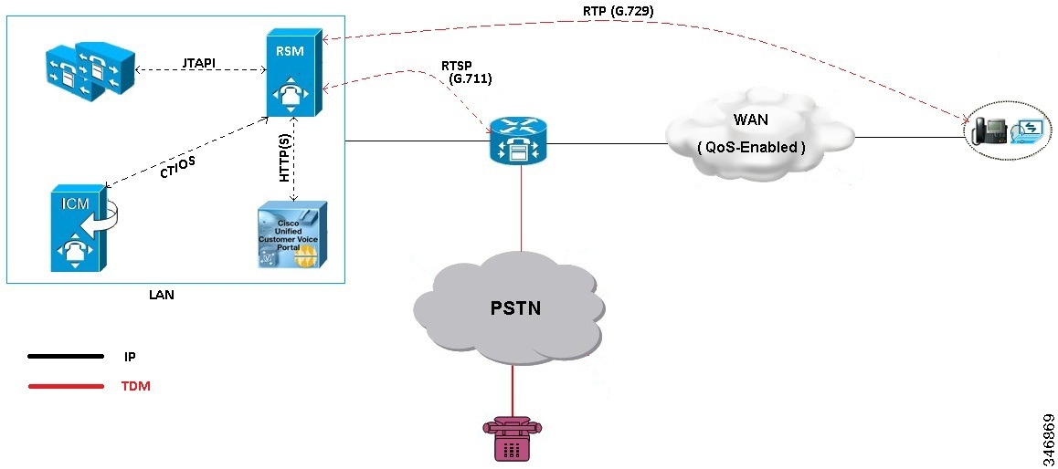
Cisco RSM Capabilities
| Platform | Capabilities |
|---|---|
|
Call Flow |
The Supervisor can only monitor agents who are in talking state. |
|
Desktop |
CTIOS |
|
Voice Codec |
Between Agent and RSM: G.729 (RTP) Between RSM and VXML Gateway: G.711 (RTSP) |
|
Concurrent Monitoring Sessions |
120 |
|
Monitored Calls (per minute) |
17 |
|
Maximum Configured Agents per PG |
12000 |
|
SimPhone Start line Number Range |
Four to fifteen digits |
Cisco MediaSense Capabilities
| Platform | Capabilities |
|---|---|
| Phone | All HCS supported Phone. See list of supported phones in Voice Infrastructure section. |
| Supported Model | 2vCPU, 4vCPU and 7vCPU profiles. |
| Voice Codec | G.711 and G.729 |
| Session |
See session related details in http://docwiki.cisco.com/wiki/Virtualization_for_Cisco_MediaSense#Version_10.x. |
| Media Forking | CUBE, Phone and TDM |
| Network | Inter cluster communication over WAN is not supported. |
Voice Infrastructure
|
Voice Infrastructure |
HCS for Contact Center Deployment |
Notes |
|---|---|---|
|
Music on Hold |
Unicast Multicast Unified CM Subscriber source only |
This sizing applies to agent node only, for both agent and back-office devices, with all agent devices on the same node pair. |
|
Proxy |
SIP Proxy is optionally supported. |
High Availability (HA) and load balancing are achieved using these solution components: |
|
Ingress Gateways |
ISR G2 Cisco Unified Border Element with combination VXML |
3925E and 3945E are the supported GWs. For SPAN based Silent Monitoring, the Ingress gateway is spanned. You must configure the gateway MTPs to do a codec pass-through because the Mobile Agent in HCS is configured to use G729 and the rest of the components in HCS support all the codecs. See CVP SRND for list of supported gateway models and corresponding sizing. |
|
Protocol |
Session Initiation Protocol (SIP) over TCP |
SIP over UDP, H323, Media Gateway Control Protocol (MGCP) are not supported. |
|
Proxy /Cisco Unified SIP Proxy (CUSP) |
SIP Proxy is optionally supported. |
Outbound Option: The Outbound dialer can connect to only one physical gateway, if SIP proxy is not used. See Configuration Limits |
|
Codec |
G.722, iSAC, and iLBC are not supported. |
|
|
Media Resources |
Gateway-based: |
Unified CM-based (Cisco IP Voice Media Streaming Application) that are not supported: |
Optional Component Considerations
- Unified WIM and EIM Considerations
- Cisco RSM Considerations
- Cisco MediaSense Considerations
- Cisco Unified SIP Proxy Considerations
- Cisco SPAN based Monitoring Considerations
Unified WIM and EIM Considerations
This section describes the following considerations for Unified WIM and EIM.
- Unified WIM and EIM Design Considerations
- Unified WIM and EIM Deployment Options
- Unified WIM and EIM Configuration Limits
- HCS Support Matrix for Unified WIM and EIM
- Unified WIM and WIM High Availability
- Cisco WIM and EIM Bandwidth, Latency and QOS Considerations
Unified WIM and EIM Design Considerations
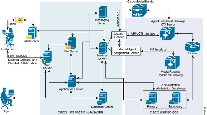
Note | Cisco Media Blender is used only for Web/Scheduled Callback feature. |
Unified WIM and EIM Deployment Options
Collocated Deployment
Due to the modular, component-based nature of the architecture, Cisco WIM and EIM has the ability to cater to the growing demands for concurrent user loads. To provide the flexibility to suit deployments of varied sizes, Cisco WIM and EIM supports various components that may be distributed across various servers in a deployment.
In Collocated deployment option, the web server is installed on a separate machine and all other components are installed on one machine. The web server may be installed outside the firewall, if required.
Unified WIM and EIM Configuration Limits
Unified WIM and EIM Configuration Limits
| Group | Resource | Unified WIM and EIM Distributed server Deployment | Unified WIM and EIM Collocated Deployment |
|---|---|---|---|
| Multimedia |
Agents (any combination of Email, Chat and Web callback activities) |
1250 # | 200 ## |
|
Maximum Number of Emails per agent per hour |
5 | 12 | |
|
Maximum Number of chats per agent per hour |
5 | 10 | |
|
Maximum Number of Web Callback per agents per hour |
5 | 5 |
Note | The Symbol "#" indicates that the Unified WIM and EIM Distributed server Deployment allows combination of maximum 600 concurrent Web Callback and for the remaining it allows any combination of Email or Chat activities. The Symbol "##" indicates that the Unified WIM and EIM Collocated Deployment allows combination of maximum 100 concurrent Web Callback and for the remaining it allows any combination of Email or Chat activities. |
HCS Support Matrix for Unified WIM and EIM
HCS Support Matrix for Unified WIM and EIM
| HCS for CC Deployment | Unified WIM and EIM Distributed server Deployment | Unified WIM and EIM Collocated Deployment |
|---|---|---|
| HCS for CC 500 Agent Deployment | Support can't exceed 500 Multimedia agents | Yes |
| HCS for CC 1000 Agent Deployment | Support can't exceed 1000 Multimedia agents | Yes |
| HCS for CC 4000 Agent Deployment | Yes | Yes |
| HCS for CC 12000 Agent Deployment | Yes | Yes |
| HCS for CC Small Contact Center Agent Deployment | No | Yes |
Unified WIM and WIM High Availability
The following table contains the Cisco Unified WIM and EIMhigh availability during the failover of Unified CCE processes.
| Component | Failover scenario | New session (Web Callback/ Delayed callback/ Chat/ Email) impact | Active session (Web Callback/ Delayed callback/ Chat/ Email) impact | Post recovery action |
|---|---|---|---|---|
| PG | Unified Communications Manager PG Failover | Web Callback - The new call is lost, because there is no Longest Available agent during the failure of PG. Delayed Callback - The new call reaches the customer and the agent after the PG on the other side becomes active and the delay that the customer specifies gets complete. Chat - The new chat initiated by the customer reaches the agent after the other side of the PG becomes active. Email - The new Email sent by the customer reaches the agent. |
Active Web Callback, Delayed callback, Chat, and Email sessions continue uninterrupted. | Agent receives the Call, Chat or Email after the PG becomes active and the agent logins again. |
| PG | MR PG Failover | Web Callback - The new call is established between the customer and the agent after the PG becomes active. Delayed Callback - The new call reaches the customer and the agent after the PG on the other side becomes active and the delay that the customer specifies gets complete. Chat - The new chat initiated by the customer reaches the agent once the other side of the PG becomes active. Email - The new Email sent by the customer reaches the agent. |
Active Web Callback, Delayed callback, Chat, and Email sessions continue uninterrupted. | Agent receives the Call, Chat or Email once the PG becomes active. |
| CG | CTI Failover | Web Callback -The new call cannot be placed and the customer receives the message, "System cannot assign an Agent to the request." Delayed Callback - The new call reaches the customer and the agent after the CG on the other side becomes active and the delay that the customer specifies gets complete. Chat - The new chat initiated by the customer reaches the agent after the other side of the CG process becomes active. Email - The new Email sent by the customer reaches the agent. |
Active Web Callback, Delayed callback, Chat, and Email sessions continue uninterrupted. | Agent receives the Call, Chat or Email once the process becomes active. |
| CTI OS | CTI OS Server Failure | Web Callback - The new call is established without any impact. Delayed Callback - The new call is established without any impact after the delay that the customer specifies gets complete. Chat - The new chat reaches the agent without any impact. Email - The new Email sent by the customer reaches the agent. |
Active Web Callback, Delayed callback, Chat, and Email sessions continue uninterrupted. | Seamless. |
| Router | Router fails | Web Callback - The new call is established through other side of the router process. Delayed Callback - The new call is established through other side of the router process and once the delay mentioned by the customer completes. Chat - The new chat reaches the agent through other side of the router process. Email - The new Email sent by the customer reaches the agent through other side of the router process. |
Active Web Callback, Delayed callback, Chat and Email sessions continue uninterrupted. | Agent gets the Call, Chat or Email with other side of the router process. |
Cisco WIM and EIM Bandwidth, Latency and QOS Considerations
The minimum required network bandwidth for an agent connecting to the Cisco Interaction Manager servers on login is 384 kilobits/second or greater. After login in a steady state an average bandwidth of 40 kilobits/second or greater is required.
An attachment of size up to 50 KB is supported within this required bandwidth. For attachments of size greater than 50 KB, you may experience slow speed temporarily in the agent user interface during download of the attachments.
Cisco RSM Considerations
- Cisco RSM Design Considerations
- Cisco RSM High Availability
- Cisco RSM Capabilities
- Cisco RSM Bandwidth, Latency and QOS Considerations
Cisco RSM Design Considerations
Cisco RSM High Availability
| Component | Failover/Failure Scenario | New Call Impact | Active Call Impact | Post-recovery Action |
|---|---|---|---|---|
| RSM Server | RSM server (hardware) fails | Attempts to contact the RSM server fail | Active monitoring sessions terminate and supervisor is directed to the main menu | Supervisor can monitor calls after the RSM server becomes active |
| CTI OS Server | CTI OS Server Failure | Supervisor can monitor new calls without any failure | Active monitoring sessions will continue normally | Failover is seamless |
| CTI | Active CTI Gateway process fails | Supervisor can establish new monitoring sessions until the secondary CTI process becomes active | Active monitoring sessions continue normally | After the CTI Gateway becomes active the supervisor can establish new monitoring sessions |
| VLEngine | VLEngine fails | Supervisor can establish new monitoring sessions when VLEngine becomes active | Active monitoring sessions terminate and supervisor is directed to the main menu | After the VLEngine becomes active the supervisor can establish new monitoring sessions |
| PhoneSim | PhoneSim fails | Supervisor can monitor new calls when PhoneSim becomes active | Active monitoring sessions continue normally | After the PhoneSim becomes active the supervisor can establish new monitoring sessions |
| Unified CM | Active Subscriber fails | New calls cannot be established until the secondary subscriber becomes active | Active monitoring sessions continue normally | After the secondary subscriber becomes active the supervisor can establish new monitoring sessions |
| JTAPI | JTAPI gateway fails | Supervisor can establish new calls without any failure | Active monitoring sessions continue normally | Failover is seamless |
| Unified CVP | Active CVP fails | New calls cannot be established until the Unified CVP becomes active | Active monitoring sessions terminate | After the Unified CVP becomes active the supervisor can establish new monitoring sessions |
Cisco RSM Capabilities
| Platform | Capabilities |
|---|---|
|
Call Flow |
The Supervisor can only monitor agents who are in talking state. |
|
Desktop |
CTIOS |
|
Voice Codec |
Between Agent and RSM: G.729 (RTP) Between RSM and VXML Gateway: G.711 (RTSP) |
|
Concurrent Monitoring Sessions |
120 |
|
Monitored Calls (per minute) |
17 |
|
Maximum Configured Agents per PG |
12000 |
|
SimPhone Start line Number Range |
Four to fifteen digits |
Cisco RSM Bandwidth, Latency and QOS Considerations
| RSM Peer | Purpose | Protocols Used | Data Format | Relative Bandwidth Requirements | Link Latency Requirements |
|---|---|---|---|---|---|
| VRU | Service Requests and Responses | TCP (HTTP) | Textual | Minimal | < 500 ms avg. |
| VRU | Requested Voice Data from PhoneSim to VRU | TCP (HTTP) | G711, chunked transfer mode encoding | High (about 67 to 87 kbps per session) | < 400 ms avg. |
| Unified CM | Issuance of Agent Phone Monitoring | TCP (JTAPI) | Binary (JTAPI stream) | Minimal | < 300 ms avg. |
| CTI OS Server (PG) | Environment Events and Supervisor Logins | TCP (CTI OS) | Binary (CTI OS stream) | Minimal | < 300 ms avg. |
| Agent Phones | Simulated Phone Signaling | TCP or UDP (SIP) | Textual | Minimal | < 400 ms avg. |
| Agent Phones | Monitored Phone Voice Data | UDP (RTP) | Binary (G.711) | High (about 67 to 87 kbps per session) | < 400 ms avg |
Cisco MediaSense Considerations
- Cisco MediaSense Design Considerations
- Cisco MediaSense Capabilities
- Cisco MediaSense High Availability
- Cisco MediaSense Bandwidth, Latency and QOS Considerations
Cisco MediaSense Design Considerations
Cisco MediaSense Capabilities
| Platform | Capabilities |
|---|---|
| Phone | All HCS supported Phone. See list of supported phones in Voice Infrastructure section. |
| Supported Model | 2vCPU, 4vCPU and 7vCPU profiles. |
| Voice Codec | G.711 and G.729 |
| Session |
See session related details in http://docwiki.cisco.com/wiki/Virtualization_for_Cisco_MediaSense#Version_10.x. |
| Media Forking | CUBE, Phone and TDM |
| Network | Inter cluster communication over WAN is not supported. |
Cisco MediaSense High Availability
| Component | Failover/Failure Scenario | New Call Impact | Active Call Impact | Postrecovery Action |
|---|---|---|---|---|
| Recording Sever | Primary Recording Sever is down | Distributes the incoming load across the remaining severs. | Unified CM sets a time limit beyond which, if the recording hasn't begun, it will stop trying, and Active calls will not get recorded till CM established the connection with Recording server. | Call will get recorded on failed recording sever once it becomes active. |
| Secondary Recording Server | No Impact | No Impact | No Impact | |
| Database | Either Primary or Secondary server goes down | No Impact | No Impact | Data Replication begins automatically. |
Cisco MediaSense Bandwidth, Latency and QOS Considerations
MediaSense requires gigabit LAN connectivity with 2ms or less between servers within a cluster.
Cisco Unified SIP Proxy Considerations
- Consists of 2 gateways for redundancy, geographically separated, 1 proxy module each, using SRV priority for redundancy of proxies, no HSRP
- CUSP can co-reside with VXML or TDM gateways. In earlier versions of Unified CVP due to platform validation restriction co-residency was not supported, and a dedicated ISR was required for proxy functionalities
- TDM gateways are configured with SRV or with Dial Peer Preferences to use the primary and secondary CUSP proxies
- CUSP is set with Server Groups to find primary and back up Unified CVP, Unified CM and VXML gateways
- Unified CVP is set up with Server Group to use the primary and secondary CUSP proxies
- Cisco Unified CM is set up with a Route Group with multiple SIP Trunks, to use the primary and secondary CUSP proxies
Performance Matrix for CUSP Deployment
Note | Always turn the Record Route setting off on the proxy server to avoid a single point of failure and allow fault tolerance routing, as well as increase the performance of the Proxy server. Using record route setting on the proxy server doubles the impact to performance, as shown in the CUSP baseline matrix, and also breaks the high availability model since the proxy becomes a single point of failure for the call, if the proxy were to go down. |
Record Route is turned off by default on CUSP.
Cisco SPAN based Monitoring Considerations
Silent Monitoring Bandwidth, Latency and QOS Considerations
With Silent Monitoring supervisors can listen to the agent calls in Unified CCE call centers that use CTI OS. Voice packets sent to and received by the monitored agent's IP hardware phone are captured from the network and sent to the supervisor desktop. At the supervisor desktop, these voice packets are decoded and played on the supervisor's system sound card. Silent Monitoring of an agent consumes approximately the same network bandwidth as an additional voice call. If a single agent requires bandwidth for one voice call, then the same agent being silently monitored requires bandwidth for two concurrent voice calls. To calculate the total network bandwidth required for your call load, multiply the number of calls by the per-call bandwidth figure for your particular codec and network protocol.
Optional Component Bandwidth, Latency and QOS Considerations
This section describes the bandwidth and QOS considerations for Cisco HCS for Contact Center Optional components.
- Silent Monitoring Bandwidth, Latency and QOS Considerations
- Cisco RSM Bandwidth, Latency and QOS Considerations
- Cisco WIM and EIM Bandwidth, Latency and QOS Considerations
- Cisco MediaSense Bandwidth, Latency and QOS Considerations
Silent Monitoring Bandwidth, Latency and QOS Considerations
With Silent Monitoring supervisors can listen to the agent calls in Unified CCE call centers that use CTI OS. Voice packets sent to and received by the monitored agent's IP hardware phone are captured from the network and sent to the supervisor desktop. At the supervisor desktop, these voice packets are decoded and played on the supervisor's system sound card. Silent Monitoring of an agent consumes approximately the same network bandwidth as an additional voice call. If a single agent requires bandwidth for one voice call, then the same agent being silently monitored requires bandwidth for two concurrent voice calls. To calculate the total network bandwidth required for your call load, multiply the number of calls by the per-call bandwidth figure for your particular codec and network protocol.
Cisco RSM Bandwidth, Latency and QOS Considerations
| RSM Peer | Purpose | Protocols Used | Data Format | Relative Bandwidth Requirements | Link Latency Requirements |
|---|---|---|---|---|---|
| VRU | Service Requests and Responses | TCP (HTTP) | Textual | Minimal | < 500 ms avg. |
| VRU | Requested Voice Data from PhoneSim to VRU | TCP (HTTP) | G711, chunked transfer mode encoding | High (about 67 to 87 kbps per session) | < 400 ms avg. |
| Unified CM | Issuance of Agent Phone Monitoring | TCP (JTAPI) | Binary (JTAPI stream) | Minimal | < 300 ms avg. |
| CTI OS Server (PG) | Environment Events and Supervisor Logins | TCP (CTI OS) | Binary (CTI OS stream) | Minimal | < 300 ms avg. |
| Agent Phones | Simulated Phone Signaling | TCP or UDP (SIP) | Textual | Minimal | < 400 ms avg. |
| Agent Phones | Monitored Phone Voice Data | UDP (RTP) | Binary (G.711) | High (about 67 to 87 kbps per session) | < 400 ms avg |
Cisco WIM and EIM Bandwidth, Latency and QOS Considerations
The minimum required network bandwidth for an agent connecting to the Cisco Interaction Manager servers on login is 384 kilobits/second or greater. After login in a steady state an average bandwidth of 40 kilobits/second or greater is required.
An attachment of size up to 50 KB is supported within this required bandwidth. For attachments of size greater than 50 KB, you may experience slow speed temporarily in the agent user interface during download of the attachments.
Cisco MediaSense Bandwidth, Latency and QOS Considerations
MediaSense requires gigabit LAN connectivity with 2ms or less between servers within a cluster.
Determine the Hardware Requirements
| Step 1 | Determine the
hardware requirements by using one of the following hardware configurations:
|
| Step 2 | If the deployment includes optional Cisco or third-party components, determine if you require additional hardware. See the storage and blade placement considerations section in Installing and Configuring Cisco HCS for Contact Center at http://www.cisco.com/c/en/us/support/unified-communications/hosted-collaboration-solution-contact-center/products-installation-guides-list.html. |
Tested Reference Configurations
This section lists the specifications for the UCSB200 M3 Blade server. The source system at the partner or service provider uses one core server for the golden template environment. The customer destination system must run in a duplexed environment using a pair of core Unified Computing System (UCS) UCSB200 M3 blade servers known as Side A and Side B.
|
Server Model |
Cisco UCS B200 M3 Tested Reference Configuration (TRC) blade server |
|---|---|
|
CPU Type |
Intel(R) Xeon(R) 2.80 GHz E5-2680 v2/15W 10C/25MB Cache |
|
CPU Cores |
Two 10-core CPUs |
|
Memory |
16 X [16GB DDR3-1866-MHz-RDIMM/PC-3-14900/dual rank/x4/1.5v] |
|
Disks |
Diskless |
|
Virtual Interface |
Cisco UCS VIC 1240 modular LOM for M3 blade servers |
|
Part Number |
UCS-EZ7-B200-P |
Specification-Based Hardware Support
Cisco HCS for Contact Center supports specification-based hardware, but limits this support to only UCS B-Series blade hardware. This section provides the supported server hardware, component version, and storage configurations.
|
Server |
Component |
Description |
|---|---|---|
|
Cisco UCS B2XX Blade Server, such as |
CPU Type |
Intel Xeon 5600 family 2.40 GHz physical core speed minimum Intel Xeon 7500 family 2.40 GHz physical core speed minimum Intel Xeon E5-2600 family 2.4 GHz physical core speed minimum Intel Xeon E5-4600 family 2.4 GHz physical core speed minimum Intel Xeon E7-2800 family 2.4 GHz physical core speed minimum Intel Xeon E7-4800 family 2.4 GHz physical core speed minimum Intel Xeon E7-8800 family 2.4 GHz physical core speed minimum |
|
Memory |
128 GB minimum |
|
|
Virtual Interface Card |
In addition to legacy M71KR-Q support, all Cisco Virtual Interface Cards (VICs) are also supported. |
|
|
Cisco Unified Border Element Enterprise Gateway |
ISR G2 with a combination of TDM and VXML. Cisco supports ISR G2, which includes 3925E and 3945E gateways. |
|
|
Cisco Unified Border Element SP |
Cisco ASR 1000 series with Unified model |
|
|
Cisco Unified SIP Proxy |
Services Module with Services Ready Engine |
|
|
Adaptive Security Appliance |
Cisco ASA 5585 |
Note | For specification-based hardware, total CPU reservations must be within 65 percent of the available CPU of the host and total memory reservations must be within 80% of the available memory of the host. |
Determine the Software Requirements
- Review the Cisco Hosted Collaboration Solution Compatibility Matrix at http://www.cisco.com/en/US/partner/products/ps11363/products_device_support_tables_list.html.
- Review the required software section in Installing and Configuring Cisco HCS for Contact Center at http://www.cisco.com/c/en/us/support/unified-communications/hosted-collaboration-solution-contact-center/products-installation-guides-list.html.
Plan Solution Serviceability
| Step 1 | Review the specified limits for the virtual machine performance counters. See Virtual Machine Performance Monitoring. |
| Step 2 | Review the specified limits for the EXSi performance counters. See ESXi Performance Monitoring. |
Virtual Machine Performance Monitoring
The virtual machines must operate within the specified limits of the Virtual Machine performance counters listed in the following table.
ESXi Performance Monitoring
The virtual machines must operate within the specified limits of the ESXi performance counters listed in the following table. The counters listed apply to all hosts that contain contact center components.
* The CVP Virtual Machine exceeds the 80% memory usage threshold due to the Java Virtual Machine memory usage.
Determine the Active Directory Deployment
| Step 1 | Review AD at Customer Premises. |
| Step 2 | Review AD at Service Provider Premises. |
AD at Customer Premises
In the AD at the customer premises model, the service provider needs to request that the customer add entries into the customer AD to enable the service provider to sign into the system deployed in the domain. The service provider should be a local machine administrator and belong to the setup group for components that need to be installed and managed in the Cisco HCS for Contact Center environment. To run the Domain Manager, the service provider must be a domain administrator or a domain user with domain read and write permissions to create Organizational Units (OU) and groups.
The end-customer use of the Cisco HCS for Contact Center solution is limited if the customer premises AD is inaccessible to the Cisco HCS for Contact Center Virtual Machines. Cisco strongly advises service providers to work with end customers to ensure that they understand the potential service limitations when they use the AD at the customer premises model.
Cisco HCS for Contact Center also supports a deployment where the Cisco HCS for Contact Center components are associated with the AD at the service provider premises, and the CTI OS client desktops are part of the customer premises corporate AD. Consider the following for the AD in this deployment:
The instance administrator account is created in the service provider domain.
The instance administrator uses the Unified CCDM and Unified Intelligence Center to create agents, supervisors, and reporting users in the service provider domain.
The instance administrator configures all supervisors and reporting users.
AD at Service Provider Premises
In the AD at the service provider premises model, the service provider must have a dedicated AD for each customer instance. Each customer AD needs to be updated with Cisco HCS for Contact Center servers and accounts. The service provider administrator needs to be added to each customer AD to manage the Contact Center environment.
You can use overlapping IP addresses for each customer deployment. For example, Cisco Unified Border Element — Enterprise, Unified CCE, and Unified CVP should be able to overlap IP addresses across customers. When you use overlapping IP addresses, the static Network Address Translation (NAT) provides access from the management system to each Cisco HCS for Contact Center environment.
Determine the Blade and Storage Placement Requirements
Review the section on storage and blade placement considerations in Installing and Configuring Cisco HCS for Contact Center at http://www.cisco.com/c/en/us/support/unified-communications/hosted-collaboration-solution-contact-center/products-installation-guides-list.html.
Determine High Availability Requirements
Review the section on high availability considerations in Installing and Configuring Cisco HCS for Contact Center at http://www.cisco.com/c/en/us/support/unified-communications/hosted-collaboration-solution-contact-center/products-installation-guides-list.html.
Plan the Solution for Handling Congestion Control
Review the section on congestion control considerations in Installing and Configuring Cisco HCS for Contact Center at http://www.cisco.com/c/en/us/support/unified-communications/hosted-collaboration-solution-contact-center/products-installation-guides-list.html.
Plan the UCS Networking Requirements
Review the section on UCS network considerations in Installing and Configuring Cisco HCS for Contact Center at http://www.cisco.com/c/en/us/support/unified-communications/hosted-collaboration-solution-contact-center/products-installation-guides-list.html.
Determine the Trunk Design
| Step 1 | In the data center, review the trunk design for the Cisco Unified Border Element Service Provider edition. In a Cisco HCS for Contact Center deployment, the Cisco Unified Border Element Service Provider edition connects to the Cisco Unified Border Element Enterprise edition. |
| Step 2 | Review the considerations for CUBE-Enterprise at Customer Premise. Estimate the number of SIP sessions required in the CUBE-Enterprise. Go to the Ordering Tool at https://www-gsc.cisco.com/swc/cisco/ciscoAdvisor.action?sfId=CISCO&scFlag=Y. |
| Step 3 | Review the considerations for TDM Gateway at Customer Premise. |
CUBE-Enterprise at Customer Premise
Consider the following if you use the Cisco Unified Border Element - Enterprise at the customer premise:
-
Cisco Unified Border Element - Enterprise gateway and the Cisco VXML gateway reside at the customer premise and calls are queued at the customer premise.
-
The Cisco Unified Border Element - Enterprise and VXML gateway can be co-located on the same ISR, or located on different ISRs for cases where the number of IVR ports to agent ratio is small.
-
Cisco Unified Border Element - Enterprise Integrated Services Router (ISR) provides the security, routing, and Digital Signal Processors (DSPs) for transcoders.
-
Redundant Cisco Unified Border Element - Enterprise and Cisco VXML ISRs for failover and redundancy.
-
WAN bandwidth must be sized appropriately for calls from CUBE(SP) to CUBE - Enterprise at the customer premise.
-
Cisco Unified Border Element Enterprise supports flow-through mode. Flow-around mode is not supported.
TDM Gateway at Customer Premise
You can route PSTN calls using local gateway trunks if you prefer to keep your E1/T1 PSTN.
Consider the following if you use the TDM gateway at the customer premise:
-
Both the Cisco TDM gateway and the Cisco VXML gateway reside at the customer premise.
-
PSTN delivery is at the local customer premise.
-
The media stays local at the customer premise for the local PSTN breakout. The IVR call leg is deterministically routed to the local VXML gateway and only uses the centralized resources in spill-over scenarios.
-
When media is delivered to a different site, Cisco Unified Communications Manager location-based call admission control limits the number of calls over the WAN link.
-
Calls local to a customer premise use the G.711 codec. Calls going over the WAN link can use the G.729 codec to optimize the WAN bandwidth.
-
ASR/TTS server for local breakout is at the customer premise and resides on a UCS or bare metal server.
-
CUBE(E) can also be used as an alternative for both TDM gateway and VXML gateway.
-
A new call for HCS for Contact Center must originate from the TDM gateway to anchor the call to the survivability service. The Contact Center dialed number to route the calls to Unified Communications Manager must be configured manually.
Note
You need to manually modify the call routing from TDM gateway for the session target to route the call directly to Unified CVP.
Firewall Hardening Considerations
This section describes the specific ports required, which should be allowed from the Contact Center and customer networks, but are restricted only to the ports required for the services that need to be exposed, as well as from specific hosts or networks wherever possible. For an inventory of the ports used across the Hosted Collaboration Solutions for Contact Center applications, see the following documentation:
-
Port Utilization Guide for Cisco Unified ICM/Contact Center Enterprise & Hosted
-
Cisco Unified Customer Voice Portal (CVP) Solution Reference Network Design (SRND) . See section 'TCP/UDP ports used by Unified CVP, voice, and VoiceXML gateways in the Network infrastructure considerations chapter.
-
Installation and Getting Started Guide for Cisco Finesse. See the 'Ports used for Cisco Finesse' section in the Frequently Asked Questions. See chapter Cisco Finesse port utilization section in the APPENDIX C.
-
Cisco Unified Web and E-Mail Interaction Manager Solution Reference Network Design Guide. See the 'Port Number Configuration Between Components' in the System Architecture chapter.
-
Cisco Remote Silent Monitor Installation and Administration Guide. See the 'Port Numbers Used' section in the Installation chapter.
-
Cisco Media Sense User Guide. See the 'Port Usage' section in the MediaSense Features and Services chapter.
 Feedback