- Cisco HCS Architecture Primer
- Numbering Plan Design
- Cisco HCS Numbering Considerations
- Numbering at the Cisco Unified Communications Manager Interface
- Cisco PGW Model and Call Routing
- Cisco PGW Dial Plan Design
- Cisco PGW Provisioning
- Dial Plan Enhancements for vPGW
Telephony Design and Dial Plan Overview
Cisco HCS Architecture Primer
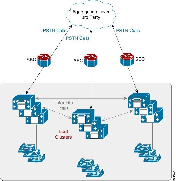
To understand the Cisco HCS Dial Plan Model, you must have a basic understanding of the Cisco HCS architecture and the interaction between the elements. The architecture consists of three discrete layers, the aggregation, infrastructure, and customer-premises layers, that comprise the majority of the call flow interactions. The aggregation layer handles inbound/outbound call routing between customer premises and PSTN, while all intracustomer interactions are handled at the infrastructure layers. The Cisco HCS numbering plan facilitates this design, allowing for a simple routing methodology, and is discussed in this section.
- Aggregation Layer
- Infrastructure Layer: Unified Communications Manager - Leaf Clusters
- Customer Premises Layer
- VoiceMail - Cisco Unity Connection
Aggregation Layer
The aggregation layer is responsible for the following:
-
E.164 call routing
-
Routing E.164 calls between two Hosted Collaboration Solution customers
-
Routing calls from the PSTN to IP Lines on Cisco Unified Communications Managerclusters
-
Routing calls from IP Lines (on Cisco Unified Communications Manager clusters) to centralized PSTN breakout
-
Routing calls to other components within the aggregation layer
-
Routing calls to Cisco WebEx (can be a separate route)
-
Routing calls to Cisco Contact Center Enterprise (can be a separate route)
The primary use of the aggregation is to aggregate central PSTN traffic. Any call that is received at the aggregation layer must be treated as a call either from or to the PSTN. The aggregation supports PSTN breakout like SS7 and SIP.
A service provider using Cisco Unified Communications Domain Manager 10.6(x) can only use the customer's own aggregation device (third party).
The aggregation layer is connected to the UC applications through the Cisco Unified Border Element (Service Provider Edition) as shown in the following figure. The Cisco Unified Border Element (Service Provider Edition), and the Cisco Unified Border Element (Enterprise Edition) in the case of a Micro Node deployment, are used mainly as a media aggregation point in Cisco HCS. The Cisco Unified Border Element is used for media anchoring and VRF translation functions. Additionally, it provides SIP header normalization functions for interoperating with various service provider networks. The Cisco Unified Border Element (Service Provider Edition) is configured manually; it is not provisioned automatically from Cisco Unified Communications Domain Manager. For signaling, there is one-to-one mapping of trunk from leaf clusters to signaling aggregation node, PGW, IMS or any other softswitch. In general, there is no dial plan requirement for Cisco Unified Border Element (Service Provider Edition).
 Note | The Forced On-Net feature in Cisco Unified Communications Manager can be used between users of a customer; that is, a user dialing the PSTN number of another user of the same customer. |
Calls between various clusters and the aggregation traverse SIP trunks. SIP is the only protocol that must be configured for these types of trunks.
Infrastructure Layer: Unified Communications Manager - Leaf Clusters
At the infrastructure layer, the Unified Communications Manager is used to service Cisco Unified IP phones and lines. The Unified Communications Manager routes calls to local PSTN, out to local gateways if connected, and handles all E.164 to internal DN translations. The leaf clusters must also integrate into Cisco Unity Connection, Cisco Unified Communications Manager IM and Presence Service, and Cisco Emergency Responder.
The incoming trunk from aggregation contains the e164Lookup partition, which converts E.164 to DN and points to InterSiteRouting CSS containing the InterSiteRouting partition. The InterSiteRouting partition contains the translation pattern pointing to IncomingToSite CSS which contains the site partition. For the Generic Dial Plan (G1), the DN is in the site partition.
For the Shared Instance Dial Plan (G3) some differences exist in routing. The Shared Instance Dial Plan (G3) is used for deployments that have shared instance clusters. In such deployments, multiple customers are deployed on one instance of Cisco Unified Communications Manager Virtual Machine. The Shared Instance Dial Plan is based on the Flat Dial Plan (G2) which is modified to support customer-specific dialing and routing.
For customer-to-customer calls within the same cluster using the Shared Instance Dial Plan (G3), even if two customers are on the same cluster, the routing requirements are that the calls from one customer should be routed to aggregation toward the PSTN, and then the calls should be routed back as inbound PSTN calls.
Intercluster Trunks (ICT) must be used to mesh the leaf clusters together. All intercluster intersite traffic that is dialed as Internal Unified Communications Manager DN must traverse the meshed ICTs.
All calls from the PSTN through the aggregation layer traverse SIP trunks through Cisco Unified Border Element Service Provider Edition to the leaf clusters. These trunks are marked as off-net trunks.
When an internal call is made on the leaf cluster, if the caller dials only the extension number, then the call is routed within the caller’s location. If the caller dials the Internal Unified Communications Manager DN, preceded by an intersite prefix built into site code, then the originating cluster routes the call to the correct location based on the mapping of site code to location.
Generic Dial Plan (G1) and Flat Dial Plan (G2) internal calls are routed based on the Line CSS that contains the InterSiteRouting partition. All the DNs for a customer reside in this partition.
Shared Instance Dial Plan (G3) internal calls are routed based on the Line CSS that contains the customer-specific site partition. All the DNs for a customer reside in this partition.
Legacy PBX connected to a dedicated PGW per customer has all E.164 calls between the Legacy location and the Cisco Unified Communications Manager location (even within the same customer) traverse the aggregation layer.
Customer Premises Layer
This layer connects customer endpoints—phones, mobile devices, and local gateways to the SP network—and provides end user interfaces to network management software. This layer may handle PSTN routing and Survivable Remote Site Telephony (SRST) if a local breakout design is used. This layer can also include C-series servers for Unified Communications Applications as part of the Cisco HCS Extender deployment model.
VoiceMail - Cisco Unity Connection
Cisco Unity Connection is connected to the leaf clusters as a SIP connection (telephony integration). For each Cisco Unified IP Phone line that exists on the leaf cluster that requires voicemail, there is also a voice mailbox definition on the Cisco Unity Connection. On Cisco Unity Connection, the voice mailbox definition is associated to the telephony integration and leaf cluster that contains the line definition. The leaf clusters have a voicemail Pilot Number defined that helps to route calls to the Cisco Unity Connection. With this scenario, each leaf cluster can use the same number for the voicemail pilot number.
Note | For Shared Instance Dial Plan (G3) dial plan, the voicemail pilot number can be shared within a customer (that is, across locations) but it has to be unique across customers that belong to the shared instance of Cisco Unified Communications Manager and Cisco Unity Connection. |
Numbering Plan Design
Directory Number
The Cisco HCS dial plan creates directory numbers (Unified Communications Manager Internal DNs) consisting of a Site Location Code (SLC) + extension number for the Generic Dial Plan (G1) and just the extension number for the Flat Dial Plan (G2) on Unified Communications Manager clusters. The directory number can be configured with or without an intersite prefix (see Intersite Prefix) as part of the SLC.
For more information on the Generic Dial Plan (G1) see Generic Dial Plan (G1).
For more information on the Flat Dial Plan (G2) see Flat Dial Plan (G2).
For more information on the Shared Instance Dial Plan (G3), see Shared Instance Dial Plan (G3). The Shared Instance Dial Plan (G3) works the same as the Flat Dial Plan (G2) except where noted in this guide.
Extension Numbers
An extension number is composed of one or more digits in the range 0 to 9 and must be unique within a site, although the same extension number can exist in multiple sites (that is, overlapping extension numbers). The length is determined on a site-by-site basis.
Extension number ranges chosen should not overlap with the intersite prefix or with PSTN access prefixes. To prevent overlap, do not use extension number ranges starting with a PSTN access prefix such as 9, or the chosen intersite prefix, commonly 8. Overlap between extension numbers and the emergency number at any location must be avoided. For example, if the emergency number is 112, then extension 112 or extension number ranges 112X (where X is one or more digits) are not permitted.
For a Flat Dial Plan (G2), the extensions and the internal DNs are the same. Extensions under Flat Dial Plan (G2) cannot overlap and have to be unique across all locations for a customer.
For a Type 4 Flat Dial Plan, the extensions and the internal DNs are the same. Extensions under Flat Dial Plan cannot overlap and have to be unique across all locations for a customer.
Site Location Codes
A Site Location Code (SLC) is a number composed of one or more digits in the range 0 to 9, used to prefix the extension number to create a unique directory number (DN). This enables the same extension number to exist in multiple sites (that is, overlapping extension numbers). Only one SLC is allowed at each site, and the SLC must be unique within the customer. An SLC is used to group a set of DNs to a site that has similar characteristics. The length may be determined on a site-by-site basis. Unified Communications Domain Manager does not allow a site code to be created that has either of the following characteristics:
-
Has a first portion that matches an existing site code
-
Matches the first portion of an existing, longer site code
For example, if site code 123 already exists and the user attempts to create site code 12, then the provisioning system does not allow it because site code 12 matches the first portion of 123. Similarly, if the user attempts to create site code 1234, then the provisioning system does not allow it because the existing site code 123 matches the first portion of 1234.
The restrictions above are required to prevent calls from being routed to the wrong site partitions due to overlapping numbers.
Note | Within the document, site and location are used interchangeably. |
Note | There are no SLCs for Flat Dial Plan (G2). |
Note | There are no SLCs for Flat Dial Plan (Type 4). |
Full National Number
In Cisco Unified Communications Domain Manager and the HCS Dial Plan model, Full National Number (FNN) is a subscriber number and does not include the area code. FNN is used in Number Construction with other options to build the External Phone Number Mask on Unified Communications Manager.
E.164 Number
The Cisco HCS dial plan is structured such that the calling and called party numbers for all inbound PSTN calls entering the Unified Communications Manager are in an E.164 format. The conversion to E.164 takes place at the aggregation layer or local gateway. Similarly, the calling and called party numbers for all outbound PSTN calls leaving the Unified Communications Manager are also in an E.164 format. The conversion to E.164 takes place at the Unified Communications Manager.
The format of the E.164 number is: +#COUNTRY##NATCODE##FNN#, where
+—International Escape Character
#COUNTRY#—Country Code (1 for United States, 44 for United Kingdom, and so on)
Note | Some countries do not use area codes; for example, Singapore. |
Intersite Prefix
The intersite dialing prefix (ISP) is optional and customer wide, and it tells the dial plan that the user is making an on-net call, and that the digits to follow must be in the format of a site location code (SLC) and an extension number. The ISP is a single digit number in the range 0 to 9 and must be unique within the customer's network. The ISP is deployment configurable to any value, but must not overlap with the PSTN dialing prefix or emergency number. The ISP is an optional configurable value within a customer's dial plan.
Note | Customer wide means that the same ISP must be used for all of a customer's sites. If the first site that is provisioned begins with the digit 8, then all other sites should also begin with the digit 8. Under one service provider you can have the ISP as 7 for one customer and 8 for another customer. |
Note | ISP does not apply to Type 4 Dial Plans. |
PSTN Access Prefix
The PSTN prefix is defined on a country basis. It is specified for each service provider for each country and each customer in the country. When the caller dials a PSTN number with a PSTN access prefix (typically a 9 in the United Kingdom and United States), this tells the dial plan that the caller is making an off-net call.
When the caller dials the PSTN breakout number, the dial plan routes the call to the correct PSTN breakout location, whether it is a central or a local PSTN gateway.
Open and Closed Dialing Plan and Numbering Plan Formats
An open dialing plan uses different dialing arrangements for local and long distance telephone calls, whereas a closed dialing plan is one in which the subscriber's full number is used for all calls, even in the same area. For example, in an open dialing plan you could dial 222-1234 for a local call and dial 1-212-222-1234 for a long distance call. In a closed dialing plan you would dial the same number for both local and long distance number. Some countries like Denmark do not have area codes; they dial the same number for local and long distance.
Open and closed dialing plans should not be confused with open and closed numbering plans. An open numbering plan features variance in the length of area code or local number, or both; for example in Great Britain, telephone numbers can be 9, 10, or 11 digits, depending on where the call originates.
A closed numbering plan, such as found in North America, imposes fixed-length area codes and local numbers; for example, United States telephone numbers are always 10 digits, which includes a 3-digit area code and a 7-digit telephone number. Some countries are moving from an open numbering plan to a closed numbering plan because a closed numbering plan is much easier to manage.
Cisco HCS Numbering Considerations
Cisco Unified Communications Manager numbering allows for the following dial patterns:
-
PSTN access prefix + STD1 access prefix + national number (for example, 902081231234 in United Kingdom and 914082221234 in United States)
-
PSTN access prefix + service code (for example, 9118500 in United Kingdom and 9611 in United States)
-
PSTN access prefix + emergency number (for example, 9999 in United Kingdom and 9911 in United States)
-
Emergency number (for example, 999 in United Kingdom and 911 in United States)
-
Intersite prefix + site code + extension (for example, 8 700 1000)
-
Extension number (for example, 1000) - Used for intrasite dialing. Flat dial plan it is used for both intrasite and intersite dialing
- Generic Dial Plan (G1)
- Flat Dial Plan (G2)
- Shared Instance Dial Plan (G3)
- Setting Up Number Construction in Cisco Unified Communications Domain Manager
- Multiple Service Provider Support
- Associate Dial Plan to a Service Provider
Generic Dial Plan (G1)
The Generic Dial Plan (G1) model allows you the ability to customize your dial plan.
Generic Dial Plan (G1) Number Construction
All directory numbers, voice mail pilots and mailbox numbers follow the SLC + extension format when they are provisioned from Unified Communications Domain Manager under the Generic Dial Plan (G1).
| Customer | Site Location Code (SLC) | Extension | Unified Communications Manager Configured DN Range |
|---|---|---|---|
| Customer 1 | |||
| Location 1 |
80101 |
1000-1999 |
801011000 - 801011999 |
| Location 2 |
80102 |
2000-2999 |
801022000 - 801022999 |
| Customer 2 | |||
| Location 1 |
80201 |
1000-1999 |
802011000 - 802011999 |
| Location 2 |
80202 |
2000-2999 |
802022000 - 802022999 |
Note | A standalone ISP is not supported, but rather, the ISP is implemented as the first digit of the SLC (ISP=8 in the preceding table). Note that you can have various digits as the first digit of the SLC; an ISP does not have to be used. |
Generic Dial Plan (G1) Customization
The Generic Dial Plan (G1) has the ability to leverage the Enhanced Number Translation (ENT) feature. The following ENT templates can be used:
-
Allow Call Template
-
Block Call Template
-
Local Calling Template
Local Calling via Local Break-Out (LBO) Template
-
Short Code (SC) Dialing Template
-
Voice Mail (VM) Dialing Template
VM Short Code Dialing Template
-
Intercluster Trunk Route Patterns ( ICT RP) Template
Intercluster Trunk Unmanaged Route Patterns Template
Intercluster Trunk VM Route Patterns Template
-
Intra Site Template
-
Inter Site Template
-
Intra Site Extension Prefix Template
-
Tail End Hop Off Route Pattern (TEHO RP) Template
Calling Party Screening Template
Small Contact Center (CC) RP Template
vPGW Unmanaged Location RP Template
Flat Dial Plan (G2)
The Flat Dial Plan (G2) model provides a second option of number construction. Flat dialing consists of flat 4- to 11-digit dialing across all locations. The Flat Dial Plan (G2) supports random unique directory number assignment across locations.
Flat Dial Plan (G2) Number Construction
All directory numbers, voice mail pilots and mailbox numbers follow the extension format when they are provisioned from the Unified Communications Domain Manager under the Flat Dial Plan (G2). The SLC was removed from the Unified Communications Manager internal number format.
| Customer | Extension | Example of a DN configured on Unified Communications Manager |
|---|---|---|
| Customer 1 | ||
| Location 1 |
16023421000-16023429999 |
16023429236 |
| Location 2 |
13363421000-13363429999 |
13363425022 |
| Customer 2 | ||
| Location 1 |
12123423000-12123423999 |
12123423044 |
| Location 2 |
2000-2999 |
2050 |
Note | The Flat Dial Plan (G2) Internal Number Format rules section uses a Site Location Code (SLC) to form the Unified Communications Domain Manager internal number format. The SLC does not get provisioned to the Unified Communications Manager and is solely for use by the Unified Communications Domain Manager to construct unique internal numbers across the system for various customers. Therefore, when provisioning customers in the Unified Communications Domain Manager under the Flat Dial Plan (G2), create a range of "dummy" SLCs and allow Cisco Unified Communications Domain Manager to auto select the SLC when creating locations. |
Flat Dial Plan (G2) Customization
The Flat Dial Plan (G2) has the ability to leverage the Enhanced Number Translation (ENT) feature. The following ENT templates can be used:
-
Allow Call Template
-
Block Call Template
-
Local Calling Template
Local Calling via Local Break-Out (LBO) Template
-
Short Code (SC) Dialing Template
-
Voice Mail (VM) Dialing Template
VM Short Code Dialing Template
-
Intercluster Trunk Route Patterns ( ICT RP) Template
Intercluster Trunk Unmanaged Route Patterns Template
Intercluster Trunk VM Route Patterns Template
-
Tail End Hop Off Route Pattern (TEHO RP) Template
Calling Party Screening Template
Small Contact Center (CC) RP Template
vPGW Unmanaged Location RP Template
Shared Instance Dial Plan (G3)
The Shared Instance Dial Plan (G3) is used for deployments that have Shared Instance clusters. In such deployments, multiple customers are deployed on one instance of Cisco Unified Communications Manager Virtual Machine. The Shared Instance Dial Plan (G3) is based on the Flat Dial Plan (G2), which is modified to support customer-specific dialing and routing. In this guide, the Shared Instance Dial Plan (G3)works the same as the Flat Dial Plan (G2) except where specified.
Shared Instance Dial Plan (G3) Customization
The Shared Instance Dial Plan (G3) has the ability to leverage Enhanced Number Translation templates. The following ENT templates can be used:
- Allow Call template
- Block Call template
- TEHO RP template (not available with per-customer SIP trunks)
- Local Calling template
- Forced Authorization Code using the Translation Pattern method template
-
Forced Authorization Code using the Route Pattern method template. For more information, see Cisco Hosted Collaboration Solution, Release 10.6(1) Features for Shared Instance Cisco Unified Communications Manager
Multicountry Support in Shared Instance Dial Plan (G3)
The Shared Instance Dial Plan (G3) provides multicountry support but not multicluster, multicountry support. For a customer, you can provision one site in one country and another site in another country, as long as both sites are on the same cluster.
Setting Up Number Construction in Cisco Unified Communications Domain Manager
The number construction rules in Cisco Unified Communications Domain Manager must be set for a Cisco HCS configuration. Click the Dial Plan Tools > Number Construction menu on the left navigation pane, and then click on the loaded dial plan.
Internal Number Construction
Cisco Unified Communications Domain Manager uses an internal number (FINT, FNN).
Cisco Unified Communications Domain Manager uses special terminology in dealing with number construction of this internal number:
-
CPID—Call Processing ID. This is assigned to hardware as required (PBX, Cisco PGW, Voicemail, and so on). The CPID is generally configured when you add the hardware and is displayed when you view the settings.
-
RID—Routing ID. This ID is selected for a location and is unique for the CPID. In the case of a location, the RID could be an available RID for the CPID of the IPPBX of the location. The RID that is assigned to a location can be viewed on the location details page in the Dial Plan section.
-
Site Code—This is a location level code assigned for each location. The site code inventory is managed for each customer in Unified Communications Domain Manager. The length of the site code is always allowed to be variable with a defined maximum length. Overlapping site codes are not allowed within a single customer. The site code for a location can be viewed on the location details screen in the Dial Plan section.
-
CID—Cluster ID. This ID is assigned to each Cisco Unified Communications Manager PBX cluster in the system. This is configured when you add the cluster and is viewed on the cluster details page.
-
FINT—The full internal number. Unified Communications Domain Manager uses the FINT number of the lines to recognize the location. The construct of this is defined in the number construction rules. When a location is added, the full FINT inventory is created for the location.
-
FNN—The full national number (PSTN number).
Cisco HCS Configuration of Number Construction Elements
The following number construction elements are applied when using the G1, G2 or G3 Dial Plan model sheet for Cisco HCS. These values can also be entered through the GUI.
Multiple Service Provider Support
The Cisco Unified Communications Domain Manager supports one Cisco HCS Dial Plan Model per service provider. Unified Communications Domain Manager can also be configured to support multiple service providers. Cisco HCS can take advantage of multiple service provider support capability to support multiple Cisco HCS Dial Plan Models. You can create a service provider for each Cisco HCS Dial Plan Model that is required.
Cisco HCS supports two Cisco HCS Dial Plan Models based on different number construction.
To achieve support for different dial plans in a Unified Communications Domain Manager system, create two or more service providers with a respective hardware set and dial plan association assigned.
Before creating the service provider, load the base data models to create the number construction and hardware set in Unified Communications Domain Manager. The number construction instructs Unified Communications Domain Manager to build internal system numbers and Unified Communications Domain Manager directory numbers (DNs). Hardware sets define the templates for the system to adopt in terms of the types of hardware configurations and they also define the associated dial plans for each hardware set.
After the number constructions and hardware sets have been loaded into Unified Communications Domain Manager through the base data models, service providers can be configured in the system.
Note | A hardware set can have multiple dial plans associated to it. |
Considerations When Deploying Multiple Service Providers
Role Based Access Control (RBAC) stays within a service provider domain. Cisco Unified Communications Domain Manager maintains different hierarchy levels at which configuration objects are managed. The following levels are possible:
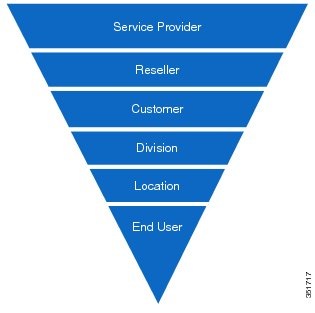
The internal system super user maintains visibility and control of all service provider hierarchical domains for the entire system. Each service provider domain can have administrators at the different provider, reseller, and customer location levels but are constrained to their parent service provider. For example, service provider Admin1 in service provider 1 cannot manage or provision elements for service provider 2 and vice versa.
Associate Dial Plan to a Service Provider
When you create a service provider linking a hardware set, associate the dial plan to the service provider.
For more information, see Multiple Service Provider Support.
Numbering at the Cisco Unified Communications Manager Interface
The following table describes the numbering format at the Cisco Unified Communications Manager interface:
|
Site code and extension. No + for SIP, NOA = unknown for Q.931 |
Site code and extension. No + for SIP, NOA = unknown for Q.931 |
||
|
Site code and extension. No + for SIP, NOA = unknown for Q.931 |
Site code and extension. No + for SIP, NOA = unknown for Q.931 |
||
|
Full E.164. + for SIP, NOA - international for Q.931, prefix 9 for DPNSS |
Site code and extension. No + for SIP, NOA = unknown for Q.931 |
||
|
Site code and extension. No + for SIP, NOA = unknown for Q931 |
|||
|
Full E.164. + for SIP, NOA - international for Q.931, prefix 9 for DPNSS |
Either site code and extension No + for SIP, NOA = unknown for Q931 for internal originator Or Full E.164. + for SIP, NOA - international for Q.931 for PSTN originator |
Unified CM site code and extension. No + for SIP, NOA = unknown for Q.931 |
Cisco PGW Model and Call Routing
This section describes how the Cisco vPGW dial plan is designed and implemented for Cisco HCS.
Note | PGW and virtualized PGW (vPGW) are used interchangeably in this Guide. |
The Dial Plan design provides basic functionality to meet customer requirements for calling and called number analysis. The Dial Plan also enables the creation of permutations of combined open and closed numbering plans, and the ability to easily modify them. The Cisco Media Gateway Controller (MGC) Dial Plan design also provides the interface to a real-time database.
The Dial Plan is, of necessity, the final step in provisioning the MGC node. To create a Dial Plan, you must first determine what routes, trunk groups, and trunks are provisioned in the MGC. The MGC provisioning information provides a logical representation of the actual routes, trunk groups, and trunks on the media gateways that are controlled by the MGC.
The routing plan types that are developed during provisioning of the MGC determine what trunks in a media gateway are assigned to a specific trunk group, and what trunk groups are assigned to what routes. The routes determine what originating and terminating points are serviced by the MGC.
All required routes, trunk groups and trunks are created manually on the Cisco vPGW softswitch.
The Dial Plan determines how each call that comes into the MGC is processed. Call processing rules in Dial Plans are static, but the events that determine how each call is ultimately processed are dynamic, and depend on several factors within and external to the MGC.
Before you can build a Dial Plan, you must understand the functions that the Dial Plan can perform:
Cisco PGW Dial Plan Design
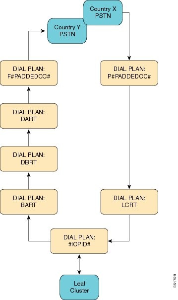
Each time a Unified Communications Manager is connected to the Cisco PGW Softswitch or Cisco Virtualized PGW (vPGW) Softswitch, an associated Dial Plan is created; the name of the Dial Plan is the CPID of the cluster. This Dial Plan performs the following functions:
Based on the Dialed Number, the BART Dial Plan switches the call analysis between Origination Based Routing Table (OBRT) and Destination Based Routing Table (DBRT). Only DBRT is currently used; by default all PSTN calls are forced on-net if the number belongs to the Cisco HCS. Forced On-Net can be overwritten through the Forced Off-Net feature in Unified Communications Domain Manager. Further call analysis is performed by the Destination Based A number analysis Routing Table (DART) Dial Plan, which routes the call to the appropriate F<PADDEDCC> country Dial Plan, which handles call egressing to the PSTN.
Incoming PSTN calls are handled by the P<PADDEDCC> country Dial Plan. The Dial Plan does an A number Times Ten Database lookup for Fixed Mobile Convergence (FMC) feature and B number Times Ten Database lookup for normal incoming calls to Cisco HCS. If found, the call is forwarded to LCRT Dial Plan.
A Cisco PGW Dial Plan to analyze both calling and called number (A-number and B-number) to route calls either to a central PSTN breakout or a leaf cluster is assumed, with the following inbound and outbound call number format:
-
E.164 lookup to internal DN mapping is not done by the Cisco PGW. Lookup happens on leaf clusters.
-
Number normalization is done by the leaf clusters. Cisco PGW does minimal normalizations if required. The numbering format is as shown in the table that follows.
Table 5 Numbering Format Calls Numbering Format Calls from leaf cluster to Cisco PGW
Calls from Cisco PGW to leaf clusters
Calls from Cisco PGW to PSTN breakout (international format with + on SIP trunks, with leading 00 on other PSTN interfaces)
Calls from Central PSTN breakout to leaf clusters
International Calls (Normalize to append +)
-
Leaf clusters do not send R-Number to Cisco PGW for the redirected calls, so R-Number is not handled at Cisco PGW.
Cisco PGW Provisioning
Cisco Unified Communications Domain Manager provisions the PGW when the following events occur in the Cisco Unified Communications Domain Manager:
-
When the Cisco PGW is activated.
-
When a new Cisco Unified Communications Manager cluster is added to the Cisco PGW.
-
When a Country PSTN interconnection is added to the Cisco PGW.
-
When a PSTN number is associated with a Cisco Unified Communications Manager cluster.
Cisco Unified Communications Manager provisions the PGW when the following events occur:
Dial Plan Enhancements for vPGW
Deploying Virtualized PGW for Legacy PBX Support
Cisco HCS provides Legacy PBX support using Virtualised PGW (vPGW). The vPGW deployment is a dedicated per-customer deployment requiring Legacy PBX support. The PGW Legacy PBX support should not be deployed with the PGW that serves as an aggregator for off-net calls. In other words, PGW should only be used to support either Legacy PBX or Aggregation.
Changes to PGW Static Configuration
ConnectIPPBXTransit
For the ConnectIPPBXTransit to be successful, two route lists must be created in PGW:
Once the SIP trunks are created, it is important to associate them with the correct dial plans to ensure that calls are routed successfully:
- Incoming trunks from Cisco Unified Communications Manager to PGW Legacy should be associated with the EGRESSCUSTDIALPLAN2 dial plan. Value can be obtained by navigating to the Customer > Advanced Management > View PGW Config.
- Outgoing trunk from PGW Legacy to Cisco Unified Communications Manager should be associated with dial plan CCMO
- Incoming trunk from Cisco Unified Border Element to PGW Legacy should be associated with dial plan FPADDEDCC (for example, F044)
- Outgoing trunk from PGW Legacy to Cisco Unified Border Element should be associated with dial plan PPADDEDCC (for example, P044)
Below is an example configuration of the manual SIP Trunk required on the PGW. In the following example, the highlighted legend is as follows:
- 4000 = The Unique ID for the trunk group IN
- 4001 = The Unique ID for the trunk group OUT
- LCprof-6 = The 6 here is used to identify the profile that is associated with the IN and OUT groups, and needs to be unique
- 10.120.1.162 = This is the IP address of the Cisco Unified Communications Manager you are connecting to vPGW
- 5100 = The 5100 is the CPID defined in the system, of the Cisco Unified Communications Manager
- 000X = The EGRESS CUSTDIALPLAN2 configured for the Customer requiring Legacy PBX Support. This value can be obtained by navigating to the Customer > Advanced Management > View PGW Config
prov-add:trnkgrp:name="4000",type="SIP_IN",svc="sip-sigpath",clli="sip"
prov-add:profile:name="LCprof-6",type="SIPPROFILE",custgrpid="000X",MGCDomain="lc6.com",trustlevel="1",
				topologyhidingenabled="1",unsolicitednotifymethod="1"
prov-add:trnkgrpprof:name="4000",profile="LCprof-6"
prov-add:trnkgrp:name="4001",type="IP_SIP",svc="sip-sigpath",clli="sip"
prov-add:trnkgrpprof:name="4001",profile="LCprof-6"
prov-add:IPROUTE:NAME="ipr1-6-4001",DESC="IPRoute to 6
				6001",DEST="10.120.1.162",NETMASK="255.255.255.255",
				NEXTHOP="IP_NextHop1",IPADDR="IP_Addr1",PRI=1
prov-add:IPROUTE:NAME="ipr2-6-4001",DESC="IPRoute to 6
				6001",DEST="10.120.1.162",NETMASK="255.255.255.255",
				NEXTHOP="IP_NextHop2",IPADDR="IP_Addr2",PRI=2
prov-add:IPINMAPPING:NAME="sipin6-4001",DESC="",SIGSVC="sip-sigpath",ALLOWEDIP="10.120.1.162",
				ALLOWEDIPNETMASK="255.255.255.255",SIPPORT=5060,TRNKGRPNUM=4000
prov-add:siprttrnkgrp:name="4001",url="10.120.1.162",srvrr=0,sipproxyport=5060,version="2.0",cutthrough=2,
				extsupport=1
prov-add:rttrnk:weightedTG="OFF",name="rtetolc6-1",trnkgrpnum=4001
prov-add:rtlist:name="rtlist2pstn#PADDEDCC#5100",rtname="rtetolc6-1",distrib="ON"
Cisco Unified Communications Domain Manager Provisioning of Virtualized PGW for Legacy PBX Support
Configure Virtualized PGW
Before provisioning virtualized PBW, it is assumed that
- The components (vPGW, Cisco Unified Communications Manager, IOS Devices) all conform to the Cisco HCS versions stated in the Cisco HCS Compatibility Matrix.
- The latest 8.1.x-G1Model including IOS_15.x and PGW MML and Times Ten models have been loaded.
- Provider, Reseller, Customers, and Locations have been provisioned.
- Cisco Unified Communications Manager clusters are added with a CPID > 5000 or above.
- The Cisco Unified Communications Manager cluster has been connected to the Classic or Standard PGW if there is one in the network.
| Step 1 | Under Network > Transit, add the vPGW to the Provider network. |
| Step 2 | Choose the newly-added vPGW and load the initial configuration on vPGW. |
| Step 3 | Under Network > PBX Devices, add an Unmanaged PBX to mirror the legacy PBX. |
| Step 4 | Under Network > PBX Devices, choose the appropriate Unified Communications Manager device being used by the Customer. Select Connectivity and PBX > Transit. Connect Unified Communications Manager to vPGW. |
| Step 5 | Under Network > PBX Devices, choose the appropriate Unified Communications Manager device being used by the customer. Select Connectivity and PBX > Connection Destination. Add a Connection Destination. |
| Step 6 | Under Parent Connection > Trunks, add a Trunk with protocol = SIP, template = TovPGW-Legacy. |
| Step 7 | Under Parent Connection > Route Patterns, add a Route Pattern in the InterSiteRoutingPT partition toroute all calls beginning with “!” to the SIP trunk above. |
| Step 8 | Under Network > Hardware Groups, add Hardware Group with Action = “Adding Locations – Transit”.Choose the vPGW and Unmanaged PBX to be part of the Hardware Group. |
| Step 9 | Choose the customer requiring Legacy PBX support. Under Advanced Management > Hardware Groups, connect the customer to the new Hardware Group. |
| Step 10 | Add an Unmanaged Location using the above Hardware Group. |
Configure IOS Device
Use the following procedure to configure an IOS device. For the actions in this procedure, follow the steps documented in CUCDM IOS Gateways Guide for HCS 9.1(1).
| Step 1 | Under Network > IOS Devices, add a transit-controlled MGCP Device. Ensure that Gateway is the Device Role chosen. | ||
| Step 2 | Add IOS Gateway. Select MGCP as the protocol for legacy gateways. | ||
| Step 3 | Add
Legacy PBX
Hardware Configuration.
| ||
| Step 4 | Add and
configure legacy port settings.
|
Activate IOS Gateway
Cisco vPGW Softswitch Dial Plans
Cisco Unified Communications Domain Manager creates the dial plans shown in the following table on the Cisco vPGW Softswitch. Trunks are added manually and the trunk profiles are associated with respective dial plans like cluster CPID, P(PADDEDCC).
|
Leaf cluster routing for routing the call to the correct leaf cluster that owns the PSTN number. |
||
|
Destination and Origination based Routing Determination table. |
||
|
Adding Country Dial Plan to handle incoming and outgoing calls using the country specified interconnect. |
||
|
Provision Force Off-Net support, by default all calls are Force On-Net. |
||
|
Per-cluster Dial Plan, for handling calls to and from the cluster. |
Bulk Load Dial Plan and Platform Base Data Settings
To begin the initial system build, upload the Base Data loaders into Cisco Unified Communications Domain Manager. For details about base data loaders, refer to Bulk Loader Guide for Cisco Unified Communications Domain Manager 8.1.4.
Bulk Load HCS Dial Plan Models
For details about bulk load dial plan models, refer to Bulk Loader Guide for Cisco Unified Communications Domain Manager 8.1.4.
| Step 1 | Browse to . Select Schedule New Job. | ||
| Step 2 | Click the Browse button. | ||
| Step 3 | Upload the required set of dialplan loaders.
|
Cisco IOS Model and Call Routing
The Cisco IOS model is used to provision analog gateways and Cisco IOS gateways. Cisco IOS gateways can be deployed at each location and can be used for the local breakout (LBO) to PSTN (optional). An IOS gateway may be used to route IP phone connectivity to Cisco Unified Communications Manager and may be used as a DHCP server for local phones. Cisco IOS gateways can also be deployed to provide Survivable Remote Site Telephony (SRST), media resources, and legacy PBX (QSIG, DPNSS) connection gateways that are MGCP controlled.
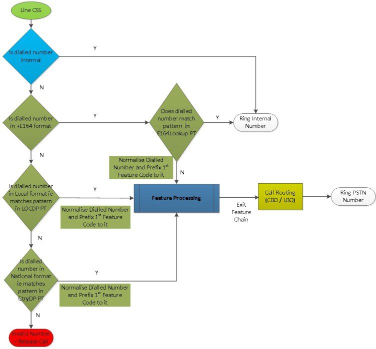
Looping Dial Plan Call Processing
The HCS 10.0 CUCDM 8.1(x) Looping CSS dial plan leverages the Use Originator's CSS feature of CUCM 10.0.
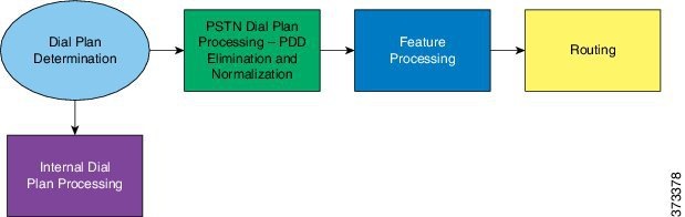
The call processing consists of the following stages as shown in the diagram below.
- Dial Plan Determination (Internal and PSTN dial plan), subsequent bullet points are only applicable to PSTN calls
- Origination Call Screening
- Country Dial Plan PDD elimination, Normalization and Call Type Classification
- Feature processing (i.e. Forced OnNet, COS, CLIP/CLIR, FAC, CMC and Security Screening)
- Line CSS based Routing (except Emergency Calls - Device CSS based)
The call processing is implemented as shown below.
Note | Features and Routing is based on Call Type rather than Dialed Number. |
Note | Features are independent of the country dial plan. |
Note | Country Dial Plan consists of only blocking and allow patterns. |
Dial Plan Determination
The first stage of call processing is the determination of which dial plan to apply against the incoming call.
- Option 1: Incoming Dial Plan Processing
-
Internal call handling is based on Flat Dial Plan.
- Option 2: PSTN Dial Plan Processing
-
PSTN Breakout code is used for dialing PSTN numbers. It is a single digit number and is country specific (i.e. PSTN breakout code is per country).
For example all Singapore locations will be configured with 9 as PSTN access prefix.
Note
The PSTN dialing prefix is set as an HCS system setting in the Country Dial Plan Base Data file and cannot be changed on a per tenant basis.
Internal Dial Plan
The HCS G2 dial plan requires unique extensions (including Voicemail pilot numbers) across all of the customer's locations. This uniqueness needs to be managed by the provider. Cisco Unified Communications Domain Manager will not enforce extension number uniqueness in the system.
Extension numbers lengths are variable but are fixed within a customer and can vary across different customers.
Country Dial Plan
Each country dial plan deployed will have a Country DP PT (CTRYDP4-#ISO#-PT) containing all country specific Translation Patterns for all call types except Local and for each site/location a Local DP PT (LOCLDP4-#ISO#-PT) containing Translation Patterns for Local dialing.
The objective of each pattern in these two partitions is to eliminate PDD, Normalize the Called Number, Prefix the first feature code (FONet) of the feature chain, the CLIP/CLIR indicator and the Call Type to the Called Number.
Site/Location specific Partitions for Emergency Dialing and AnalogLineCOS are also present.
All the above mentioned partitions have a time schedule set to 'All Day'.
Feature Processing
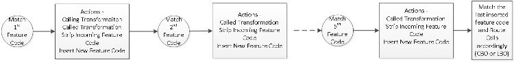
Feature Chaining Concept
The feature chaining concept is when a set of feature are link together to form a list of feature to be process sequentially. Each feature in the chain follows the following implementation guide:
- Each feature is made up of a feature component with or without a Time Schedule partition.
- Each feature code is implemented by a one or more Translation Patterns.
- Feature Code patterns are unique within the CSS.
- The Translation Patterns belonging to a feature strip the existing Feature code pattern and Prefix the next feature code pattern in the Called Number Transformation except for the last feature in the chain.
- The translation patterns of the first feature code in the chain matches the Feature code inserted by the Country Dial Plan. The Country Dial Plan prefixes the following pattern to the Normalized Called Number:
Where,
The first two digits is the 1st feature Code (FONet).
- 01 - International (Intl)
- 02 - National (Natl)
- 03 - Mobile (Mobl)
- 04 - Emergency (Emer)
- 05 - Service (SVC)
- 06 - Local (Locl)
- 07 - Premium Rate Service (PRS)
- 08 - Free Phone Numbers (FPN)
- 09 - Personnal Communication Service (PCS)
- 10 - Special Rate Service (SRS)
- 11 - Operator (OPR)
- 12 - International Restricted (IntlR)
The last set of digits is the IntlDialCode. The Country specific International Dial Code is present in the CtryDP Base Data xls.
All feature in the chain use the CSS Hierarchy feature except for the last feature in the Chain.
Feature that involves Route Pattern is the last combine feature of the chain.
- Forced OnNet Feature
- Originating Call Screening Feature
- ToD with CLIP/CLIR Feature
- Forced Authorization Code (FAC) Feature
- Client Matter Code (CMC) Feature
- Security Screening for Routing Feature
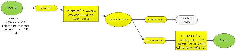
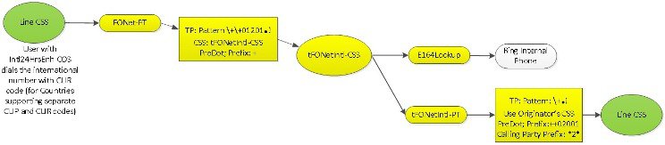
Forced OnNet Feature
This feature handles a user dialing a PSTN number of another user within the same organization. In the case of click to dial (assumption is that the number is in plus E164 format), Forced OnNet is always enforced via the inclusion of the E164LookUp partition in the Class of Service CSS in order to bypass the blocking partition.
Note | This feature handles the use case where a User with a particular COS dials the allowed numbers using PSTN breakout code and IDD/STD code. I.e. non-E164 number format. |
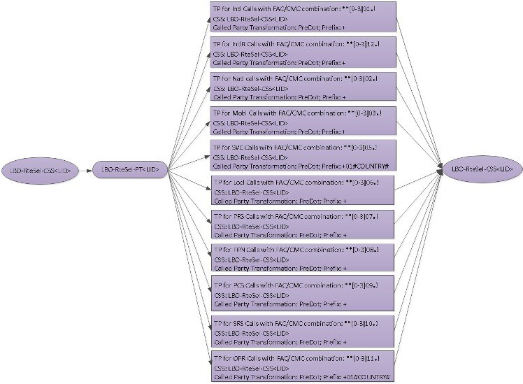
The Forced OnNet feature is only applicable for the Intl, Natl, Mobl, Locl and PCS call types.
The Forced OnNet feature does not do Forced OnNet for call types other than the ones listed i.e. SVC, PRS, FPN, SRS, OPR call types.
For the Intl, IntlR, Natl, Mobl, Locl and PCS call types the Forced OnNet feature is implemented as follows for the 3 CLIP/CLIR scenarios - default CLIP/CLIR COS, per call CLIP/CLIR and toggle CLIP/CLIR-
- a partition to handle Forced OnNet.
- a CSS and a partition for each Call Type.
- the E164LookUp and per Call Type partition associated to the per Call Type CSS. If the Called Number matches a pattern in the E164LookUp the call is Forced OnNet.
- the '\+.!' Pattern added to the per Call Type partition, which does a PreDot and Prefix the code of the next feature to the Called Number. This wild card patterns traps all calls that are not Forced OnNet for that Call Type. The pattern is mark to use 'Use Originator's CSS'. At this point, for security purpose, the Calling Number is prefixed with *2* and it (Calling Number) will be checked during the last feature (Security Screening) implementation
- Similar patterns added to the Forced OnNet partition to handle each supported Call Type.
- Each of these patterns remove the feature code and normalize it to plus E164 Called Number and send the call to the above per Call Type CSS.
Note | To simplify the diagrams in the sections of Stage2: Feature Processing and Stage3: Routing, the Line CSS is shown twice. |
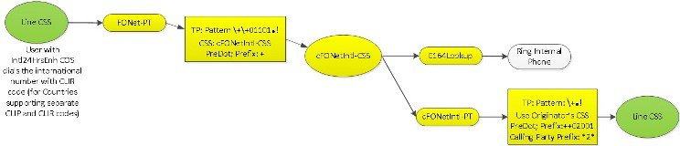
Similar flows are allowed in the dial plan for Users dialing International Restricted, National, Mobile, Local and PCS numbers in non-E164 format.
Originating Call Screening Feature
Originating Call Screening is achieved by using a combination of the available Blocking partitions and an Allow Partition.
Note | All blocking is 'All Day'. |
At present there are 11 blocking partitions associated with a specific Call Type and a Block All PSTN partition as follows:
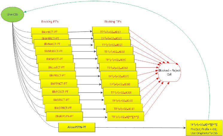
- BlkIntlCT-PT - Block International Call Type (01) Numbers
- BlkIntlRstCT-PT - Block International Restricted Call Type (12) Numbers
- BlkNatlCT-PT - Block National Call Type (02) Numbers
- BlkMoblCT-PT - Block Mobile Call Type (03) Numbers
- BlkSVCCT-PT - Block Service Call Type (05) Numbers - Any number that needs to be sent as Dialed excluding the PSTN Breakout Code)
- BlkLoclCT-PT - Block Local Call Type (06) Numbers
- BlkPRSCT- PT - Block Premium Rate Service Call Type (07) Numbers
- BlkFPNCT- PT - Block Free Phone Service (Toll Free) Call Type (08) Numbers
- BlkPCSCT- PT - Block Personal Communications Service Call Type (09) Numbers
- BlkSRSCT- PT - Block Special Rate Service Call Type (10) Numbers
- BlkOPRCT- PT - Block Operator Rate Service Call Type (11) Numbers
- BlkAllPSTN- PT - Block All PSTN Numbers
Note | Call Type 04 is for Emergency Calls but is not relevant for this feature as Emergency Calls use the Device CSS and are always allowed. |
Each of the above partition contains a set of Translation Pattern that blocks the specific call type associated to that partition.
For example, calls made to International number by a User with Natl24HrsEnh COS will be blocked.
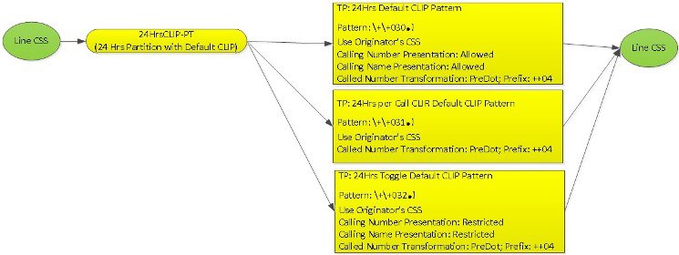
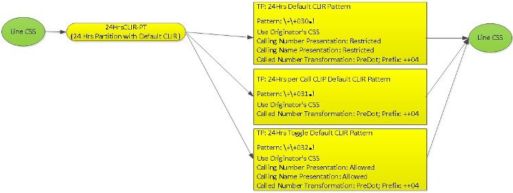
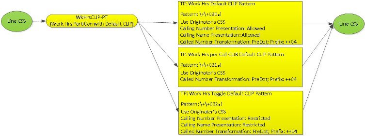
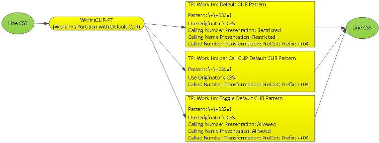
ToD with CLIP/CLIR Feature
- Two Time Schedules are created, i.e. 24 hours and Working hours.
- Each Time Schedule support two partitions, one for handling Default CLIR and the other for Default CLIP.
- Each partition contains three patterns to handle the Feature Code ++030, ++031 and ++032, by modifying the Calling Name and Number Presentation.
- Each translation pattern in turn prefixes code for the next feature (FAC) in the chain.
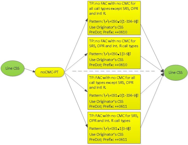
Forced Authorization Code (FAC) Feature
The fourth feature that consumes the above feature code is the FAC feature. Depending on the COS assigned to the worker type, he/she can either dial the destination numbers without having to enter the FAC codes OR can dial the destination numbers only after entering the FAC codes.
-
FAC Feature Code is ++04.
-
The FAC feature supports two partitions, one for handling all call types without FAC and the other for handling all call types with FAC.
-
Each partition contains two translation patterns to handle all the call types.
-
For all call types without FAC, the two translation patterns in the noFAC-PT prefix the called number with ++050 code for the next feature (CMC) in the chain. Figure 14. no FAC for all Call Types 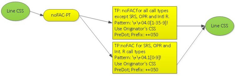
-
For all call types with FAC, the two translation patterns in the FAC-PT prefix the called number with ++051 code for the next feature (CMC) in the chain. Figure 15. FAC for all Call Types 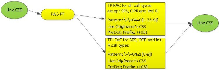
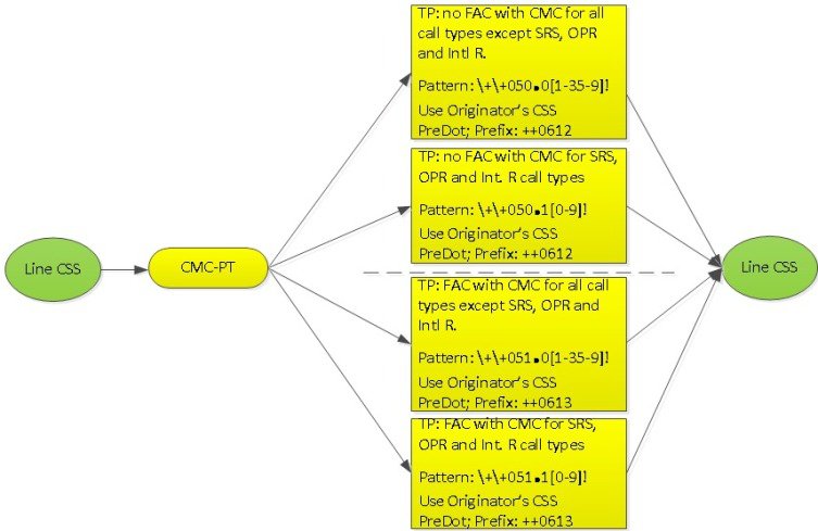
Client Matter Code (CMC) Feature
The fifth feature that consumes the above feature code is the CMC feature. Depending upon the COS assigned to the worker type, he/she can dial the destination numbers using either of following FAC/CMC codes combination.
Similar to FAC handling, the CMC feature supports two partitions.
The partition CMC-PT has four translation patterns shown below of which two are for handling no FAC with CMC combination for all call types - Called Number Prefix with ++0612 and the other two translation patterns are for handling FAC with CMC combination for all call types - Called Number Prefix with ++0613.
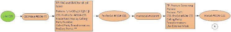
Security Screening for Routing Feature
Prior to routing the call either using Central Breakout (CBO) or Local Breakout (LBO), the last feature in the feature chain does the following
- For all call types (with all FAC/CMC combinations), the call is routed based on Calling number
- For CBO, the Calling number is screened to check if it is prefixed with *X* and For LBO, the Calling number is screened to check if it prefixed with a more specific pattern *2*.
- Transforms the Called Party Number for all call types (except Service and Operator) by doing a PreDot discard and prefixes +
- Transforms the Called Party Number for Service and Operator Call Types by doing a PreDot discard and prefixes +#COUNTRY#
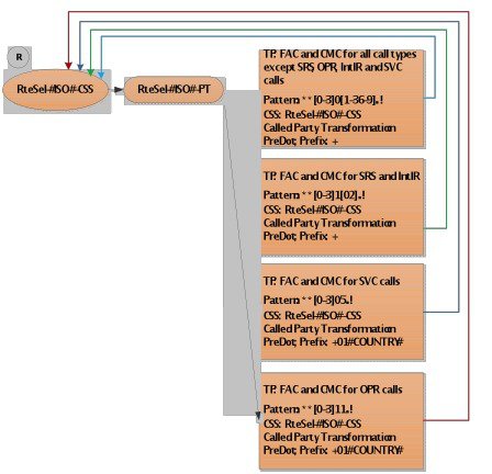
Note | Depending on Customer requirement to route specific call types with a particular FAC/CMC combination, more specific Route Patterns can be used to override the catch all Translation Patterns for Call Types and all FAC/CMC combinations. For CBO, this can be done using Generic SIP Trunk as shown in Stage 3: Routing section. |
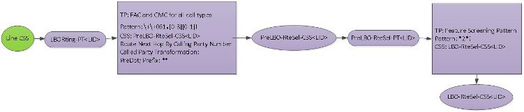
Note | To simplify the Called Number modified diagram, the LBO-RteSel-CSS<LID> is shown twice instead of showing the Translation Patterns return to the same CSS. |
Note | Depending on Customer requirement to route specific call types with a particular FAC/CMC combination using LBO, more specific Route Patterns can be used to override the catch all Translation Patterns for Call Types and all FAC/CMC combinations. For LBO, this can be done using ENT template as shown in the Stage3: Routing section. |
Routing
The routing is done in the following ways for CBO and LBO.
Central Break Out (CBO)
The routing of all call types without FAC/CMC is achieved using the Route Patterns, Route Lists, Route Groups, Trunks defined in the Generic SIP trunk.
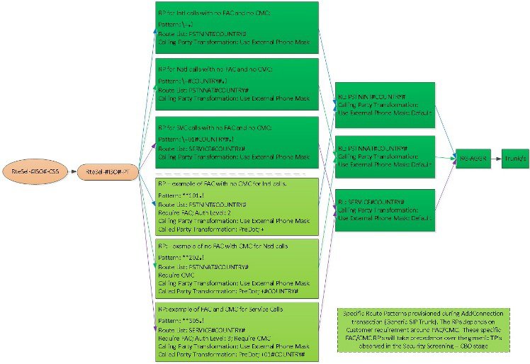
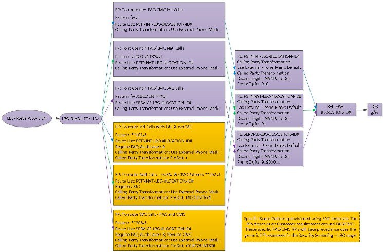
Local Break Out (LBO)
The routing of all call types without FAC/CMC is achieved using the Route Patterns, Route Lists, Route Groups, IOS g/w defined in the Generic Leaf Cluster Model.
Other Considerations
There are several considerations to the current Dial Plan Model. Some of the considerations and their impact are listed in the following table.
|
Item |
||
|---|---|---|
|
This limit affects migration of customers from one release to another. After the new Dial Plan Model is loaded, all customers on the previous model must migrate to the new model. |
||
|
The number construction rules define how an internal DN, site codes, display policies, and so on are constructed. |
The rules limit how Internal DNs are constructed, how calling party number appear for intrasite calls, intersite calls, and so on. |
|
|
Dial prefixes include: Extension prefix, Intersite prefix, and PSTN prefixes. |
The PSTN prefix is currently defined at a Country Level. All customers within the same country have to dial the same PSTN prefix. If ISP is used, the extension prefix is supported using ENT templates. There is no support for Extension Prefix in the current model. |
Subscriber Trunk Dialing (STD) prefix for UK is 0 and for US is 1. STD is optional; some countries do not use an STD prefix.
 Feedback