Accessories

Bluetooth Accessories

Users can pair Bluetooth accessories, such as headsets, keyboards, and mobile phones, to their DX Series devices.

Users can pair multiple Bluetooth devices at one time, however they may only pair one Bluetooth audio device at a time.

Enabling Bluetooth may degrade a wireless network connection. For improved wireless network performance, users should disable Bluetooth when it is not in use, or use the 5 GHz band for their wireless network connection.

Bluetooth Device Profiles

The Device Profile Settings screen shows the profiles that are available for a paired device. If you disable a profile, the profile is unchecked and the user cannot enable it.

Handsfree Profile

Cisco DX Series devices support various Handsfree Profile features that enable you to use accessories (such as Bluetooth wireless headsets and Bluetooth-capable mobile phones) to perform certain tasks without the need to handle the device. For example, rather than tap Redial on the device, users can follow instructions from the headset manufacturer to redial a number from their Bluetooth wireless headset.

These hands-free features apply to Bluetooth accessories:

  • Handle Bluetooth HFP connected/disconnected status.

  • Dial a phone number on the Audio Gateway (AG) to make a call.

  • Indicate when a call is connected or disconnected.

  • Notify an application when a call is incoming (inband ringtone).

  • Enable or disable inband ringing.

  • Report phone status (such as caller ID, signal strength, and battery level, from the AG).

  • Answer or reject calls.

  • Receive call-waiting notification with caller ID.

  • Put a call on hold and switch to a waiting call.

  • Switch between calls on hold and active calls on the AG and in the Call application.

  • Switch audio to the mobile phone and return audio back to the Hands-Free Unit.

  • Retrieve the mobile phone call list.

Hands-free devices may differ as to how features are activated. Device manufacturers may also use different terms to refer to the same feature. For more information, see the manufacturer documentation.

Phone Book Access Profile

Bluetooth Phone Book Access Profile (PBAP) allows the user to share contacts and call history from a paired mobile phone to a Cisco DX Series device. The user can choose to download contacts and call history manually or automatically when they pair their mobile phone, and can choose to save the contacts on their device.

Enable Device Profiles

Procedure

Step 1

In Cisco Unified Communications Manager Administration, choose Device > Phone, locate the device you want to modify, and go to the Phone Configuration window for that device.

Step 2

In the Phone Configuration window, choose Enable for the Bluetooth setting.

Step 3

Enable a device profile.

Step 4

Save your changes.


Pair Bluetooth Accessory

Procedure


Step 1

In the Settings application of the device, toggle Bluetooth on.

Step 2

Tap a device to pair from the available devices list.

Step 3

Verify the passkey and tap Pair.


Disable Bluetooth

Procedure


Step 1

In Cisco Unified Communications Manager Administration, choose Device > Phone.

Step 2

In the Find and List Phones window, enter the search criteria for the device that you want to modify, and then click Find.

Step 3

In the Product Specific Configuration Layout area of the Phone Configuration window, choose Disabled from the Bluetooth drop-down list box.


Cable Lock

You can use a laptop cable lock to secure the device to a desktop. The lock connects to the antitheft security connector on the back of the device and the cable can be secured to a desktop.

The security slot can accommodate a lock up to 20 mm wide. Compatible laptop cable locks include the Kensington laptop cable lock and laptop cable locks from other manufacturers that fit into the security slot on the back of the device.

External Cameras

Cisco DX650 supports the add-on Logitech C920-C Webcam or Logitech C930e as an external camera.

The external camera connects to the device and allows the user to make a point-to-point video calls. For the external camera to work, video calling and USB devices must be enabled.


Note

If the Cisco DX650 is powered by Power over Ethernet, the external camera requires 802.3at. If the phone is not powered by Power over Ethernet, the external camera requires an external power supply.

External Camera Settings

After you attach the external camera to the device, the user can control the settings of the external camera. Unlike the internal camera, the brightness setting for the external camera cannot be adjusted.

Perform External Camera Postinstallation Checks

Procedure


Step 1

Wait until the External Camera Connected message appears.

Step 2

In the Call application, tap More.

Step 3

Tap Self view.

Step 4

Move the device and external camera to a position where no bright lights are in the field of view.

Step 5

Move the device and external camera so that the user is illuminated from the front.


External Speakers and Microphone

External speakers and microphones are plug-and-play accessories. You can use the line in/out jack to connect an external PC-type microphone and powered speakers (with amplifier) on the device. Connection to an external microphone disables the internal microphone, and connection to an external speaker disables the internal speaker.


Note

Use of poor-quality external audio devices, use of loudspeakers at very loud volumes, or placement of the microphone very close to the loudspeaker may result in undesirable echo for other parties on your speakerphone calls.


Headsets

Although Cisco performs internal testing of third-party headsets, Cisco does not certify nor support products from headset or handset vendors.

The device reduces some background noise that a headset microphone detects, but if you want to further reduce the background noise and improve the overall audio quality, use a noise-cancelling headset.

Cisco recommends the use of good-quality external devices, for example, headsets that are screened against unwanted radio frequency (RF) and audio frequency (AF) signals. Due to the quality of headsets and their proximity to other devices, such as mobile (cell) phones and two-way radios, some audio noise or echo may still occur. Either the remote party or both the remote party and the user may hear an audible hum or buzz. A range of outside sources can cause humming or buzzing sounds; for example, electric lights, electric motors, or large PC monitors.


Note

In some cases, use of a local power cube or power injector may reduce or eliminate hum.


These environmental and hardware inconsistencies in the locations where devices are deployed mean that no single headset solution is optimal for all environments.

Cisco recommends that customers test headsets in the intended environment to determine performance before purchase and deployment on a large scale.


Note

Only one headset type works at any given time, so if you use both a Bluetooth headset and an analog headset that are attached to the device, when you enable the Bluetooth headset you disable the analog headset. To enable the analog headset, disable the Bluetooth headset. When you plug a USB headset into a device that has Bluetooth headset enabled, you disable both the Bluetooth and analog headset. If you unplug the USB headset, you can either enable the Bluetooth headset or disable the Bluetooth headset to use the analog headset.

Bluetooth Wireless Headsets

The device uses a shared key authentication and encryption method to connect with Bluetooth headsets. The device can connect with up to five headsets at a time. The last connected headset is used as the default. Pairing is typically performed once for each headset.

After a device is paired, the Bluetooth connection is maintained as long as both the device and headset are enabled and within range of each other. The connection typically reestablishes itself automatically if either of the devices powers down then powers up. However, some headsets require user action to reestablish the connection.

Wideband for Bluetooth headsets is not supported. Voice quality may be reduced when using Bluetooth headsets.

The best performance is in the 3- to 6-foot range (1 to 2 meters). You can pair five or more headsets, but only the last headset that was connected is used as the default. When headsets are more than 30 feet (10 meters) away from the device, Bluetooth drops the connection after a 15- to 20-second timeout. If the paired headset comes back into device range and the device is not connected to another Bluetooth headset, the in-range Bluetooth headset automatically reconnects. For certain devices that operate in power-save modes, the user can tap the operational button to initiate the reconnection and wake up the headset.

Potential interference issues can occur. Cisco recommends that you reduce the proximity of other 802.11b/g devices, Bluetooth devices, microwave ovens, and large metal objects. If possible, configure other 802.11 devices to use the 802.11a channels.

For a Bluetooth wireless headset to work, the headset does not need to be within direct line-of-sight of the device, but some barriers, such as walls or doors, as well as interference from other electronic devices, can affect the connection.

For more information about Bluetooth headsets, see the user guide that is provided with the headset.

Add Bluetooth Wireless Headset

Procedure

Step 1

Place the headset into discovery/pairing mode.

Note 

The procedure to place a headset into discovery/pairing mode is specific to the headset. See the headset manufacturer instructions for the pairing procedure.

The headset must be in discovery/pairing mode to successfully pair and connect to the device.

Step 2

Toggle on Bluetooth on the device, if you have not already done so.

To verify whether Bluetooth is on, look for the Bluetooth icon on the status bar.
Step 3

Select Scan for devices.

After the Bluetooth device is located, its name appears in the window.

The device automatically uses PIN 0000 to pair with the headset. If the headset uses a different PIN, enter the correct PIN as found in the user guide that came with the headset.

Note 

If pairing is unsuccessful, the device prompts you to enter the correct PIN.

After the device has the correct PIN, the device tries to connect to the accessory. If the device cannot connect, it displays an error alert to let the user know the reason for the failure. A timeout of 10 seconds occurs for the device to try to connect the accessory. If the timer expires without a successful connection, an error alert is shown.

After an accessory has been paired, its Bluetooth connection is maintained as long as both the Cisco DX Series device and the headset are enabled and within range of each other. The connection typically reestablishes itself automatically if either of the devices powers down and then powers up. However, some headsets require user action to reestablish the connection.

When a headset is out of range of the device, Bluetooth drops the connection after a 15- to 20-second timeout. If the paired headset comes back into range of the device (and the device is not connected to another Bluetooth headset), the in-range Bluetooth headset automatically reconnects. The user may have to tap the headset operational button to wake up the headset and begin the reconnect process.

If a user is using a Bluetooth headset on an active call and the headset is set to off, is out of range, or is disconnected for any reason, an alert prompts the user to either continue the call on the speaker/headset or disconnect the call. If the user takes no action within 30 seconds, the call ends.


Remove Bluetooth Headset

Procedure

Step 1

In the Settings application, select Bluetooth.

Step 2

Tap the Settings icon next to the device name.

Step 3

Tap Unpair.


USB Headsets

Wired and wireless USB headsets are supported. You can connect a USB headset (or the base station for a wireless headset) to any USB port.

Enable USB Headset

To use a USB headset, USB ports must be enabled. USB ports are enabled by default. If USB ports are disabled, you can enable them in Cisco Unified Communications Manager Administration, in either the Phone Configuration window (Device > Phone), the Enterprise Phone Configuration window (System > Enterprise Phone Configuration), or the Common Phone Profile window (Device > Device Settings > Common Phone Profile).

Procedure

Step 1

Enable the applicable USB port in the Product Specific Configuration layout portion of the window.

Step 2

Choose Audio Class for the Enable/Disable USB Classes parameter and check Override Common Settings..


Disable USB Headset

Procedure

Disable the USB port (or disable the Audio Class parameter) that you enabled in Cisco Unified Communications Manager Administration.


Wired Headsets

Cisco DX70 and Cisco DX650 support 3.5 mm single-plug headsets. The user can place and answer calls with the headset.

Connect to Wired Headset

Procedure

Plug the headset into the Headset port.


Disable Wired Headset

You can use Cisco Unified Communications Manager Administration to disable the headset. If you do so, you also disable the speakerphone.

Procedure

Step 1

To disable the headset from Cisco Unified Communications Manager Administration, choose Device > Phone and locate the device that you want to modify.

Step 2

In the Phone Configuration window (Product Specific Configuration layout area), check the Disable Speakerphone and Headset check box.


Video Displays

Cisco DX650 supports external display devices through the HDMI port. Connect a monitor to the device by inserting one end of an HDMI cable into the HDMI port and the other end into a monitor HDMI port.

Cisco DX650 Wall-Mount Kit

To mount the Cisco DX650 on the wall, use the special brackets that are available in a Cisco DX650 wall-mount kit. Wall-mount kits must be ordered separately from the device.

Before You Begin

You need these tools to install the bracket:

  • No. 1 and No. 2 Phillips screwdrivers

  • Level

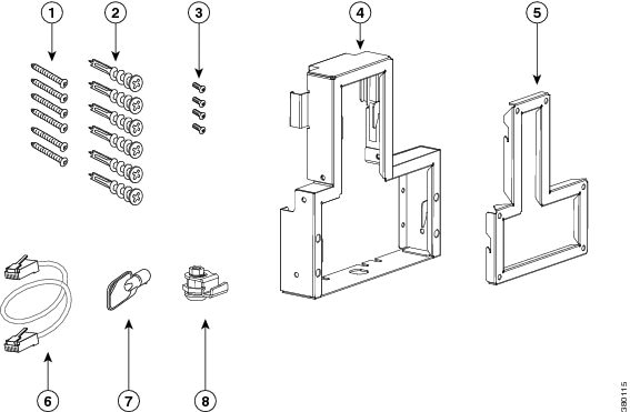
Wall-Mount Components


Note

The hardware that is included in this wall-mount kit is for drywall installation. For installation onto other surfaces, such as brick or concrete, you must provide your own hardware.


Figure 1. Wall-Mount Kit for Single-Phone Assembly
1 Six 8-18 x 1.25 inch Phillips-head screws 5 One wall bracket
2 Six anchors 6 One 6-inch Ethernet cable
3 Four 3 x 6mm machine screws 7 One lock-down key
4 One phone bracket 8 One lock

Install Wall-Mount

Procedure


Step 1

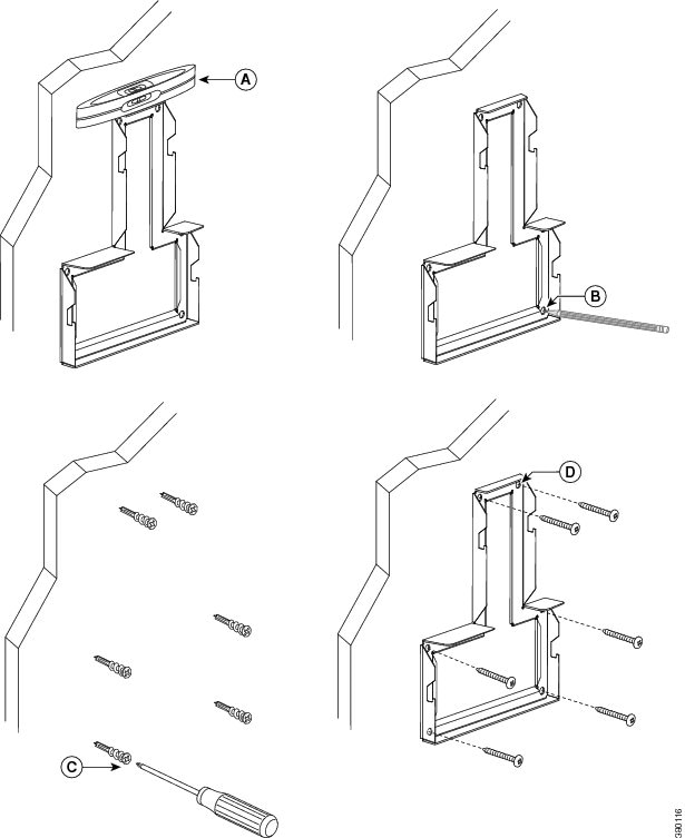
Attach the wall bracket in the desired location. You can install the bracket over an Ethernet jack, or you can run the Ethernet network cable to a nearby jack.

  1. Use the level to ensure that the bracket is level, then use a pencil to mark the screw holes.

  2. Carefully center the anchor over the pencil mark and use a no. 2 Phillips screwdriver to press the anchor into the wall.

  3. Screw the anchor clockwise into the wall until the anchor is seated flush.

  4. Use the included screws and a no. 2 Phillips screwdriver to attach the bracket to the wall.

    Figure 2. Attach Wall Bracket
Step 2

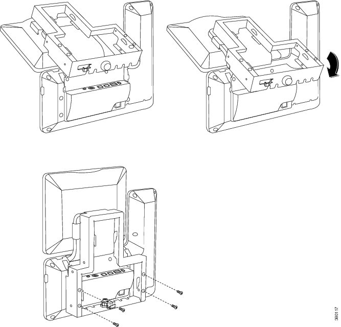
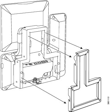
Attach the phone bracket to the device.

  1. Detach any attached cords from the base of the device.

  2. Slide the phone bracket onto the phone. Ensure that the device ports are accessible through the holes in the bracket.

  3. Use the machine screws to secure the phone bracket to the device.

  4. Reattach the cords and seat them in the clips that are incorporated into the device body.

    Figure 3. Attach Phone Bracket
Step 3

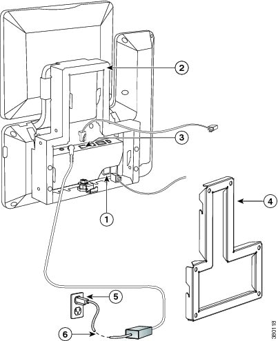
Attach the Ethernet cable to the 10/100/1000 SW network port and wall jack.

If you are connecting a network device (such as a computer) to the device, attach the cable to the 10/100/1000 computer (PC access) port.

If you are using an external power supply, plug the power cord into the device.

Figure 4. Attach Cables
1 Handset port 4 Wall bracket
2 Phone bracket 5 AC adapter port
3 Network port 6 Power cable
Step 4

To attach the device to the wall bracket, insert the tabs on the top of the phone bracket into the slots on the wall bracket. Ensure that the power cord and any other cable that does not terminate in the wall behind the bracket are positioned in one of the cable-access openings in the bottom of the bracket. The phone and wall bracket openings together form circular openings with room for one cable per opening.

Figure 5. Attach Device to Wall Bracket
Step 5

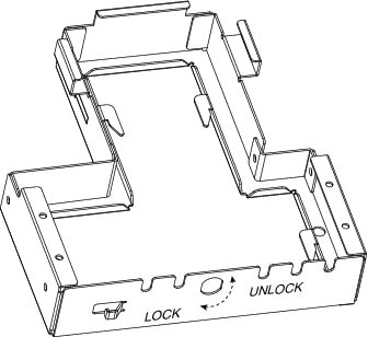
Use the lock-down key to lock the device to the wall bracket.

You can store the lock-down key on the key hook at the bottom of the phone bracket.

Figure 6. Phone Bracket with Key Hook