Packaged CCE Administration

Getting Started

Sign In

You must do post installation configurations to sign in to the Unified CCE Administration. For more information, see Post Installation Configuration .

Sign in to Unified CCE Administration at https://<IP Address>/cceadmin. <IP Address> is the address of the Side A or B Unified CCE AW or optional external HDS.


Note


Users are logged out of the Unified CCE Administration console automatically after 30 minutes of inactivity.


Administrators

Administrators sign in using their Active Directory credentials. For username, use the user@domain.com format.

Supervisors

Supervisors on an IPv6 network sign in to Unified CCE Administration at https://<FQDN>/cceadmin. <FQDN> is the fully qualified domain name of the Side A or B CCE AW or optional external HDS.

Supervisors sign in using their Active Directory (user@domain.com) or single sign-on credentials. If supervisors are enabled for single sign-on, after entering their username they are redirected to the Identity Provider sign-in screen to enter their credentials. Supervisors are redirected to Unified CCE Administration after successfully signing in.

Languages

If the Language Pack is installed, the Sign-In window includes a Language drop-down menu, showing more than a dozen languages. English is the initial and the default language. Select any other language to see the user interface and the online help in that language. The system retains your choice for subsequent sign-ins until you change it again.

Single Sign-On Log Out

For a complete logout from all applications, sign out of the applications and close the browser window. In a Windows desktop, log out of the Windows account. In a Mac desktop, quit the browser application.


Note


Users enabled for single sign-on are at risk of having their accounts misused by others if the browser is not closed completely. If the browser is left open, a different user can access the application from the browser page without entering credentials.


System Interface

Packaged CCE user interface enables you to configure the application through one window. The landing page has a left navigation bar and a card view which contains all the configuration options. What you see after a successful sign-in depends on your role.

The left navigation bar consists of the following menus:

  • Overview

  • Infrastructure

  • Organization

  • Users

  • Desktop

  • Capacity

The following menus appear as cards:

  • Infrastructure Settings

  • Call Settings

  • User Setup

  • Organization Setup

  • Bulk Import

  • Desktop Settings

  • Features

  • Email and Chat

    (Available only when ECE Web Server is added to the Infrastructure > Inventory page on the Unified CCE Administration.)

Note


The Unified CCE Administration interface also provides access to HTML-based online help for users and administrators. Click on the help button (?) on any page (except the Overview page) in the Unified CCE Administration interface and the online help specific to that page is displayed in a pop-over window. You can navigate to the previous or next page in the online help using the following keys:

  • MAC - Command + left arrow or Command + right arrow

  • Windows - Alt+ right arrow or Alt + left arrow


Lists

List Windows

Most tools open to a List window that has rows for all currently configured objects. For example, the Teams tool has a list with a row for each team, and the Call Types tool has a list with a row for each call type. List windows allow you to search, sort, edit, and delete from the list.

Permissions on List windows vary for administrators and supervisors and are noted in the topic for each tool.

Search a List

There is a Search field on the List window for most tools. The search interface is similar, with small variations, depending on the tool.

Search and Administrators

If you sign in as a global administrator, a search returns all objects.

If you sign in as a departmental administrator, a search returns all objects in the departments you administer, as well as all global objects (objects that are in no departments).

Basic Search

Some tools offer a basic search on the Name (or name-equivalent) and Description fields.

Enter all or part of either value to find matches. Clear the search by deleting text from the Search field.

Search for Tools with Department IDs

For objects that can be associated with a department, you can click the + icon to the right of the Search field to open a popup window, where you can:

  • Enter a name or description ( for call types and precision queues add id).

  • Select departments, with options for Globals and Departments, Globals only, or Departments only.

    Selecting Globals and Departments or Departments only enables an input field where you can enter a space-separated list of department names. (Departments is an OR search.)


    Note


    Search by department is enabled only when departments are configured.


Agent Advanced Search
The Search field in the Agents tool offers an advanced and flexible search.

Click the + icon at the far right of the Search field to open a popup window, where you can:

  • Select to search for agents only, supervisors only, or both.

  • Enter a username, agent ID, first or last name, or description to search for that string.

  • Enter one or more team names separated by spaces. (Team is an OR search--the agent or supervisor must be a member of one of the teams.)

  • Enter one or more attribute names separated by spaces. (Attributes is an AND search--the agent or supervisor must have all attributes.)

  • Enter one or more skill group names separated by spaces. (Skill Groups is an AND search.)

  • Select departments, with options for Globals and Departments, Globals only, or Departments only.

    Selecting Globals and Departments or Departments only enables an input field where you can enter a space-separated list of department names. (Departments is an OR search.)

Sort a List

If a column in a List window has an arrow icon in the column header, click the arrow to sort in ascending or descending order.

Add Objects

Click New in a List window to open an Add window where you can complete fields to create and save a new object.

Update Objects

To edit an object in a List window, click in the row for that object. This opens a window where you can make and save modifications. This table explains which fields are editable for each tool.

In the List window for the Agent tool, you can edit descriptions, desk settings, and teams for multiple agents at once (see Edit Description, Desk Settings, and Teams for Multiple Agents).

In the List window of the Dialed Number tool, you can edit the ringtone media file for multiple Dialed Numbers at once (see Add and Update Ringtone Media File for Multiple Dialed Numbers).


Remember


Not all tools are available for all Deployment Types.


Tool Editable Fields
Administrators All fields
Agents

All fields except Site and Peripheral Set.

If an agent is not enabled for single sign-on, you can check Change Password to reset the agent's password.

Note

 
  • When you change the team association for an agent record in Packaged CCE, the same change is updated in the corresponding collection in Unified Intelligence Center.

  • When you change the username for a supervisor's record in Packaged CCE, the same is updated in the corresponding user account in Unified Intelligence Center.

  • For an existing supervisor's record, if you uncheck the Is Supervisor check box, the corresponding user account is deleted from Unified Intelligence Center.

Attributes

All fields except Type.

Bucket Intervals

Name

You cannot edit the built-in bucket interval.

Bulk Jobs No fields
Business Hours

General tab: All fields.

Regular Hours tab: All fields.

Special Hours & Holidays tab: All fields.

Status Reasons: The Status Reason field is editable.

Call Types

All fields except the system-generated ID.

Campaigns

General tab: All fields except Type field.

Skill Group tab: You can add and delete the Skill Groups using Add and Delete buttons.

Advanced tab: All fields.

Desk Settings All fields
Dialed Numbers All fields except Site, Routing Type , Peripheral Setand Media Routing Domain.
Expanded Call Variables

For user-defined array and scalar expanded call variables, Name, Description, Maximum Length, Enabled, and Persistent are editable.

For built-in expanded call variables, Enabled and Persistent are the only editable fields.

Media Routing Domains

All fields

You cannot edit the built-in Cisco_Voice MRD or Multichannel MRDs for Enterprise Chat and Email.

Network VRU Scripts All fields
Precision Queues All fields

Reason Labels

Label, Description , Global , and Team Specific
Roles

For custom roles, except for the Administrators, Departments and Roles fields in the Access category, all fields on both tabs are editable.

You cannot edit the built-in roles.

Routing Pattern

All fields except Routing Pattern, Site and Pattern Type.

Location

All fields except Location Name.

SIP Server Group

All fields except Domain Name FQDN, Site, and Type.

Teams All fields except Site and Peripheral Set.

Note


When you update an existing team record in Packaged CCE, the same changes are also updated in the corresponding collection in Unified Intelligence Center.

Skill Groups

All fields except Site, Media Routing Domain , Peripheral Set and Peripheral Number.

Note


The Peripheral Number field is generated automatically when you add and save a new skill group. It shows the number of the skill group, as known on the peripheral.

Delete Objects

To delete an object from a List window, hover over the row for that object to see the x icon at the end of the row. Click the x icon and confirm your intention to delete.

Departmental administrators cannot delete global objects. Objects are identified as global in the Department column in the List window.

When you delete an object from Unified CCE Administration, the system does one of the following:

  • Immediately deletes the object.

  • Marks the object for deletion and enables permanent deletion. (You delete the object permanently using the Deleted Objects tool in Configuration Manager.)

  • Shows an error message explaining why the object cannot be deleted in its current state.

You cannot delete certain objects, including:

  • Objects set as system defaults, such as the default desk settings.

  • Objects referenced by other objects, such as a call type that is referenced by a dialed number.

  • Most built-in objects, such as built-in expanded call variables.

This table lists the delete types for all Unified CCE Administration objects. Available objects depend on your role and deployment type.

Tool Delete Type Notes
Administrators Permanent
Agents Marked

Note


When you delete an agent for which Is Supervisor check box is selected, the corresponding user account in Unified Intelligence Center is also deleted.

When you delete an agent, the association with team is also removed and same is updated in the corresponding collection in Unified Intelligence Center.

Attributes Marked
Bucket Intervals Marked
Bulk Jobs Permanent

Deletes the bulk job, its content file, and its log file from the host computer that created it.

You can delete a bulk job that is in queue, has completed, or has failed.

You cannot delete a bulk job that is in process.

If your deployment includes two AW server hosts, you must delete a bulk job from the Unified CCE AW host on which it was created.

Business Hours

Permanent

You cannot delete a business hour associated with a script. You must first dissociate the business hour from the script.

Status Reasons

Permanent

Call Types Marked
Campaigns Marked
Desk Settings Permanent
Dialed Numbers Marked

SIP Server Group

Permanent

You cannot delete the SIP Server Group associated with a Routing Pattern. You must first remove the SIP Server Group from the Routing Pattern.
Expanded Call Variables Marked
Media Routing Domains Permanent

You cannot delete the built-in Cisco_Voice MRD or Multichannel MRDs for Enterprise Chat and Email (ECE).

Network VRU Scripts Permanent

File Transfer Job

Permanent

Deletes the file transfer job, its job details file, and its log file from the host computer where it is created.

You cannot delete a file transfer job that is in processing state.

Precision Queues Marked Depends on whether the precision queue is referenced statically or dynamically in a script. .
Reason Labels Marked
Roles Permanent
Routing Pattern Permanent
Location Permanent
Teams Permanent

Note

 
When you delete a team in Packaged CCE, the corresponding collection is also deleted in Unified Intelligence Center.
Skill Groups Marked

Popup Windows

Popup window selection

Many Add and Edit windows have popup windows for searching and choosing objects that are relevant to that tool.

Some popup windows allow you to chose one object. Other popup windows allow you to select multiple objects. For example, because an agent can be on only one team, the popup window for adding an agent to a team allows only one selection, while the Skill Group Members popup window allows you to select one or more agents to add to the skill group.

Click the + icon to open the popup window, where you can locate and select items that are configured.

Keyboard Shortcuts

Press the question mark (?) key to open a window that shows the keyboard shortcuts that are applicable for that tool and for your status (Supervisor or Administrator).


Tip


The keyboard shortcuts window does not open when you press the (?) key in a text field. Press the esc key to remove focus from the text field and then press the (?) key.


System and Device Sync Alerts

Unified CCE Administration includes icons to notify users of any system alerts and device out-of-sync alert.

System Alerts

In Unified CCE Administration, you can monitor the status of the systems. The Alerts icon on the page includes alert count.

To view the alert and validation rule of a machine, click the Alerts icon. The Inventory page opens where you can view more details on the errors. For more information on server status rules, see Monitor Server Status Rules for Packaged CCE 2000 Agents Deployment

Device Out of Sync Alerts

In Unified CCE Administration, the configured data is synchronized with respective devices deployed in the inventory. If configured data synchronization fails with any device, the device is marked as out-of-sync and the Out of Sync device alert icon appears at the top of the page.

You can click the icon to open the Inventory page, and view data synchronization status of:

  • Cisco Unified Customer Voice Portal (CVP)

  • Cisco Finesse Primary

  • Cisco Unified Intelligence Center (CUIC) Publisher

  • Enterprise Email and Chat (ECE) Web Server

  • Cisco Virtualized Voice Browser (VVB) and

  • Cloud Connect Publisher

You can perform manual synchronization of data on each In Sync and Out of Sync device in the Inventory. See Manual Synchronization of Configured Data.

Manual Synchronization of Configured Data
This procedure explains how to manually synchronize configured data. You can do a Full Sync (for CVP and VVB) or a Differential sync.

Full Sync: This option is enabled for all CVPs (Main site and remote site) and VVBs (Main site and remote site).

Full Sync does the following:
  • CVP: reinitializes the device (CVP redeploy) and synchronizes all configuration data from the time when the initial configuration was done. Use this option after you reimage or reinstall the CVP Server.

  • VVB: synchronizes all configuration data from the time when the initial configuration was done. Use this option after you reimage, reinstall, or readd the VVB Server.

  • Cloud Connect: synchronizes all configuration data from the time when the initial configuration was done. Use this option after you reimage, reinstall, or read the Cloud Connect Publisher.

Differential Sync: This option synchronizes the configured data from the time the device was out of sync.

Procedure

Step 1

Navigate to Unified CCE Administration > Overview > Infrastructure Settings > Inventory.

Step 2

If the device Sync Status is In Sync, click the Sync icon and select Full Sync.

Step 3

If the device Sync Status is Out of Sync, click the Sync icon and select one of the following options

  • Differential Sync

  • Full Sync

Step 4

Click the Sync button.

Note


If the Full Sync operation is successful, you must restart the CVP device.


Smart License

Overview

Cisco Smart Software Licensing is a flexible software licensing model that streamlines the way you activate and manage Cisco software licenses across your organization. Smart Licenses provide greater insight into software license ownership and consumption, so that you know what you own and how the licenses are being used. The solution allows you to easily track the status of your license and software usage trends. It pools the license entitlements in a single account and allows you to move licenses freely across virtual accounts. Smart Licensing is enabled across most of the Cisco products and managed by a direct cloud-based or mediated deployment model.

Smart Licensing registers the Product Instance, reports license usage, and obtains the necessary authorization from Cisco Smart Software Manager (Cisco SSM) or Cisco Smart Software Manager On-Prem (Cisco SSM on-Prem).

You can use Smart Licensing to:

  • View license usage and count.

  • View the status of each license type and the product instance.

  • View the product licenses available on Cisco SSM or Cisco SSM on-Prem.

  • Register or deregister the Product Instance, renew license authorization and license registration.

  • Sign in additional agents to Unified CCX up to the maximum limit that is configured in your OVA.

Smart Licensing Capabilities

Smart Licensing works in conjunction with Cisco Smart Software Manager (Cisco SSM) to intelligently manage product licenses by providing real-time visibility of license status and usage. You can use this data to make better purchase decisions, based on your consumption. Smart Licensing establishes a pool of software licenses or entitlements in Cisco Smart Account.

The Smart Account provides a central location where you can view, store, and manage your licenses, across the organization. You can get access to your software licenses, hardware, and subscriptions through your Smart Account. Smart Accounts are required to access and manage Smart License-enabled products.

Creating a Smart Account is easy and takes less than five minutes. Create a Smart Account on software.cisco.com.

Prerequisites for Smart Licensing

The following are the prerequisites for configuring Smart Licensing:

  • Smart Licensing Enrollment

    Set up Smart and Virtual accounts. For more information, see https://software.cisco.com/#module/SmartLicensing.

  • Adoption of License Integration Strategy

    Decide how you want to connect your product instance to Smart Licensing servers:

    For more information, see Smart License Deployments.

  • Import the Rogger A certificate into the AW machines

    1. Export Logger/Rogger A certificate and save it by using the url https:<Logger/Roggerhostname>:443

    2. Import the certificate in AW by using the following command:

      • cd %CCE_JAVA_HOME%\bin
      C:\Program Files (x86)\Java\jre1.8.0_221\bin>keytool.exe -keystore 
      Program Files (x86)\Java\jre1.8.0_221\lib\security\cacerts" 
      -import -alias <alias name> -file <certicate with fully qualified path>
    3. Enter the truststore password when prompted.

    4. Enter 'Yes' when prompted to trust the certificate.

    5. Restart the Tomcat service.

Smart License Deployments

There are two software deployment options for Smart Licensing:
  • Direct - Cisco Smart Software Manager (Cisco SSM)

  • Cisco Smart Software Manager On-Prem (Cisco SSM On-Prem)

Direct - Cisco Smart Software Manager (Cisco SSM)

The Cisco SSM is a cloud-based service that handles your system licensing. The Product Instance can connect either directly to Cisco SSM or through a proxy server.

Cisco SSM allows you to:

  • Create, manage, or view virtual accounts.

  • Manage and track the licenses.

  • Move licenses across the virtual accounts.

  • Create and manage Product Instance Registration Tokens.

For more information about Cisco SSM, go to https://software.cisco.com.

Cisco Smart Software Manager On-Prem (Cisco SSM On-Prem)

Cisco SSM On-Prem is an on-premises component that can handle your licensing needs. When you choose this option, Packaged CCE registers and reports license consumption to the Cisco SSM On-Prem, which synchronizes its database regularly with Cisco SSM that is hosted on cisco.com.

You can use the Cisco SSM On-Prem in either Connected or Disconnected mode, depending on whether the Cisco SSM On-Prem can connect directly to cisco.com.

Configure Transport URL for Cisco SSM On-Prem with Smart Call-Home URL: https://<OnpremCSSM>/Transportgateway/services/DeviceRequestHandler


Note


The <OnpremCSSM> value must match with the SSM Tomcat Certificate Common Name or Subject Alternative Name. In the above URL, replace <OnpremCSSM> with FQDN or IP, based on the SSM Tomcat Certificate.


  • Connected—Use when there is connectivity to cisco.com directly from the Cisco SSM On-Prem. Smart account synchronization occurs automatically.

  • Disconnected—Use when there is no connectivity to cisco.com from the Cisco SSM On-Prem. Cisco SSM On-Prem must synchronize with Cisco SSM manually to reflect the latest license entitlements.

    For more information on Cisco SSM On-Prem, see https://www.cisco.com/c/en/us/buy/smart-accounts/software-manager.html.

Smart Licensing Task Flow

Complete these tasks to set up smart licensing for Packaged CCE.

Steps

Action

Description

Step 1

Create your Smart Account

Use the Smart Account to organize licenses according to your needs. To create a Smart Account, go to http://software.cisco.com

After the Smart Account is created, Cisco SSM creates a default Virtual Account for this Smart Account. You can use the default account or create other Virtual Accounts.

Step 2

Obtain the Product Instance Registration Token

Generate a product instance registration token for your virtual account.

For more information, see Obtain the Product Instance Registration Token.

Step 3

Configure Transport Settings for Smart Licensing

Configure the transport settings through which Packaged CCE connects to the Cisco SSM or Cisco SSM On-Prem.

For more information, see Configure Transport Settings for Smart Licensing.

Step 4

Select the License Type

Select the License Type before registering the product instance.

For more information, see License Types.

Step 5

Register with Cisco SSM

You can register Packaged CCE with Cisco SSM or Cisco SSM On-Prem.

For more information, see Register with Cisco Smart Software Manager.


Note


After performing the above steps, wait for 10-15 minutes for the correct status to get reflected in the UI. There is no need to restart the services.


Obtain the Product Instance Registration Token

Obtain the product instance registration token from Cisco SSM or Cisco SSM On-Prem to register the product instance. Generate the registration token with or without enabling the Export-Controlled functionality.


Note


The Allow export-controlled functionality on the products that are registered with this token check box does not appear for Smart Accounts that are not permitted to use the Export-Controlled functionality.


Procedure

Step 1

Log in to your smart account in either Cisco SSM or Cisco SSM On-Prem.

Step 2

Navigate to the virtual account with which you want to associate the product instance.

Step 3

Generate the Product Instance Registration Token.

Note

 
  • Select the Allow export-controlled functionality on the products registered with this token check box to turn on the Export-Controlled functionality for a product instance you want in this smart account. When you select this check box and accept the terms, you enable higher levels of encryption for products that are registered with this registration token. By default, this check box is selected.

  • Use this option only if you are compliant with the Export-Controlled functionality.

Step 4

Copy the generated token. This token is required when registering Smart Licensing with Cisco SSM.


Configure transport settings for smart licensing

Configure the connection mode between Packaged CCE and Cisco SSM.

Procedure

Step 1

From Unified CCE Administration, navigate to Overview > Infrastructure Settings > License Management.

Step 2

Click Transport Settings to set the connection method.

Step 3

Select the connection method to Cisco SSM:

  • Direct - (Packaged CCE communicates directly with Cisco's licensing servers.)

    URL: "https://smartreceiver.cisco.com/licservice/license".

    This is the default option. The configured URL is displayed.

  • Licensing Transport URL - (for SSM On-Prem)—Enter the appropriate URL in the URL field.

  • HTTP/HTTPS Proxy-(Send data through an intermediate HTTP or HTTPS proxy.) Enter the appropriate Host Name and Port number in the respective fields.

    Note

     
    Proxy servers that require authentication aren’t supported for this connection method.

Step 4

Click Save to save the settings.


Select License Type

Smart Licensing offers two types of license—Flex and Perpetual and it also provides two different usage modes—Production and Non-Production.

  • Flex—Flex license is a recurring subscription of Standard and Premium license. These subscriptions are renewed periodically, for example 1, 3, or 5 years.

  • Perpetual—Perpetual license is a permanent and one-time payment license that offers a Premium license.

  • Production—Production mode is when the licenses are used on live systems to handle actual production traffic. Yes

  • Non-Production—Non-production mode is used for labs, testing and/or staging areas, and not for live systems handling actual end-consumer traffic.


Note


If you select the incorrect license type, the product instance is placed in the Out-of-Compliance state. If this issue is unresolved, the product instance is placed in the Enforcement state where the system operations are impacted.


Procedure

Step 1

From Unified CCE Administration, navigate to Overview > Infrastructure Settings > License Management.

Step 2

Click License Type.

The Select License Type page is displayed.

Step 3

Select the License Type and the Usage Mode corresponding to what you have purchased before registering the product instance.

The following table lists the license types and licenses offered as part of Unified CCE and Packaged CCE Smart Licensing:

License Type

Licenses

Flex Production

Unified CCE and Packaged CCE:

  • Standard Agent

  • Premium Agent

  • Dialer Ports

  • Server License

Perpetual Production

Unified CCE and Packaged CCE:

  • Premium Agent

  • Dialer Ports

  • Server License

ICM:

  • Regular Agent

  • Avaya PG

  • Third-party IVR licenses

  • Server License

Perpetual Non-Production

  • Regular Agent

  • Premium Agent

  • Dialer Ports

  • Server License

  • Avaya PG

Step 4

Click Save.


Register with Cisco Smart Software Manager

The product instance has 90 days of evaluation period, within which, the registration must be completed. Else, the product instance gets into the enforcement state.

Register your product instance with Cisco SSM or Cisco SSM On-Prem to exit the Evaluation or Enforcement state.


Note


After you register the product instance, you cannot change the license type. To change the license type, deregister the product instance.


Procedure

Step 1

In Unified CCE Administration, navigate to Overview > Infrastructure Settings > License Management.

Step 2

Click Register.

Note

 
  • Before you register the product instance, ensure to select the License Type and the communication mechanism in Transport Settings.

Step 3

In the Smart Software Licensing Product Registration dialog box, paste the product instance registration token that you generated from Cisco SSM or Cisco SSM On-Prem.

Step 4

Click Register to complete the registration process.

After registration, the Smart Licensing Status displays the following details.

Table 2. Smart Licensing Status

Smart License Status

Description

On Unsuccessful Registration

Registration Status

Unregistered

License Authorization Status

Evaluation

Export-Controlled Functionality

Not Allowed

On Successful Registration

Registration Status

Registered (Date and time of registration)

License Authorization Status

Authorized (Date and time of authorization)

Export-Controlled Functionality

Not Allowed

Smart Account

The name of the smart account

Virtual Account

The name of the virtual account

Product Instance Name

The name of the product instance

Serial Number

The serial number of the product instance

Entitlements are a set of privileges customers and partners receive when purchasing a Cisco service agreement. Using Smart Licensing, you can view the License consumption summary for the entitlements of different license types. The License consumption summary displays the License Name, Usage Count, and Status against each entitlement name.

You can update or purchase entitlements on the Cisco Commerce website. For more information, see https://apps.cisco.com/Commerce/.


Registration, Authorization, and Entitlement Status

Registration Status

This table explains the various product registration status for Smart Licensing in the Unified CCE Administration portal:

Table 3. Registration Status

Status

Description

Unregistered

Product is unregistered.

Registered

Product is registered. Registration is automatically renewed every six months.

Registration Expired

Product registration has expired because the ID Certificate issued by Cisco SSM is not renewed for more than 12 months.

Authorization Status

This table describes the possible product authorization status for Smart Licensing in the Unified CCE Administration portal:

Table 4. Authorization Status

Status

Description

Evaluation state

Product is not registered with Cisco.

Evaluation Expired

Product evaluation period has expired.

Authorized

Product is in authorized or in compliance state. Authorization is renewed every 30 days.

Authorization Expired

Product authorization has expired. This usually happens when the product has not communicated with Cisco for 90 days. It is in an overage period for 90 days before enforcing restrictions.

Out-of-Compliance

Product is in out-of-compliance state because of insufficient licenses. It is in an overage period for 90 days before enforcing restrictions.

Unauthorized

Product is unauthorized.

No License in Use

No Licenses are in use.

License Entitlement Status

This table describes the possible product instance license entitlement status for Smart Licensing in the Unified CCE Administration portal:

Table 5. License Entitlement Status

Status

Status Description

Authorization Expired

Product authorization has expired, when the product has not communicated with Cisco for 90 days.

Not Authorized

Product instance is not authorized.

Evaluation state

Product is not registered with Cisco.

Evaluation Expired

Product evaluation period has expired.

In Compliance

Product is in authorized or in compliance state. Authorization is renewed every 30 days.

ReservedInCompliance

Entitlement is in compliance with the installed reservation authorization code.

Out-of-Compliance

Product is in out-of-compliance state because of insufficient licenses. It is in an overage period for 90 days before enforcing restrictions.

Not Applicable

Entitlement is not applicable.

Invalid

Error condition state.

Invalid Tag

Entitlement tag is invalid.

No License in Use

Entitlement is not in use.

Waiting

Waiting for an entitlement request's response from Cisco SSM or Cisco SSM On-Prem.

Disabled

Product instance is deactivated or disabled.

Out-Of-Compliance and Enforcement Rules

Out-of-Compliance

The Product Instance reports license usage to Cisco SSM every 15 minutes. If your license consumption is more than the entitlements for four consecutive reporting intervals, the Product Instance is pushed to the Out-of-Compliance state. The Out-of-Compliance period is for 90 days, within which you need to purchase the additional licenses. If you fail to take corrective action within the 90 days period, the Product Instance is pushed to the Enforcement state.

All CVPs in a virtual account share the licenses from a pool. If the license consumption exceeds than those available in the pool, all CVPs in the virtual account follow the Out-of-Compliance and Enforcement rules.

Enforcement

The Product Instance is in the Enforcement state in the following scenarios:

  • Out-of-Compliance expiry: When the Out-of-Compliance period of 90 days has expired.

    Purchase new licenses to exit the Enforcement state.

  • Authorization expiry: When the Product Instance has not communicated with Cisco SSM or Cisco SSM On-Prem for 90 days and has not automatically renewed the entitlement authorizations.

    Renew the license authorizations to exit the authorization expiry state.

  • Evaluation expiry: When the license evaluation period of 90 days has expired and the Product Instance is not registered with Cisco SSM.

    Register the Product Instance with Cisco SSM to exit the Evaluation expiry state.

License States

Smart Licensing has the following states:

  • Registration State

    • Unregistered—Product Instance is unregistered.

    • Registered—After you purchase the license, you need to register the Product Instance with Cisco SSM. To register with Cisco SSM, generate a registration token from the Cisco SSM portal. Use the registration token to register your Product Instance.

    • Registration Expired—Product Instance registration has expired because the ID Certificate issued by Cisco SSM is not renewed for more than 12 months. Reregister the Product Instance.

  • Authorization State

    • No licenses in use

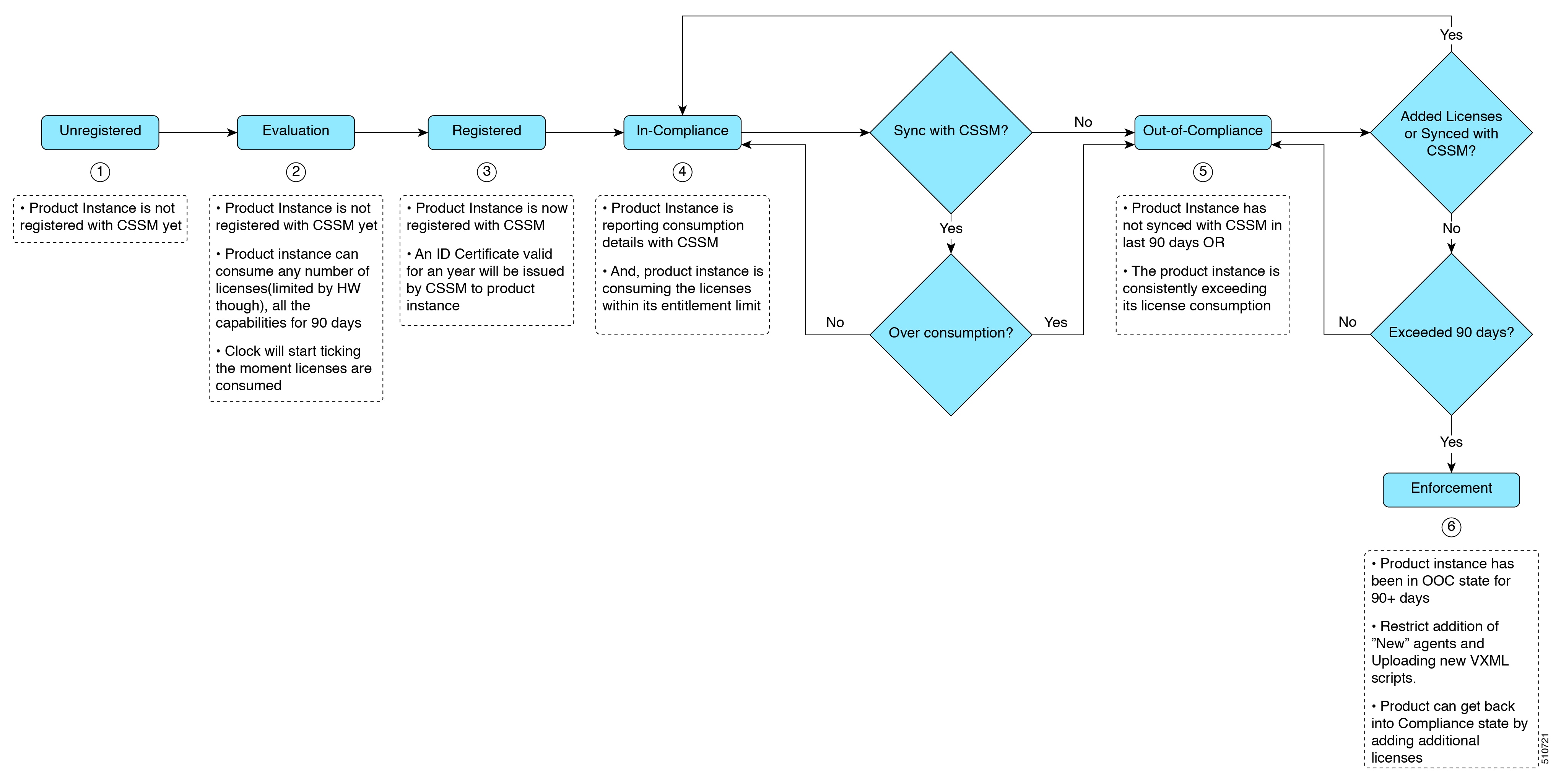
    • Evaluation Mode—The Product Instance license has an Evaluation period of 90 days. In the Evaluation period you have unlimited access to the product with highest set of product capabilities and unlimited number of licenses. You must register the system with Cisco SSM or Cisco SSM On-Prem within 90 days. If the system is not registered before the end of the evaluation period, it will be moved to the Enforcement state where certain system functions are restricted.

    • In Compliance—When the license consumption is as per the purchased quantity, the product is compliant.

    • Evaluation expired—Product Instance evaluation period has expired.

    • Authorized—Product Instance is in authorized or in compliance state. Authorization is renewed every 30 days.

    • Out of Compliance—Product Instance reports license usage to Cisco SSM every 15 minutes. If your license consumption is more than the entitlements for five consecutive reporting intervals, the Product Instance is transitioned to the Out of Compliance state.

      The out-of-compliance period is for 90 days, within which you need to purchase the additional licenses. If you fail to take corrective action within the 90 days period, the Product Instance is transitioned to the Enforcement state.

    • Authorization Expired—Product Instance authorization has expired. This usually happens when the product has not communicated with Cisco SSM for more than 90 days. It is in an overage period for 90 days before restrictions are enforced.

  • Enforcement State

    When the 90 day period of Out-of-Compliance, Evaluation Period or Authorization period has expired, the Product Instance is moved to the Enforcement state in which system operations are impacted for Contact Center components. The Product Instance is in the Enforcement state in the following scenarios:

    • Out-of-Compliance expiry—When the out-of-compliance period of 90 days has expired.

      Purchase new licenses to exit the Enforcement state.

    • Authorization expiry—When the Product Instance has not communicated with Cisco SSM or Cisco SSM On-Prem for 90 days and has not automatically renewed the entitlement authorizations.

      Renew the license authorizations to exit the Authorization expiry state.

    • Evaluation expiry—When the license evaluation period of 90 days has expired and the Product Instance is not registered with Cisco SSM.

      Register the Product Instance with Cisco SSM to exit the evaluation expiry state.

A pictorial representation of different license states is as follows:

Figure 1. License States

Notifications and Alerts

The system maintains real-time status of license usage after Product Instances are registered and activated. Administrators are notified through alerts, event logs, and emails on the status of licenses in the Smart and Virtual Accounts. Pay attention to system alerts and banners to get regular information on compliance status and take necessary action.

Following are some of the notification methods:

  • Banner Notifications

  • System Alerts

Banner Notifications

  • The banner displays the aggregate license compliance status on the Unified CCE Administration portal. The banner is displayed only when any of the product instances in the deployment is in the Evaluation, Out-of-Compliance, or Enforcement state.

    The License Compliance report displays the license status of product instances in the deployment. The reporting hierarchy is Enforcement, Out-of-Compliance, and Evaluation. This means that if any of the product instances in the deployment is in the Enforcement state, the banner displays Enforcement state as the overall status. Click the Learn More option to view the consolidated License Compliance report.

  • When licenses are consumed in a Non-Production System, a banner message, "You are using a Non-Production System”, is displayed.

System Alerts

Smart Licensing related system alerts, which get auto-corrected, are displayed in Unified CCE Administration portal when:

  • Smart License state is not initialized

  • Smart Agent is not enabled

  • Serial number is not generated

In the above conditions, a red system alert is displayed in the Alerts button on the Unified CCE Administration portal. The red circle against the name of the machine in the inventory indicates the identified issue and the immediate action needed. After the issue is resolved, a green circle against the name of the machine indicates the system is running fine, for example, when the Smart Agent is enabled or Smart License state is initialized.

License Consumption Calculation

The system reports peak license usage to Cisco SSM every 15 minutes. If in five consecutive reports you are seen to have consumed more licenses than you are authorized to, the Product Instance is pushed to the Out-of-Compliance state. The Out-of-Compliance period is for 90 days, within which you need to purchase additional licenses. If you do not take corrective action within the 90 days period, the Product Instance is pushed to the Enforcement state in which, some of the operations are impacted.

Log in to Cisco SSM to view the detailed license consumption. Cisco SSM reports purchased quantity, in-use quantity, and balance licenses. At a quick glance, you can decide if the consumption of your licenses are in deficit or surplus, based on which you can make the right decision on the number of licenses that are required.

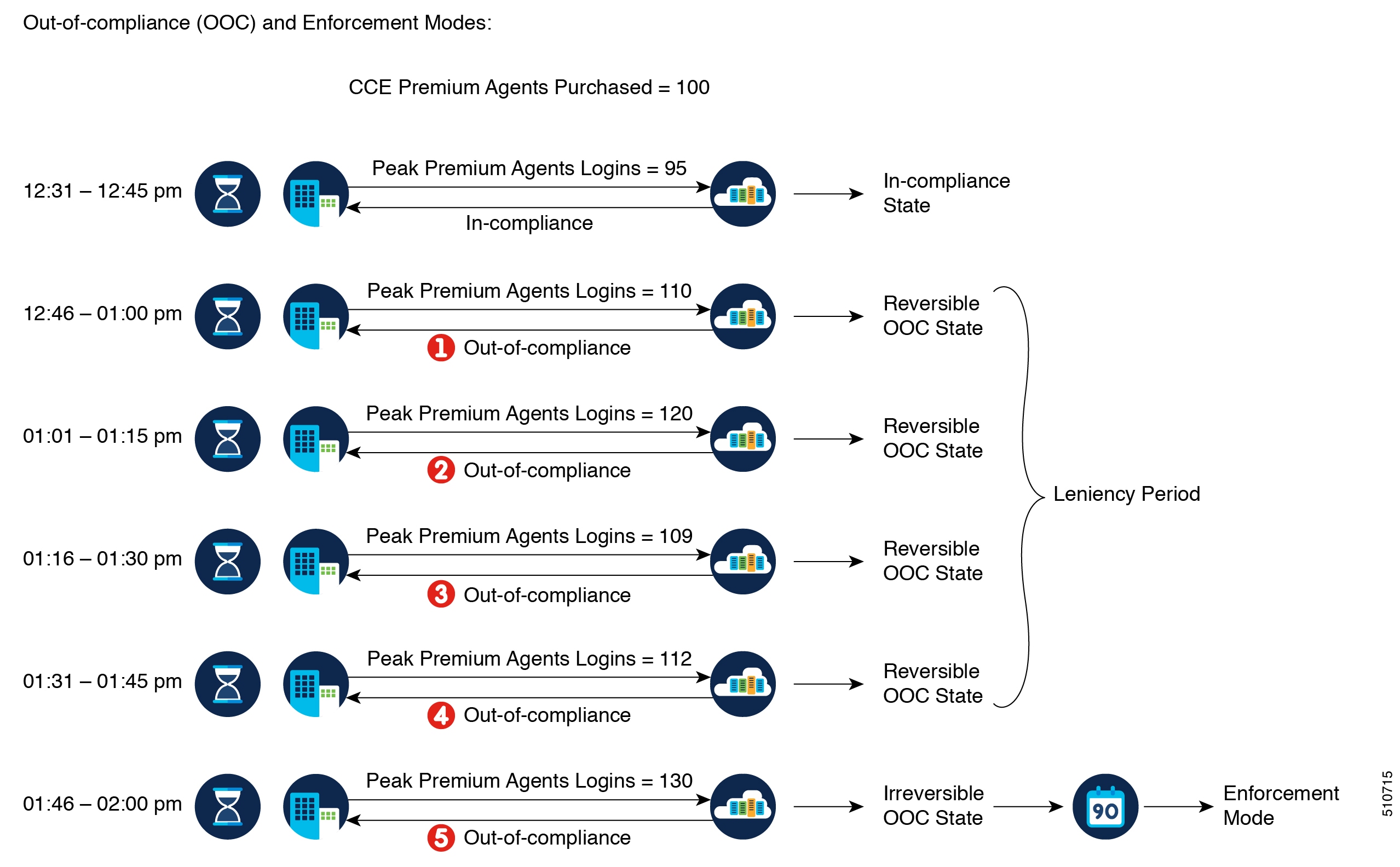
License Computation Scenario 1

License purchased: 100 licenses

Figure 2. License Computation

If Cisco SSM registers consecutive five instances of license over usage, the Product Instance transitions to Out-of-Compliance. Thereafter, the Product Instance reports Locked usage quantity (130 in the above scenario) until the deficit licenses (130-100=30) are purchased. The Locked usage is the highest number of license usage (130) in the Out-of-Compliance state. The Product Instance will not report the actual license usage when the Product Instance is in the Out-of-Compliance state.

Purchase additional licenses from the Cisco Commerce website (CCW) to exit the Out-of-Compliance state.

Reported Usage column in the License Management page displays the locked usage quantity. However, the actual license usage is available in the License Consumption report of CUIC.

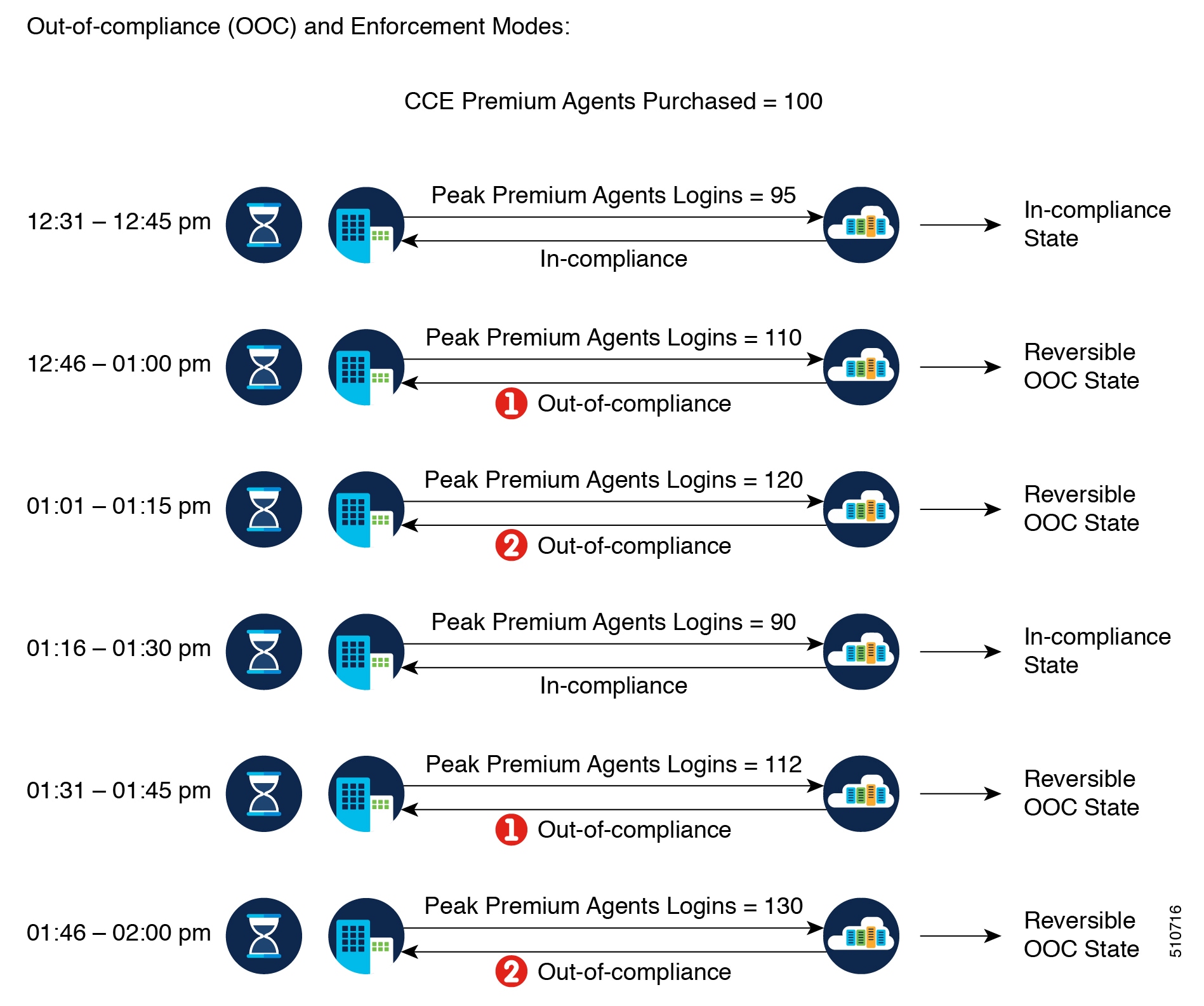
License Computation Scenario 2

If Cisco SSM reports only two consecutive instances of license over usage within a one-hour window, the Product Instance will not transition to Out-of-Compliance. For example:

License Purchased: 100 licenses

Figure 3. License Computation

In the example, the Product Instance is back to In-compliance state after two instances of overage. The next time the Product Instance goes Out-of-Compliance, the count will be 1 of 5. So, you get 45 min (after the first Out-of-Compliance notification from Cisco SSM) to bring back the consumption within the acceptable range to stay in the In-compliance state.


Note


To know about the agent license that is consumed by the Standard and Premium licenses, see the Cisco Collaboration Flex Plan Contact Center Data Sheet at https://www.cisco.com/c/en/us/products/collateral/unified-communications/cisco-collaboration-flex-plan/datasheet-c78-741220.html


New Deployments

For new deployments, buy the licenses on Cisco Commerce website at https://apps.cisco.com. Begin to use the product by using the licenses from your Smart Account.

Migrate to Smart Licensing

If you are upgrading to Unified CCE Release 12.5(1), from Unified CCE Release 10.x or above, use self serve capabilities in Cisco SSM to declare the licenses that you own.

PAK-Based Migration

Migrate to Smart Licensing for fulfilled, partially fulfilled, and unfulfilled PAKs.

  1. Log in to the Traditional Licensing Portal at https://tools.cisco.com/SWIFT/LicensingUI/Home.

  2. Locate the PAKs that are to be migrated.

  3. Right click and select Assign to Smart Account and Virtual Account.

  4. Select the Smart Account and Virtual Account to which the PAK will be assigned.

    Once done, the classic PAKs will show assigned Smart Account.

Using LRP
  1. Select the PAK that needs to be converted to smart entitlement.

  2. From the PAK context option, select Convert to Smart Licensing.

  3. Select the SKUs, Quantity to Convert and click on Submit.


    Note


    Classic Licenses that are partially converted will need new Classic License file for managing the remaining Classic Licenses.


    After the licenses are converted to smart entitlements, successful conversion message is shown. The entitlements will be available on Cisco SSM under selected Smart and Virtual Account.

Using Cisco SSM

Convert PAKs to equivalent Smart Licenses.

  1. Go to the Convert PAKs tab.

    Assigned PAKs are listed on the Cisco SSM portal.

  2. Click Convert to Smart License in the Actions column.

  3. Select SKUs and Quantity to Convert and click Next.

    Classic Licenses which are partially converted will need new Classic License file for managing the remaining Classic Licenses.

  4. Review and to confirm click Convert License.

    Once converted to Smart Entitlement, the old classic licenses will be invalidated. Converted Smart Licenses are added into the Smart Account and the Virtual Account.

Device-Based Conversion

Use the device-based Smart Licensing to convert the Classic licenses to smart entitlements.

Using LRP
  1. Login to the Traditional Licensing Portal at https://tools.cisco.com/SWIFT/LicensingUI/Home

  2. Go to Devices tab and then Add Device.

  3. Locate the device to be migrated (filter using the device UUID). Once added, the added device shows up under Devices tab.

  4. Select the device and right click Assign to Smart Account to Smart Account and Virtual Account.

  5. Select the Smart Account and the Virtual Account.

    Once done, the table is updated with the Smart Account assigned to the device.

  6. For Classic licenses to be converted to smart entitlements, select the device and select Convert licenses to Smart Licensing option.

  7. Select the SKUs and Quantity to Convert.

    Classic Licenses which are partially converted will need new Classic License file for managing the remaining Classic Licenses.

  8. Confirm and click Submit.

    Once the licenses are fully converted, the device UUID will be removed from the LRP. Once done, the successful conversion message is shown. The entitlements will now be available on Cisco SSM under selected Smart and Virtual Account.

Using Cisco SSM

Assigned Devices show up on the Cisco SSM Portal. The Cisco SSM portal is refreshed every hour. If the assigned device is not visible in Cisco SSM, please recheck after an hour.

  1. Go to Convert Licenses tab and click the License Conversion wizard.

  2. Select the Product family and provide the device UUID.

  3. Select the SKU and Quantity to Convert.

    Classic Licenses which are partially converted will need new License file for managing the remaining Classic Licenses.

  4. Review, Confirm and click Submit.

    When the conversion is complete and smart licenses are active, the classic licenses are invalidated.

License Management

Smart Licensing can be managed by using Cisco SSM and .

  • Cisco SSMCisco SSM enables you to manage all your Cisco smart software licenses from a centralized website. With Cisco SSM, you organize and view your licenses in groups called virtual accounts (collections of licenses and product instances).

    You can access Cisco SSM from https://software.cisco.com, by clicking the Smart Software Licensing link under the License menu.

  • License Management in Unified CCE Administration portalUsing the License Management option in the Unified CCE Administration portal, you can register or deregister the product instance, select your License Type, set transport settings or view the licensing consumption summary.

Smart Licensing Tasks

After you successfully register Smart Licensing, you can perform the following tasks as per the requirement:

  • Renew Authorization—The license authorization is renewed automatically every 30 days. Use this option to manually renew the authorization.

  • Renew Registration—The initial registration is valid for one year. Registration is automatically renewed every six months. Use this option to manually renew the registration.

  • Reregister—Use this option to forcefully register the product instance again.

  • Deregister—Use this option to release all the licenses from the current virtual account.

Renew Authorization and Renew Registration are automated tasks that take place at regular intervals. If there is a failure in the automated process, you can manually renew authorization and registration.


Note


You have to Deregister and Reregister manually.


Renew Authorization

The license authorization is renewed automatically every 30 days. The authorization status expires after 90 days if the product is not connected to Cisco SSM or Cisco SSM On-Prem.

Use this procedure to manually renew the License Authorization Status for all the licenses listed in the License Type.

Procedure

Step 1

In Unified CCE Administration, navigate to Overview > Infrastructure Settings > License Management.

Step 2

Click Action > Renew Authorization.

This process takes a few seconds to renew the authorization and close the window.


Renew Registration

Use this procedure to manually renew your certificates.

The initial registration is valid for one year. Renewal of registration is automatically done every six months, provided the product is connected to Cisco SSM or Cisco SSM On-Prem.

Procedure

Step 1

In Unified CCE Administration, navigate to Overview > Infrastructure Settings > License Management .

Step 2

Click Action > Renew Registration.

This process takes a few seconds to renew the authorization and close the window.


Reregister License

Use this procedure to reregister Packaged CCE with Cisco SSM or Cisco SSM On-Prem.

Note


Product can migrate to a different virtual account when reregistering with the token from a new virtual account.


Procedure

Step 1

In Unified CCE Administration, navigate to Overview > Infrastructure Settings > License Management.

Step 2

Click Action > Reregister.

Step 3

In the Smart Software Licensing Product Registration dialog box, paste the copied or saved Registration Token Key that you generated using the Cisco SSM or Cisco SSM On-Prem in the Product Instance Registration Token text box.

Step 4

Click Reregister to complete the reregistration process.

Step 5

Close the window.


Deregister License

Use this procedure to deregister Packaged CCE from Cisco SSM or Cisco SSM on-Prem and release all the licenses from the current virtual account. All license entitlements that are used for the product are released to the virtual account and is available for other product instances to use.

Note


If Packaged CCE is unable to connect to Cisco SSM or Cisco SSM on-Prem, and the product is deregistered, then a confirmation message notifies you to remove the product manually from Cisco SSM or Cisco SSM on-Prem to free up licenses.


Note


After deregistering, the product reverts to the Evaluation state if the evaluation period is not expired. All the license entitlements that are used for the product are immediately released to the virtual account and are available for other product instances to use it.


Procedure

Step 1

In Unified CCE Administration, navigate to Overview > Infrastructure Settings > License Management .

Step 2

Click Action > Deregister.

Step 3

On the Confirm Deregistration dialog box, click Yes to deregister.


Best Practices

Some of the best practices for Smart Licensing are:

  • Before purchasing your licenses, run the License Consumption report on the existing system to understand the consumption pattern to make the right purchase decisions on the license requirement.

  • Configure Admin email address in Cisco SSM to receive notifications and alerts from Cisco SSM.

Infrastructure Settings

Inventory Management

Inventory update can be done in the following scenarios:

  • When you rebuild Virtual Machines (VMs), you can update the IP address or hostname of these machines in the inventory.

  • When you move your existing VMs to another data center, you can update the IP address or hostname of these machines in the inventory.

For more information, see:

Manage Devices

You can configure any of the following components:

  • CVP Server

  • CVP Reporting Server

  • VVB

  • Finesse

  • Identity Service

The term device refers to a configurable application or platform. More than one device can reside on a server. For example, one physical server can contain a CVP Server and a Reporting Server. In this case, each device is configured with the same IP address.

CVP Server Services Setup

As part of Packaged CCE fresh install, the CVP Server is added with default configuration values. You can configure:

  • ICM Service

  • SIP Service

  • IVR Service

  • VXML Server

  • Infrastructure


Important


Except for the configurations that require a Call Server restart, configure all the other CVP Server configurations during off-peak hours (not during heavy call load).


For shutting down services of call server/reporting server, see Graceful Shutdown of Call Server or Reporting Server.

Set Up ICM Service

The ICM Service enables communication between Unified CVP components and the ICM Server. It sends and receives messages on behalf of the SIP Service, the IVR Service, and the VXML Service. You install the ICM Service with the CVP Server.

You must configure the ICM Service if you add or edit a CVP Server and use any of these call flow models:

  • Call Director

  • VRU-Only

  • Comprehensive

Procedure

Step 1

Navigate to Unified CCE Administration > Overview > Infrastructure Settings > Device Configuration > CVP Server.

Step 2

Choose the site name for the ICM Service. By default, it is Main.

Step 3

Complete the following fields:

Table 6. ICM Service Configuration Settings

Field

Required?

Description

VRU Connection Port

yes

The port number on which the ICM Service 5000 listens for a TCP connection from the ICM PIM.

Default is 5000.

Maximum Length of DNIS

yes

The maximum length of an incoming Dialed Number Identification Service (DNIS). Range is 1 - 99999 characters.

Look for this information in your network dial plan. For example, if the gateway dial pattern is 1800******, the value of Maximum Length of DNIS must be 10.

The number of DNIS digits from the PSTN must be less than or equal to the maximum length of the DNIS field.

Note

 
If you use the Correlation ID method in your ICM script to transfer calls to Unified CVP, the maximum length of DNIS must be the length of the label that is returned from the ICM for the VRU leg of the call. When the ICM transfers the call, the Correlation ID is appended to the label. Unified CVP then separates the two, assuming that any digits greater than the maximum length of DNIS are the Correlation ID. The Correlation ID and the label are then passed to the ICM.

Enable secure communication with VRU PIM

-

Enables secure communication between ICM and the Unified CVP Server.

Trunk Utilization

Enable Gateway Trunk Reporting

-

Enables the gateway trunk reporting.

Maximum Gateway Ports

no

The value used for setting the maximum number of ports that a gateway supports in a CVP deployment. This is used to calculate the number of ports to report to the Unified ICM Server for each gateway.

Default is 700.

Monitored Gateways

no

The list of gateways available for trunk reporting.

Click + (Add) to add a new gateway.

Step 4

Click Save.


Set Up IVR Service

You must configure the IVR Service if you add a new Unified CVP Server or edit a Unified CVP Server in any of these call flow models:

  • Call Director, using SIP protocol

  • VRU-Only

  • Comprehensive, using SIP protocol

The IVR Service creates VXML documents that implement the Micro-Applications based on Run Script instructions received by the ICM. The VXML pages are sent to the VXML Gateway to be run. The IVR Service can also generate external VXML through the Micro-Applications to engage the Unified CVP VXML Server to generate the VXML documents.

The IVR Service plays a significant role in implementing a failover mechanism: those capabilities that can be achieved without ASR/TTS Servers, and VXML Servers. Up to two of each such servers are supported, and the IVR Service orchestrates retries and failover between them.

Before you begin
Configure the following servers before setting up the IVR Service:
  • ICM Server

  • Media Server

  • ASR/TTS Server

  • Unified CVP VXML Server

  • Gateway

Procedure

Step 1

Navigate to Unified CCE Administration > Overview > Infrastructure Settings > Device Configuration > CVP Server.

Step 2

Click the IVR tab. Complete the following fields:

Table 7. IVR Service Configuration Settings

Field

Required?

Description

Use Security for Media Fetches

-

If you select No (default), the HTTP URLs are generated to the Media Servers.

Note


The default setting is only applicable if the client is SIP Service and the Media Server is not set to a URL that explicitly specifies an HTTP/HTTPS scheme.

Select Yes to generate the HTTPS URLs to the Media Servers.

Use Backup Media/VXML Servers

-

If you select Yes (default) and a Media Server is unavailable, the gateway attempts to connect to the backup Media Server.

Use Host Names for Default Media/VXML Servers

-

By default, the IP address is used for the VXML Server and the Media Server. If you enables this field, the hostnames are used rather than the IP addresses.

Note


When you enable this field, enable the High Availability(HA) for Media Server in each CVP Server in the site after you save the configuration.

To enable HA for Media Server, open the mediaServer.properties file in the C:\Cisco\CVP\conf folder and configure the following:

  • MediaServer.1.hostName = <Media Server Host>

  • MediaServer.1.ip = <Media Server IP>

The IP and hostname must match the default media server IP and hostname in the Unified CCE Administration. Define the corresponding <hostname>-backup entry to backup Media Server IP in VXML Gateway and Virtualized Voice Browser(VVB). When the primary host name fails, the media files fetch request can be served from backup media server.

Call Timeout

yes

The number of seconds the IVR Service waits for a response from the SIP Service before timing out. This setting must be longer than the longest prompt, transfer, or digit collection at a Voice Browser. If the timeout is reached, the call is canceled but no other calls are affected. The only downside to making the number arbitrarily large is that if calls are being stranded, they are not removed from the IVR Service until this timeout is reached.

Minimum is 6 seconds. Default is 7200 seconds.

Default Media Server

no

From the Default Media Server drop-down list, choose the default media server.

Step 3

Click Save.


Set Up SIP Service

You must set up the SIP Service if you add a new CVP Server in of these call flow models:

  • Call Director

  • Comprehensive

Session Initiation Protocol (SIP), RFC 3261, is the primary call control protocol in Unified CVP. The SIP Service uses SIP to communicate with other Unified CVP solution components, such as the SIP Proxy Server, the VXML and Ingress Gateways, and Cisco Unified Communications Manager SIP trunks and SIP phones.

Procedure

Step 1

Navigate to Unified CCE Administration > Overview > Infrastructure Settings > Device Configuration > CVP Server.

Step 2

Click the SIP tab. Complete the following fields:

Table 8. SIP Service Settings

Field

Required?

Description

Enable Outbound Proxy

-

Select Yes to use a Cisco Unified SIP proxy server.

Default is No.

Outbound Proxy Host

no

Select Enable Outbound Proxy to view the Outbound Proxy Host drop-down list. It displays a list of external SIP Server Groups.

Outbound Proxy Port

no

Default is 5060.

DNS SRV

Enable DNS SRV Type Query

-

Select Yes to use DNS SRV for outbound proxy lookup.

Note


If you enable Resolve SRV records locally, you must select Yes to ensure the feature works properly.

Resolve DNS SRV Locally

-

Select to resolve the SRV domain name with a local configuration file instead of a DNS Server.

Note


If you enable Resolve SRV records locally, you must select Yes to use the DNS SRV type query. Otherwise, this feature will not work.

Outgoing Transport Type

no

Specifies the outgoing transport. You can set it to TCP or UDP.

Default is TCP.

Port Number for Incoming SIP Requests

yes

Specifies the port to be used for incoming SIP requests.

Default is 5060.

Prepend Digits

no

Specifies the number of digits to be removed for SIP URI user number. Default is 0.

Use Error Refer

no

Flags for play error tone when a call fails to caller.

Default is False.

SIP Info Tone Duration

yes

Specifies the wait time in milliseconds for the SIP info tone. It is an optional value for the list addition.

Default is 100.

SIP Info Comma Duration

yes

Specifies the wait time in milliseconds for the SIP info comma. It is an optional value for the list addition.

Default is 100.

SIP Header Passing to ICM

Header Name

no

Specifies the SIP header name. Click + (Add) to add a new SIP header to be passed to ICM. It can support up to 255 characters.

Parameter

no

This field is optional for list addition. It can support up to 255 characters.

Security Properties

Incoming Secure Port

no

Specifies the port to be used.

Default is 5061.

Supported TLS Version

yes

Allows you to select the TLS versions supported for securing the SIP signaling on the IVR leg. The TLS versions currently supported are TLSv1.0, TLSv1.1, and TLSv1.2. Default is TLSv1.2.

Note


When you select a given TLS version, Unified CVP supports the SIP TLS requests for that version and the higher supported versions.

Supported Ciphers

no

This field defines the ciphers, which is supported by Unified CVP, with key size lesser than or equal to 2048 bits.

The default cipher is TLS_RSA_WITH_AES_128_CBC_SHA, which is prepopulated and cannot be deleted as it is mandatory for TLSv1.2.

Cipher configuration is available only if TLS is enabled.

Click + (Add) to add a new cipher.

Note


After you add the required ciphers restart the system for more information, refer to the topic Generate CVP ECDSA Certificate with OpenSSL at https://www.cisco.com/c/en/us/support/customer-collaboration/unified-customer-voice-portal/products-installation-and-configuration-guides-list.html

Note


The dialed number uses default values to play the ringtone and the error tone. These values cannot be edited.

Step 3

Click Save.


Set Up VXML Server

From the Unified CVP VXML Server Configuration tab, you can enable the reporting of Unified CVP VXML Server and call activities to the Reporting Server. When enabled, the Unified CVP VXML Server reports on the call and the application session summary data. The call summary data includes call identifier, start and end timestamp of calls, ANI, and DNIS. The application session data includes application names, session ID, and session timestamps.

If you choose detailed reporting, the Unified CVP VXML Server application details are reported, including element access history, activities within the element, the element variables, and the element exit state. Customized values added in the Add to Log element configuration area in Call Studio applications are also included in reporting data. You can also create report filters that define the data to be included and excluded from being reported.

Procedure

Step 1

Navigate to Unified CCE Administration > Overview > Infrastructure Settings > Device Configuration > CVP Server.

Step 2

Click the VXML Server tab. Complete the following fields:

Table 9. VXML Server Configuration Properties

Field

Required?

Description

Enable Reporting for this Unified CVP VXML Server

-

Indicates if the Unified CVP VXML Server sends data to the Reporting Server. If disabled, no data is sent to the Reporting Server, and reports do not contain any VXML application data.

Enable Reporting for VXML Application Details

-

Indicates whether VXML application details are reported.

VXML Applications Details: Filters

Inclusive Filters

no

Lists applications, element types, element names, element fields, and ECC variables to include in the reporting data.

A semicolon-separated list of text strings. A wildcard character (*) is allowed within each element in the list.

Exclusive Filters

no

Lists applications, element types, element names, element fields, and ECC variables to exclude from the reporting data.

Step 3

Click Save.


Set Up Infrastructure

The CVP Server provides SIP, IVR, and ICM call services. The CVP Reporting Server provides reporting services. Changes to the infrastructure settings affect all services that use threads, publish statistics, send syslog events, or perform logging and tracing. For example, changing the syslog server setting applies to all services that write to syslog.

Procedure

Step 1

Navigate to Unified CCE Administration > Overview > Infrastructure Settings > Device Configuration > CVP Server.

Step 2

Click the Infrastructure tab. Complete the following fields:

Table 10. Infrastructure Service Configuration Settings

Field

Required?

Description

Log File Properties

Max Log File Size

yes

The maximum size of a log file in megabytes before a new log file is created.

Range is 1 - 100MB.

Default is 10MB.

Max Log Directory Size

yes

The maximum size of a directory to allocate disk storage for log files.

Range is 500 - 500000MB.

Default is 20000MB.

Note


Modifying the value to a setting that is below the default value might cause logs to be quickly rolled over. Consequently, the log entries might be lost, which can affect troubleshooting.

The log folder size divided by the log file size must be less than 5000.

Configuration: Primary Syslog Server Settings

Primary Syslog Server

no

The hostname or the IP address of the primary syslog server to send the syslog events from a CVP application.

Primary Syslog Server Port Number

no

The port number of the primary syslog server. It can be any available port number. Valid port numbers are integers between 1 and 65535.

Primary Backup Syslog Server

no

The hostname or the IP address of the primary backup syslog server to send the syslog events from a CVP application when the syslog server cannot be reached.

Primary Backup Syslog Server Port Number

no

The port number of the primary backup syslog server. It can be any available port number. Valid port numbers are integers between 1 and 65535.

Configuration: Secondary Syslog Server Settings

Secondary Syslog Server

no

The hostname or the IP address of the secondary syslog server to send the syslog events from a CVP application.

Secondary Syslog Server Port Number

no

The port number of the secondary syslog server. It can be any available port number. Valid port numbers are integers between 1 and 65535.

Secondary Backup Syslog Server

no

The hostname or the IP address of the secondary backup syslog server to send the syslog events from a CVP application when the syslog server cannot be reached.

Secondary Backup Syslog Server Port Number

no

The port number of the secondary backup syslog server. It can be any available port number. Valid port numbers are integers between 1 and 65535.

Step 3

Click Save.


Unified CVP Security
Secure GED 125 Communication between Call Server and ICM

You can secure GED 125 communication by:

  • Exchanging the self-signed certificates between the components.

  • Signing the certificates by a Certificate Authority.


Note


By default, mutual authentication between ICM and Call Server is enabled. To disable mutual authentication, go to %CVP_HOME%\conf\icm.properties and set the ICM.Secure.UseClientAuth property to FALSE and restart the Call Server.


Before you begin:

For generating ECDSA certificates in ICM, refer to the How to enable ECDSA for Unified CCE core components section in the Security Guide for Cisco Unified ICM/Contact Center Enterprise, Release 12.6(1) at https://www.cisco.com/c/en/us/support/customer-collaboration/unified-contact-center-enterprise/products-installation-and-configuration-guides-list.html.

Self-Signed Certificates
Generate Certificate on CVP Call Server
Procedure

Step 1

http://acrsrv-app-prd-01:8080/Export the Call Server certificate by running.%CVP_HOME%\jre\bin\keytool.exe -export -v -keystore %CVP_HOME%\conf\security\.keystore -storetype JCEKS -alias callserver_certificate -file %CVP_HOME%\conf\security\<callserver_certificate>

Step 2

Enter the keystore password when prompted.

Step 3

Restart the Call Server service to load the new certificates.


Import Certificate into ICM
Procedure

Step 1

Copy the self-signed CVP Call Server certificate downloaded from CVP to the ICM box (PG).

Step 2

Open the command prompt and go to c:\icm\bin.

Step 3

Type CiscoCertUtil.exe /install <callserver_certificate>.

This imports the certificate to the Trusted Root Certification Authorities.

Note


Repeat the procedure for multiple PIMs and for Side A and Side B.


Generate Certificate on ICM Server
Before you begin
If there is an existing host.pem certificate in c:\icm\ssl\certs, then skip the following procedure and go to the Section, On Call Server.
Procedure

Step 1

Log into the ICM (PG) box. Go to the command prompt and type CiscoCertUtil.exe /generatecert.

C:\icm\bin>ciscocertutil.exe /generatecert
SSL config path = C:\icm\ssl\cfg\openssl.cfg
SYSTEM command is C:\icm\ssl\bin\openssl.exe req -x509 -newkey rsa:2048 -days 7300 -nodes -subj /CN=PG-SIDEA.pcce.com -out
C:\icm\ssl\certs\host.pem -keyout C:\icm\ssl\keys\host.key
Generating a RSA private key
..................
....
writing new private key to 'C:\icm\ssl\keys\host.key

The client certificate and key are generated and stored as host.csr and host.key in C:\icm\ssl\certs folder.

Step 2

Cycle VRU PG.


Import ICM Certificate into CVP Call Server
Procedure

Step 1

Log into the CVP Call Server box. Create a folder and copy host.pem to c:\IcmCertificate.

Step 2

From the command prompt, run %CVP_HOME%\jre\bin\keytool.exe -import -v -alias icm_certificate -storetype JCEKS -trustcacerts -keystore %CVP_HOME%\conf\security\.keystore -file c:\IcmCertificate\host.pem.

Step 3

Enter the keystore password when prompted. Click Yes.

Step 4

Restart the Callserver service to load the new certificates.

Note


Repeat the procedure if you have multiple Call Servers.


CA Certificates
Generate CA Certificate on CVP Call Server

Log in to the Call Server. Retrieve the keystore password from the security.properties file.


Note


At the command prompt, enter more %CVP_HOME%\conf\security.properties.

Security.keystorePW = <Returns the keystore password>

Enter the keystore password when prompted.


Procedure

Step 1

Remove the existing certificate by running the following command:

%CVP_HOME%\jre\bin\keytool.exe -storetype JCEKS -keystore %CVP_HOME%\conf\security\.keystore -delete -alias callserver_certificate

Step 2

Enter the keystore password when prompted.

Step 3

Generate a new key pair for the alias with the selected key size by running %CVP_HOME%\jre\bin\keytool.exe -storetype JCEKS -keystore %CVP_HOME%\conf\security\.keystore -genkeypair -alias callserver_certificate -v -keysize 2048 -keyalg RSA.

Enter keystore password: <enter the keystore password>
What is your first and last name?
 [Unknown]: <Specify the FQDN of the CVP server. Example: cisco-cvp-211@example.com >
What is the name of your organizational unit?
 [Unknown]: <specify OU> E.g. CCBU
What is the name of your organization?
 [Unknown]: <specify the name of the org> E.g. CISCO
What is the name of your City or Locality?
 [Unknown]: <specify the name of the city/locality>  E.g. BLR
What is the name of your State or Province?
 [Unknown]: <specify the name of the state/province>  E.g. KAR
What is the two-letter country code for this unit?
 [Unknown]: <specify two-letter Country code>  E.g. IN

Specify ‘yes’ for the inputs.

Step 4

Generate the CSR certificate for the alias by running %CVP_HOME%\jre\bin\keytool.exe -storetype JCEKS -keystore %CVP_HOME%\conf\security\.keystore -certreq -alias callserver_certificate -file %CVP_HOME%\conf\security\callserver.csr and save it to a file (for example, callserver.csr).

Step 5

Enter the keystore password when prompted.

Step 6

Download the callserver.csr from %CVP_HOME%\conf\security\ and sign it from CA.

Step 7

Copy the root CA certificate and the CA-signed certificate to %CVP_HOME%\conf\security\.

Step 8

Install the root CA certificate by running %CVP_HOME%\jre\bin\keytool.exe -storetype JCEKS -keystore %CVP_HOME%\conf\security\.keystore -import -v -trustcacerts -alias root -file %CVP_HOME%\conf\security\<filename_of_root_cert>.

Step 9

Enter the keystore password when prompted.

Step 10

Install the signed certificate by running %CVP_HOME%\jre\bin\keytool.exe -storetype JCEKS -keystore %CVP_HOME%\conf\security\.keystore -import -v -trustcacerts -alias callserver_certificate -file %CVP_HOME%\conf\security\<filename_of_CA_signed_cert>.


Import Root CA Certificate into ICM
Procedure

Step 1

Copy the root CA certificate to the ICM (PG) box.

Step 2

Open the command prompt and go to c:\cisco\icm\bin.

Step 3

Type CiscoCertUtil.exe /install rootCA.pem.

This imports the certificate to the Trusted Root Certification Authorities.

Generate CA Certificate on ICM
Procedure

Step 1

Navigate to C:\icm\ssl\keys and remove the old ‘host.key’(if available).

Step 2

Log into the ICM (PG) box. Go to the command prompt and type CiscoCertUtil.exe /generateCSR.


C:\icm\bin>CiscoCertUtil.exe /generateCSR
SSL config path = C:\icm\ssl\cfg\openssl.cfg
SYSTEM command is C:\icm\ssl\bin\openssl.exe req -new -key C:\icm\ssl\keys\host.key -out C:\icm\ssl\certs\host.csr

Generating a 2048 bit RSA private key
.............................
.......
writing new private key to 'C:\icm\ssl\keys\host.key'
-----
You are about to be asked to enter information that will be incorporated
into your certificate request.
What you are about to enter is what is called a Distinguished Name or a DN.
There are quite a few fields but you can leave some blank
For some fields there will be a default value,
If you enter '.', the field will be left blank.
-----
Country Name (2 letter code) [AU]:IN
State or Province Name (full name) [Some-State]:KA
Locality Name (eg, city) []:BLR
Organization Name (eg, company) [Internet Widgits Pty Ltd]:cisco
Organizational Unit Name (eg, section) []:ccbu
Common Name (e.g. server FQDN or YOUR name) []:abc.com
Email Address []:radmohan@cisco.com

Please enter the following 'extra' attributes
to be sent with your certificate request
A challenge password []:*****
An optional company name []:cisco

The client certificate and key are generated and stored as host.csr and host.key in C:\icm\ssl\certs and C:\icm\ssl\keys folders respectively.

Step 3

Sign it from a CA. Follow the procedure Import Root CA Certificate into ICM.

Note

 
  • Remove the existing host.pem (if any) from C:\icm\ssl\certs.

  • Save host.cer (CA-signed) as host.pem in C:\icm\ssl\certs.

Step 4

From the command prompt, run C:\icm\bin>CiscoCertUtil.exe /install c:\icm\ssl\certs\host.pem.

Step 5

Cycle VRU PG.


Secure SIP Communication between Call Server and Cisco VVB

You can secure SIP communication by:

  • Exchanging the self-signed certificates between the components.

  • Signing the certificates by a Certificate Authority.

Self-Signed Certificates
On Call Server

Log in to the Call Server, retrieve the keystore password from the security.properties file.


Note


At the command prompt, enter more %CVP_HOME%\conf\security.properties.

Security.keystorePW = <Returns the keystore password>

Enter the keystore password when prompted.


Procedure

Step 1

Export the Call Server certificate by running %CVP_HOME%\jre\bin\keytool.exe -export -v -keystore %CVP_HOME%\conf\security\.keystore -storetype JCEKS -alias callserver_certificate -file %CVP_HOME%\conf\security\<callserver_certificate.cer>.

Step 2

Enter the keystore password when prompted.

Step 3

Copy the VVB/VXML gateway self-signed certificate to %CVP_HOME%\conf\security\ and import the certificate to the callserver keystore by running %CVP_HOME%\jre\bin\keytool.exe -import -trustcacerts -keystore %CVP_HOME%\conf\security\.keystore -storetype JCEKS -alias vb_cert -file %CVP_HOME%\conf\security\<vvb certificate>.

Note


See Step 5 of the On Cisco VVB section to download a VVB certificate.

Step 4

Enter the keystore password when prompted.

A message appears on the screen: Trust this certificate? [no]: Enter yes.

Step 5

Use the list flag to check your keystore entries by running %CVP_HOME%\jre\bin\keytool.exe -storetype JCEKS -keystore %CVP_HOME%\conf\security\.keystore -list.


On Cisco VVB
Procedure

Step 1

Copy the CVP CallServer self-signed certificate downloaded from CVP and upload it to VVB against tomcat-trust.

Step 2

Go to OS Admin > Security > Certificate Management > Upload certificate/certificate chain.

Step 3

In Certificate Purpose, select tomcat-trust.

Step 4

Select the self-signed certificate of the Call Server and click Upload.

Step 5

Download the self-signed certificate of the VVB.

Step 6

Go to OS Admin > Security > Certificate Management.

Step 7

In the Certificate column, find the certificate named tomcat.

Step 8

Select the self-signed tomcat certificate and click Download .

Step 9

After the new certificate is uploaded, restart the node(s) using the CLI command utils system restart.

Step 10

Go to Cisco VVB Administration > System Parameters > TLS.

Step 11

Check TLS as Enable.

Step 12

Select the supported TLS version and click Update.

Step 13

Restart Cisco VVB Engine from the VVB Serviceability page.


CA-Signed Certificate
On Call Server

Log in to the Call Server. Retrieve the keystore password from the security.properties file.


Note


At the command prompt, enter more %CVP_HOME%\conf\security.properties.

Security.keystorePW = <Returns the keystore password>

Enter the keystore password when prompted.


On Cisco VVB
Procedure

Step 1

To generate the CSR certificate on VVB, open the administration page. From the Navigation drop-down list, choose Cisco Unified OS Administration and click Go.

Step 2

Go to Security > Certificate Management > Generate CSR Generate Certificate signing Request. Create the CSR against tomcat with the key-length as 2048.

Step 3

To download the generated CSR, click Download CSR. After the Generate Certificate signing Request dialog opens, click Download CSR.

Step 4

Open the certificate in Notepad, copy the contents and sign the certificate with CA.

Step 5

Upload the root certificate generated from the CA into VVB against tomcat-trust:

  1. Go to Security > Certificate Management > Generate CSR > Upload certificate/certificate chain.

  2. Choose tomcat-trust from the drop-down list.

  3. Click Browse and select the certificate.

  4. Click Upload to upload the root certificate of the Certificate Authority.

Step 6

Upload the signed certificate into VVB against tomcat.

  1. Go to Security > Certificate Management > Upload certificate/certificate chain.

  2. Choose tomcat from the drop-down list.

  3. Click Browse and select the certificate.

  4. Click Upload.

After the certificate is uploaded successfully, VVB displays the certificate signed by <CA hostname>.

Step 7

Restart the Tomcat service and the VVB engine.


For the configuration steps, see the Manage System Parameters section.

Secure HTTP Communication between VXML Server and Cisco VVB

You can secure HTTP communication by:

  • Exchanging the self-signed certificates between the VXML Server and VVB or VXML Gateway.

  • Signing the certificates by a Certificate Authority.

Self-Signed Certificate
On VXML Server

Log in to the VXML Server. Retrieve the keystore password from the security.properties file.


Note


At the command prompt, enter more %CVP_HOME%\conf\security.properties.

Security.keystorePW = <Returns the keystore password>

Enter the keystore password wherever it prompts.


Procedure

Step 1

Export the VXML SERVER certificate by running %CVP_HOME%\jre\bin\keytool.exe -export -v -keystore %CVP_HOME%\conf\security\.keystore -storetype JCEKS -alias vxml_certificate -file %CVP_HOME%\conf\security\<vxml_certificate.cer>.

Step 2

Enter the keystore password when prompted.

Step 3

Copy the VVB/VXML gateway self-signed certificate to %CVP_HOME%\conf\security\ and import the certificate to the callserver keystore by running keystore.%CVP_HOME%\jre\bin\keytool.exe -import -trustcacerts -keystore %CVP_HOME%\conf\security\.keystore -storetype JCEKS -alias vb_cert -file %CVP_HOME%\conf\security\<vvb certificate>.

Note


See Step 5 of the following Section, On Cisco VVB to download a VVB certificate.

Step 4

Enter the keystore password when prompted.

A message appears on the screen: Trust this certificate? [no]: Enter yes.

Step 5

Use the list flag to check your keystore entries by running %CVP_HOME%\jre\bin\keytool.exe -storetype JCEKS -keystore %CVP_HOME%\conf\security\.keystore -list.


On Cisco VVB
Procedure

Step 1

Copy the VXML Server self-signed certificate downloaded from CVP and upload it to VVB against tomcat-trust.

Step 2

Go to OS Admin > Security > Certificate Management > Upload certificate/certificate chain.

Step 3

In Certificate Purpose, select tomcat-trust.

Step 4

Select the self-signed certificate of the VXML Server and click Upload.

Step 5

Download the self-signed certificate of the VVB.

Step 6

Go to OS Admin > Security > Certificate Management.

Step 7

In the Certificate column, select the tomcat certificate.

Step 8

Select the tomcat certificate and click Download .

Step 9

After the new certificate uploads, restart the Cisco Tomcat service.

Step 10

Go to Cisco VVB Administration > System Parameters > TLS.

Step 11

Check the TLS check box as Enable.

Step 12

Select the supported TLS version and click Update.

Step 13

Restart the Cisco VVB Engine from the VVB Serviceability page.

Note


To enable secured connection in Application Management from the Cisco VVB UI, see Cisco Virtualized Voice Browser Administration and Configuration Guide available at https://www.cisco.com/c/en/us/support/customer-collaboration/virtualized-voice-browser/tsd-products-support-series-home.html.


CA-Signed Certificate
On VXML Server

Log in to the VXML Server. Retrieve the keystore password from the security.properties file.


Note


At the command prompt, enter more %CVP_HOME%\conf\security.properties.

Security.keystorePW = <Returns the keystore password>

Enter the keystore password when prompted.


Procedure

Step 1

Remove the existing certificate by running %CVP_HOME%\jre\bin\keytool.exe -storetype JCEKS -keystore %CVP_HOME%\conf\security\.keystore -delete -alias vxml_certificate.

Step 2

Generate a new key pair for the alias with selected key size by running %CVP_HOME%\jre\bin\keytool.exe -storetype JCEKS -keystore %CVP_HOME%\conf\security\.keystore -genkeypair -alias vxml_certificate -v -keysize 2048 -keyalg RSA.

Enter keystore password: <enter the keystore password>
What is your first and last name?
 [Unknown]: <specify the CVP host name appended with "VXML_Server"> E.g cisco-cvp-211_VXML_Server
What is the name of your organizational unit?
 [Unknown]: <specify OU> E.g. CCBU
What is the name of your organization?
 [Unknown]: <specify the name of the org> E.g. CISCO
What is the name of your City or Locality?
 [Unknown]: <specify the name of the city/locality>  E.g. BLR
What is the name of your State or Province?
 [Unknown]: <specify the name of the state/province>  E.g. KAR
What is the two-letter country code for this unit?
 [Unknown]: <specify two-letter Country code>  E.g. IN
Specify ‘yes’ for the inputs.

Step 3

Generate the CSR certificate for the alias by running %CVP_HOME%\jre\bin\keytool.exe -storetype JCEKS -keystore %CVP_HOME%\conf\security\.keystore -certreq -alias vxml_certificate -file %CVP_HOME%\conf\security\vxmlserver.csr and save it to a file .

Step 4

Enter the keystore password when prompted.

Step 5

Download the vxmserver.csr from CVP %CVP_HOME%\conf\security\ and sign it from CA.

Step 6

Copy the root CA certificate and the CA-signed certificate to %CVP_HOME%\conf\security\

Step 7

Install the root CA certificate by running %CVP_HOME%\jre\bin\keytool.exe -storetype JCEKS -keystore %CVP_HOME%\conf\security\.keystore -import -v -trustcacerts -alias root -file %CVP_HOME%\conf\security\<filename_of_root_cert>.

Step 8

Enter the keystore password when prompted.

Step 9

Install the signed certificate by running %CVP_HOME%\jre\bin\keytool.exe -storetype JCEKS -keystore %CVP_HOME%\conf\security\.keystore -import -v -trustcacerts -alias vxml_certificate -file %CVP_HOME%\conf\security\<filename_of_CA_signed_cert>.

Step 10

Enter the keystore password when prompted.

Step 11

Restart the VXML Server.


On Cisco VVB
Procedure

Step 1

Upload the root certificate generated from the CA into VVB against tomcat-trust. Go to OS Admin > Security > Certificate Management > Upload certificate/certificate chain, select tomcat-trust and upload the root certificate of the Certificate Authority.

Note


If you use the same root certificate that was used in the Call Server configuration as described in Section, Secure Communication between Call Server and Cisco VVB and the certificate is already imported, then you can skip this step.

Step 2

Generate the CSR against tomcat with the key-length as 2048.

Step 3

Open the certificate in Notepad. Copy the contents and sign the certificate with CA.

Step 4

Restart the Tomcat service and the VVB engine.


To enable secure communications on the VXML Server, see Unified CVP VXML Server Setup Administration Guide for Cisco Unified Customer Voice Portal available at https://www.cisco.com/c/en/us/support/customer-collaboration/unified-customer-voice-portal/products-user-guide-list.html.

To enable secure communications on the VXML Server (standalone), see Unified CVP VXML Server (Standalone) Setup Administration Guide for Cisco Unified Customer Voice Portal available at https://www.cisco.com/c/en/us/support/customer-collaboration/unified-customer-voice-portal/products-user-guide-list.html.

Secure HTTPS Communication between Media Server and Cisco VVB

This section describes how to import certificate from IIS MediaServer to Cisco VVB and how to import IIS CA-signed certificate.

Procedure

Step 1

Enter https://<mediaserver>:443/ in the address bar of the web browser.

Step 2

In the Security Alert dialog box, click View Certificate.

Step 3

Click the Details tab

Step 4

Click Copy to File.

Step 5

In the Certificate Export Wizard dialog box, click Base-64 encoded X.509 (.CER), and then click Next.

Step 6

In the File to the Export dialog box, specify a file name, and then click Next.

Step 7

Click Finish.

A message indicates that the export was successful.

Step 8

Click OK and close the Security Alert dialog box.

Step 9

Copy the CVP MediaServer self-signed certificate downloaded from the CVP and upload into VVB against tomcat-trust.

Step 10

Go to OS Admin > Security > Certificate Management > Upload certificate/certificate chain > In Certificate Purpose* select tomcat-trust, choose the self-signed certificate of the Call Server and press Upload button.

Step 11

Restart Cisco VVB Engine.


Secure Communication on CUCM

You can secure communication on CUCM by:

  • Exchanging the self-signed certificates.

  • Signing the certificates by a Certificate Authority.

Self-Signed Certificate
Procedure

Step 1

Log in to the CUCM OS Administration page.

Step 2

Go to Security > Certificate Management.

Step 3

Click Generate Self-signed.

Step 4

On the pop-up window, click Generate button.

Step 5

Restart Tomcat from CUCM CLI by running utils service restart Cisco Tomcat.

Note


Tomcat will take a few minutes to stop and then start. If you access the CUCM UI during this time, you may receive a 404 error.

Step 6

When the CUCM UI is available, open the CUCM OS Administration page.

Step 7

Go to Security > Certificate Management.

Step 8

Click Find and identify the Self-signed certificate generated by the system.

Step 9

Click the CallManager Certificate name.

Step 10

In the dialog box, click Download.


CA-Signed Certificate

To configure TLS and SRTP, see Security Guide for Cisco Unified Communications Manager 11.6 available at https://www.cisco.com/c/en/us/support/unified-communications/unified-communications-manager-callmanager/products-maintenance-guides-list.html

Procedure

Step 1

Enter the following command in the CLI to set the CUCM in the mixed mode, and to register the endpoints in the encrypted mode:

admin: utils ctl set-cluster mixed-mode

This operation will set the cluster to Mixed mode.  Auto-registration is enabled on at least one CM node. Do you want to continue? (y/n):y

Moving Cluster to Mixed Mode
Cluster set to Mixed Mode
You must reset all phones to ensure they received the updated CTL file. 
You must restart Cisco CTIManager services on all the nodes in the cluster that have the service activated.
admin:

Step 2

Choose CUCM Admin Page > System > Enterprise Parameters. Check if Cluster Security Mode is set to 1.

Step 3

Set the minimum TLS version command from the CLI:

admin:set tls client min-version 1.2

**WARNING** If you are lowering the TLS version it can lead to security issues **WARNING**

Do you really want to continue (yes/no)?y
Run this command in the other nodes of the cluster.

Restart the system using the command 'utils system restart' for the changes to take effect

Command successful
admin:set tls ser
admin:set tls server mi
admin:set tls server min-version?
Syntax:
set tls server min-version

admin:set tls server min-version 1.2

**WARNING** If you are lowering the TLS version it can lead to security issues **WARNING**

Do you really want to continue (yes/no)?y
Run this command in the other nodes of the cluster.

Restart the system using the command 'utils system restart' for the changes to take effect

Command successful
admin:

Step 4

Create an encrypted phone profile and the SIP trunk profile. Associate them with the phone and CUCM SIP trunk.

Step 5

Go to System > Security > SIP Trunk Security Profile and create a new SIP trunk security profile.

Step 6

On CUCM SIP Trunk, check the SRTP Allowed check box.

Step 7

From SIP Trunk Security Profile drop-down list, choose TLS Secure Profile.

Step 8

Restart the TFTP and Cisco CallManager services on all the nodes in the cluster that run these services.

Step 9

Upload the root certificate generated from the CA to CUCM against CUCM-trust.

Step 10

Generate the CSR against CallManager and select the key-length as 2048.

Step 11

Sign the certificate on a CA https://www.cisco.com/c/en/us/support/docs/unified-communications/unified-communications-manager-callmanager/118731-configure-san-00.html.

Step 12

Click Upload Certificate on CUCM by selecting the certificate name as CallManager.

On successful completion, CUCM displays the description as Certificate signed by <CA hostname>.

Step 13

Restart TFTP and Cisco CallManager services on all the nodes in the cluster that run these services.


Secure Communication between Ingress Gateway and Call Server

You can secure communication between the Ingress Gateway and the Call Server by:

  • Exchanging the self-signed certificates.

  • Signing the certificates by a Certificate Authority.

Self-Signed Certificate

To secure SIP connection between Cisco Ingress Gateway and Call Server, import the Call Server certificate on the IOS device during the device configuration.

Procedure

Step 1

Open the certificate that was exported in Step 1.

Step 2

Click View Certificate.

Step 3

Click the Details tab.

Step 4

Click Copy to File.

The Certificate ExportWizard window appears.

Step 5

Click Base-64 encoded X.509 (.CER), and then click Next.

Step 6

Specify a file name in the File to the Export dialog box, and then click Next.

Step 7

Click Finish. A message indicates that the export was successful.

Step 8

Click OK and close the Security Alert dialog box.

Step 9

Open the certificate in Notepad.

Step 10

Access the IOS ingress GW in the privileged EXEC mode.

Step 11

Access the global configuration mode by entering the configuration terminal.

Step 12

Import the CVP CallServer Certificate to Cisco IOS Gateway by entering the following commands:

crypto pki trustpoint <Call Server trust point name>
enrollment terminal

exit

Step 13

Open the exported Call Server certificate in Notepad and copy the certificate information that appears between the -BEGIN CERTIFICATE and END CERTIFICATE tags to the IOS device.

Step 14

Enter the following command:

crypto pki auth <Call Server  trust point name>

Step 15

Paste the certificate from Notepad and end with a blank line or the word quit on a line by itself.

Step 16

To generate the self-signed certificate of the Gateway, first generate 2048-bit RSA keys:

crypto key generatersageneral-keys Label <Your Ingress GW trustpointname> modulus 2048

Step 17

Configure a trustpoint:


crypto pkitrustpoint<Your Ingress GW trustpointname>
enrollment selfsigned
fqdn none
subject-name CN=SIP-GW
rsakeypair <Your Ingress GW trustpoint name>

Router(config)# crypto pkienroll<Your Ingress GW trustpointname>
% The fully-qualified domain name will not be included in the certificate
% Include the router serial number in the subject name? [yes/no]: no
% Include an IP address in the subject name? [no]: no
Generate Self Signed Router Certificate? [yes/no]: yes
Router Self Signed Certificate successfully created

Step 18

View the certificate in PEM format, and copy the Self-signed CA certificate (output starting from “----BEGIN” to “CERTIFICATE----“) to a file named ingress_gw.pem.

Router(config)# crypto pki export <Your Ingress GW trustpoint name> pem terminal
% Self-signed CA certificate:
-----BEGIN CERTIFICATE-----
MIIB6zCCAVSgAwIBAgIBAjANBgkqhkiG9w0BAQUFADARMQ8wDQYDVQQDEwZTSVAt
R1cwHhcNMTcwOTI2MTQ1MTE2WhcNMjAwMTAxMDAwMDAwWjARMQ8wDQYDVQQDEwZT
SVAtR1cwgZ8wDQYJKoZIhvcNAQEBBQADgY0AMIGJAoGBAKdSDxIj8T6UaYxgujMk
9B2d5dq3Ni8s1e4yfsSB1lbJ/AQk+aLDfE3/BeVkeXEjRCohhnZcEnMV4DdOPxj7
9MWzoJgxkMj7X3I6ijaL2Oll2iQuBcjiqYtAUPlxB3VTjqLMbxG30fb7xLCDTuo5
s07TLsE1AbxrbrH62Za/C0e5AgMBAAGjUzBRMA8GA1UdEwEB/wQFMAMBAf8wHwYD
VR0jBBgwFoAU+tJphvbvgc7yE6uqIh7VlgTrtPswHQYDVR0OBBYEFPrSaYb274HO
8hOrqiIe1ZYE67T7MA0GCSqGSIb3DQEBBQUAA4GBADRaW93OqErMEgRGWJJVLlbs
n8XnSbiw1k8KeY/AzgxBoBJtc0FKs4L0XUOEc6eHUKCHoks1FDV211MMlzPe7MAc
vDd7EV/abx2UdFSL9jjm/YzIleVUj8b0T3qNSfOqDtV5CyCjPichNa2eCR1bTmGx
o3HqLeEl/+66L/l74nlT
-----END CERTIFICATE-----

% General Purpose Certificate:
-----BEGIN CERTIFICATE-----
MIIB6zCCAVSgAwIBAgIBAjANBgkqhkiG9w0BAQUFADARMQ8wDQYDVQQDEwZTSVAt
R1cwHhcNMTcwOTI2MTQ1MTE2WhcNMjAwMTAxMDAwMDAwWjARMQ8wDQYDVQQDEwZT
SVAtR1cwgZ8wDQYJKoZIhvcNAQEBBQADgY0AMIGJAoGBAKdSDxIj8T6UaYxgujMk
9B2d5dq3Ni8s1e4yfsSB1lbJ/AQk+aLDfE3/BeVkeXEjRCohhnZcEnMV4DdOPxj7
9MWzoJgxkMj7X3I6ijaL2Oll2iQuBcjiqYtAUPlxB3VTjqLMbxG30fb7xLCDTuo5
s07TLsE1AbxrbrH62Za/C0e5AgMBAAGjUzBRMA8GA1UdEwEB/wQFMAMBAf8wHwYD
VR0jBBgwFoAU+tJphvbvgc7yE6uqIh7VlgTrtPswHQYDVR0OBBYEFPrSaYb274HO
8hOrqiIe1ZYE67T7MA0GCSqGSIb3DQEBBQUAA4GBADRaW93OqErMEgRGWJJVLlbs
n8XnSbiw1k8KeY/AzgxBoBJtc0FKs4L0XUOEc6eHUKCHoks1FDV211MMlzPe7MAc
vDd7EV/abx2UdFSL9jjm/YzIleVUj8b0T3qNSfOqDtV5CyCjPichNa2eCR1bTmGx
o3HqLeEl/+66L/l74nlT
-----END CERTIFICATE-----

Step 19

Test your certificate.

show crypto pkicertificates

Step 20

To configure TLS version on the Gateway:


router# configure terminal
router(config)# sip-ua
router(config-sip-ua)# transport tcp tls <version>
v1.0 Enable TLS Version 1.0
v1.1 Enable TLS Version 1.1
v1.2 Enable TLS Version 1.2

Note: SIP TLS version 1.2 is available in Cisco IOS Software Release 15.6(1)T and higher.

Step 21

To check if the TLS version is negotiated:


router# show sip-ua connections tcp tls detail

Step 22

To enable SRTP on the incoming/outgoing dial-peer, specify SRTP:

router# configure terminal
router(config)# dial-peer voice 100 voip
router(config-dial-peer)# srtp

Note: This command is supported in Cisco IOS Software Release 15.6(1)T and higher.

Step 23

Configure the SIP stack in Cisco IOS GW to use the self-signed certificate of the router to establish a SIP TLS connection from/to the CVP Call Server.

router# configure terminal
router(config)# sip-ua
router(config-sip-ua)# crypto signaling remote-addr <peer IP address> <peer subnet mask> trustpoint <Your Ingress GW trustpoint name> strict-cipher

Example: 
sip-ua 
 crypto signaling remote-addr 10.48.54.89 255.255.255.255 trustpoint VG-SIP-1 strict-cipher

Step 24

Configure an outbound VoIP dial-peer to route calls to the CVP Call Server.

session target ipv4:<Call Server IP address>:5061
 session transport tcp tls

Example:
dial-peer voice 3 voip
 destination-pattern 82...
 session protocol sipv2
 session target ipv4:10.48.54.89:5061
 session transport tcp tls
 dtmf-relay rtp-nte
 codec g711ulaw 

Step 25

To import GW or CUSP certificate into the CVP Call Server:

  1. Copy the Ingress GW/CUSP self-signed certificate to %CVP_HOME%\conf\security\ and import the certificate to the callserverkeystore. %CVP_HOME%\jre\bin\keytool.exe -import -trustcacerts -keystore %CVP_HOME%\conf\security\.keystore -storetypeJCEKS -alias gw_cert -file %CVP_HOME%\conf\security\<ingress GW\CUSP certificate name>

  2. Enter the keystore password when prompted.

  3. A message appears on the screen: Trust this certificate? [no]: Enter yes.

  4. Use the list flag to check your keystore entries by running %CVP_HOME%\jre\bin\keytool.exe -storetype JCEKS -keystore %CVP_HOME%\conf\security\.keystore -list

Step 26

To change the supported TLS version from Unified CCE Administration, see CVP Server Services Setup.

Step 27

Restart the Call Server.


CA-Signed Certificate

For the configuration steps, see the latest Cisco Unified Border Element Configuration Guide available at https://www.cisco.com/c/en/us/support/unified-communications/unified-border-element/products-installation-and-configuration-guides-list.html.

Before you begin
  • To configure SIP TLS and SRTP on the gateway, apply a security-k9 license on the gateway.

  • Time sync all the nodes (CVP, VVB, Gateway) with an NTP server.

Procedure

Step 1

Create a 2048-bit RSA key.

Router(config)# crypto key generate rsa general-keys Label <name of the key pair> modulus 2048  
   Generates 2048 bit RSA key pair. 

Step 2

Create a trustpoint. A trustpoint represents a trusted CA.


Example:

Router(config)# crypto pki trustpoint ms-ca-name
     Creates the trustpoint.

Router(config-pki-trustpoint)# enrollment terminal
 			Specifies cut and paste enrollment with this trustpoint.

Router(config-pki-trustpoint)# subject-name CN=sslvpn.mydomain.com,OU=SSLVPN,O=My Company Name,C=US,ST=Florida
    Defines x.500 distinguished name.

Router(config-pki-trustpoint)# rsakeypair keypairname
    Specifies key pair generated previously

Router(config-pki-trustpoint)# fqdn sslvpn.mydomain.com
   Specifies subject alternative name (DNS:).

Router(config-pki-trustpoint)# exit

Step 3

Create a CSR (Certificate Request) to give to the MS Certificate Server.


Example:

Router(config)# crypto pki enroll ms-ca-name
% Start certificate enrollment ..
% The subject name in the certificate will include: CN=Webvpn.cisco.com
% The subject name in the certificate will include: webvpn.cisco.com
% Include the router serial number in the subject name? [yes/no]: no
% Include an IP address in the subject name? [no]: no
Display Certificate Request to terminal? [yes/no]: yes
! Displays the PKCS#10 enrollment request to the terminal.
! You will need to copy this from the terminal to a text
! file or web text field to submit to the 3rd party CA.

Certificate Request follows:
xxxxxxxxxxxxxxxxxxxxxxxxxxxxxxxxxxxxxxxxxxxxxxxxxxxxxxxxxxxxxxxxxxxxxxxxxxxxxxxxxxxxxxxx

Redisplay enrollment request? [yes/no]: no

Router(config)#

Step 4

Sign the CSR with the root CA.

Step 5

Install the root certificate.


Router(config)# crypto pki authenticate ms-ca-name
Enter the base 64 encoded CA certificate.
End with a blank line or the word "quit" on a line by itself

-----BEGIN CERTIFICATE-----
xxxxxxxxxxxxxxxxxxxxxxxxxxxxxxxxxxxxxxxxxxxxxxxxxxxxxxxxxxxxxxxxxxxxxxxxxxxxxxxxxxxx

-----END CERTIFICATE-----
quit

Certificate has the following attributes:
Fingerprint MD5: D5DF85B7 9A5287D1 8CD50F90 232DB534
Fingerprint SHA1: 7C4656C3 061F7F4C 0D67B319 A855F60E BC11FC44
% Do you accept this certificate? [yes/no]: y
Trustpoint CA certificate accepted.

Step 6

Install the signed certificate for the gateway:


Router(config)# crypto pki import ms-ca-name certificate
Enter the base 64 encoded certificate.
End with a blank line or the word "quit" on a line by itself

-----BEGIN CERTIFICATE-----
xxxxxxxxxxxxxxxxxxxxxxxxxxxxxxxxxxxxxxxxxxxxxxxxxxxxxxxxxxxxxxxxxxxxxxxxxxxxxxxxxxxxxxxxxxx

-----END CERTIFICATE-----
quit
% Router Certificate successfully imported

Step 7

Test your certificate.

show crypto pki certificates

Note

 
  • To configure TLS version on the gateway:

    router#
    router# config terminal
    router(config)# sip-ua
    router(config-sip-ua)# transport tcp tls <version>
      v1.0  Enable TLS Version 1.0
      v1.1  Enable TLS Version 1.1
      v1.2  Enable TLS Version 1.2
    
  • To check if the TLS version is negotiated:

    router# show sip-ua connections tcp tls detail
  • To enable SRTP on the incoming/outgoing dial-peer, specify srtp:

    
     router# configure terminal
     router(config)# dial-peer voice 100 voip
     router(config-dial-peer)# srtp
    

Step 8

Associate the created trustpoint in Step 2 with sip-ua.


router# configure terminal
router(config)# sip-ua
router(config-sip-ua)# crypto signaling remote-addr <peer IP address> 
<peer subnet mask> trustpoint <trust point name created in step2>

Secure Communication on CUSP

You can secure communication on CUSP by:

  • Exchanging the self-signed certificates between the components.

  • Signing the certificates by a Certificate Authority.

CA-Signed Certificate
Procedure

Step 1

Create an RSA keypair in CUSP. From the CUSP foundation, enter the config mode and create the keypair:

democusp48(config)# crypto key generate rsa label <key-label> modulus 2048 default

Example

democusp48# conf terminal
democusp48(config)# crypto key generate rsa label cusp48-ca modulus 2048 default
Key generation in progress. Please wait...
The label name for the key is cusp48-ca

Step 2

Generate CSR signed by CA by running democusp48(config)# crypto key certreq label <key-label> url ftp:

An FTP or HTTP server is required to export the CSR. Make sure the label in the command matches the label used to create the rsa private key.

Example

democusp48(config)# crypto key certreq label cusp48-ca url ftp:  
Address or name of remote host? 10.64.82.176
Username (ENTER if none)? test 
Password (not shown)?  
Destination path? /cusp48-ca.csr Uploading CSR file succeed 
democusp48(config)#

Step 3

Import the CA server root certificate into CUSP by running: crypto key import trustcacert label <rootCA-label> terminal.

Example

democusp48(config)# crypto key import trustcacert label rootCA terminal
Enter certificate...
End with a blank line or "quit" on a line by itself
-----BEGIN CERTIFICATE----- MIIEdTCCA12gAwIBAgIQaO1+pgDsy5lNqtF3E
epB4TANBgkqhkiG9w0BAQUFADBC MRMwEQYKCZImiZPyLGQBGRYDY29tMRcwFQYK
CZImiZPyLGQBGRYHQVJUR1NPTDES MBAGA1UEAxMJU0lQUEhPTklYMB4XDTA3MDc
xMzExNTAyMVoXDTEyMDcxMzExNTgz MVowQjETMBEGCgmSJomT8ixkARkWA2NvbT
EXMBUGCgmSJomT8ixkARkWB0FSVEdT T0wxEjAQBgNVBAMTCVNJUFBIT05JWDCCA
SIwDQYJKoZIhvcNAQEBBQADggEPADCC AQoCggEBAKbepxqDVZ5uWUVMWx8VaHVG
geg4CgDbzCz8Na0XqI/0aR9lImgx1Jnf ZD0nP1QvgUFSZ2m6Ee/pr2SkJ5kJSZo
zSmz2Ge4sKjZZbgQHmljWv1DswVDw0nyV F71ULTaNpsh81JVF5t2lqm75UnkW4x
P5qQn/rgfXv/Xse9964kiZhZYjtt2Ixt2V3imhh1i228YTihnTY5c3L0vD30v8dH
newsaCKd/XU+czw8feWguXXCTovvXHIbFeHvLCk9FLDoV8n9PAIHWZRPnt+HQjsD
s+jaB3F9MPVYXYElpmWrpEPHUPNZG4LsFi 6tQtiRP2UANUkXZ9fvGZMXHCZOZJi
FUCAwEAAaOCAWUwggFhMAsGA1UdDwQEAwIBhjAPBgNVHRMBAf8EBTADAQH/MB0GA
1UdDgQWBBR39nCk+FjRuAbWEof5na/+Sf58STCCAQ4GA1UdHwSCAQUwggEBMIH+o
IH7oIH4hoG4bGRhcDovLy9DTj1TSVBQSE9O SVgsQ049U0lQUEhPTklYLUlORElB
LENOPUNEUCxDTj1QdWJsaWMlMjBLZXklMjBT ZXJ2aWNlcyxDTj1TZXJ2aWNlcyx
DTj1Db25maWd1cmF0aW9uLERDPUFSVEdTT0ws REM9Y29tP2NlcnRpZmljYXRlUm
V2b2NhdGlvbkxpc3Q/YmFzZT9vYmplY3RDbGFz cz1jUkxEaXN0cmlidXRpb25Qb
2ludIY7aHR0cDovL3NpcHBob25peC1pbmRpYS5h cnRnc29sLmNvbS9DZXJ0RW5y
b2xsL1NJUFBIT05JWC5jcmwwEAYJKwYBBAGCNxUB BAMCAQAwDQYJKoZIhvcNAQE
FBQADggEBAHua4/pwvSZ48MNnZKdsW9hvuTV4jwtGErgc16bOR0Z1urRFIFr2NCP
yzZboTb+ZllkQPDMRPBoBwOVr7BciVyoTo7AKFheqYm9asXL18A6XpK/WqLjlCcX
rdzF8ot0o+dK05sd9ZG7hRckRhFPwwj5Z7z0Vsd/jcO51QjpS4rzMZZXK2FnRvng
d5xmp4U+yJtPyr8g4DyAP2/UeSKe0SEYoTV5x5FpdyF4veZneB7+ZfFntWFf4xwi
obf+UvW47W6pCj5nGLMBzOiaxeQ8pre+yjipL2ucWK4ynOfKzz4XlkfktITDSogQ
A1AS1quQVbKTKk+qLGD6Ml2P0LrcKQkk= 
-----END CERTIFICATE----- 
Certificate info
*******************************************
Owner: CN=cvpvb-GDESINGHROOTCA-CA, DC=cvpvb, DC=cisco, DC=com
Issuer: CN=cvpvb-GDESINGHROOTCA-CA, DC=cvpvb, DC=cisco, DC=com
Certificate fingerprint (MD5): 41:A2:31:9D:97:AF:A8:CA:60:FC:46:95:82:DE:78:03
Do you want to continue to import this certificate, additional validation will be perfom? [y/n]: y 
democusp48(config)#

Step 4

Import the signed certificate into CUSP by running crypto key import cer label <key-label> url terminal.

Example

democusp48(config)# crypto key import cer label cusp48-ca terminal
Enter certificate...
End with a blank line or "quit" on a line by itself
-----BEGIN CERTIFICATE----- MIIFITCCBAmgAwIBAgIKGI1fqgAAAAAAEDAN
BgkqhkiG9w0BAQUFADBCMRMwEQYK CZImiZPyLGQBGRYDY29tMRcwFQYKCZImiZ
PyLGQBGRYHQVJUR1NPTDESMBAGA1UE AxMJU0lQUEhPTklYMB4XDTA4MTIwOTA5M
DExOVoXDTA5MTIwOTA5MTExOVowYTEL MAkGA1UEBhMCJycxCzAJBgNVBAgTAicn
MQswCQYDVQQHEwInJzELMAkGA1UEChMC JycxCzAJBgNVBAsTAicnMR4wHAYDVQQ
DExVTT0xURVNUQ0MuYXJ0Z3NvbC5jb20w gZ8wDQYJKoZIhvcNAQEBBQADgY0AMI
GJAoGBAOZz88nK51bJYjWgvuv4Wx1CGxTN YWGyNg+vDyQgKBXlL7b1CqBx1Yjl4
eetO4LiKkW/y4jSv3nCxCAdOrMvVF5lxFmY baMlR1R/qMCLzAMvmsWlH6VY4rcf
FGkjed3zCcI6BJ6fG9H9dt1J+47iM7SdZYz/ NrEqDnrpoHaUxdzlAgMBAAGjggJ
8MIICeDAdBgNVHQ4EFgQUYXLxMfiZJP29UZ3w Mpj0e79sk4EwHwYDVR0jBBgwFo
AUd/ZwpPhY0bgG1hKH+Z2v/kn+fEkwggEOBgNV HR8EggEFMIIBATCB/qCB+6CB+
IaBuGxkYXA6Ly8vQ049U0lQUEhPTklYLENOPVNJ UFBIT05JWC1JTkRJQSxDTj1D
RFAsQ049UHVibGljJTIwS2V5JTIwU2VydmljZXMs Q049U2VydmljZXMsQ049Q29
uZmlndXJhdGlvbixEQz1BUlRHU09MLERDPWNvbT9j ZXJ0aWZpY2F0ZVJldm9jYX
Rpb25MaXN0P2Jhc2U/b2JqZWN0Q2xhc3M9Y1JMRGlz dHJpYnV0aW9uUG9pbnSGO
2h0dHA6Ly9zaXBwaG9uaXgtaW5kaWEuYXJ0Z3NvbC5j b20vQ2VydEVucm9sbC9T
SVBQSE9OSVguY3JsMIIBIgYIKwYBBQUHAQEEggEUMIIB EDCBqAYIKwYBBQUHMAK
GgZtsZGFwOi8vL0NOPVNJUFBIT05JWCxDTj1BSUEsQ049 UHVibGljJTIwS2V5JT
IwU2VydmljZXMsQ049U2VydmljZXMsQ049Q29uZmlndXJh dGlvbixEQz1BUlRHU
09MLERDPWNvbT9jQUNlcnRpZmljYXRlP2Jhc2U/b2JqZWN0 Q2xhc3M9Y2VydGlm
aWNhdGlvbkF1dGhvcml0eTBjBggrBgEFBQcwAoZXaHR0cDov L3NpcHBob25peC1
pbmRpYS5hcnRnc29sLmNvbS9DZXJ0RW5yb2xsL1NJUFBIT05J WC1JTkRJQS5BUl
RHU09MLmNvbV9TSVBQSE9OSVguY3J0MA0GCSqGSIb3DQEBBQUA A4IBAQAXm0MPu
eXcMYxQhVlPR/Yaxw0n2epeNRwsPP31Pr9Ak3SYSzhoMRVadJ3z K2gt4qiVV8wL
tzTO2o70JXKx+0keZdOX/DQQndxBkiBKqdJ2Qvipv8Z8k3pza3lN jANnYw6FL3/
Yvh+vWCLygEHfrUfKj/7H8GaXQVapj2mDs79/zgoSyIlo+STmwFWT GQy6iFO+pv
vMcyfjjv2dsuwt1Ml0nlict0LtkIKnRGLqnkA6sJo1P6kE+WK7n3P2 yho/Lg98q
vWl+1FRC18DrkUhpNiKXsP1ld9TcJGrdJP9zG7lI5Mf3Q/2NIAx2JZd ZVAsXZMN
smOsOrgXzkcU/xU3BXkX -----END CERTIFICATE-----  Import succeeded 
democusp48(config)#exit 
democusp48#

Step 5

You can list the certificates by running show crypto key all.

Example

democusp48# sh crypto key all
Label name: rootca
Entry type: Trusted Certificate Entry
Creation date: Sat Jul 01 14:13:14 GMT+05:30 2017
Owner: CN=cvpvb-GDESINGHROOTCA-CA, DC=cvpvb, DC=cisco, DC=com
Issuer: CN=cvpvb-GDESINGHROOTCA-CA, DC=cvpvb, DC=cisco, DC=com
Valid from: Wed Mar 22 14:23:10 GMT+05:30 2017 until: Tue Mar 22 14:33:09 GMT+0
5:30 2022
Certificate fingerprint (MD5): 41:A2:31:9D:97:AF:A8:CA:60:FC:46:95:82:DE:78:03

Label name: cusp48-ca
Entry type: Key Entry
Creation date: Tue Jul 04 10:47:40 GMT+05:30 2017
Owner: CN=democusp48.cvpvb.cisco.com, OU='', O='', L='', ST='', C=''
Issuer: CN=cvpvb-GDESINGHROOTCA-CA, DC=cvpvb, DC=cisco, DC=com
SubjectAltName: DNS:democusp48.cvpvb.cisco.com
Valid from: Tue Jul 04 10:41:56 GMT+05:30 2017 until: Thu Jul 04 10:41:56 GMT+0
5:30 2019
Certificate fingerprint (MD5): 91:ED:83:CA:3B:37:16:E8:AB:07:EA:85:04:1A:D1:05

Configure Media Server
The following instructions are applicable for the Media Server installed in CVP and also for the Media Server installed as a seperate server.
Procedure

Step 1

Goto Start > Administrative Tools.

Step 2

Choose Sever Manager and click IIS.

Step 3

Right-click on the server that you want to enable FTP server and choose Internet Information Services (IIS) Manager option from submenu.

Step 4

Goto Connections panel:

  1. Expand CVP server that you want to add FTP site.

  2. Right-click on Site and choose Add FTP Site option from submenu.

Step 5

Enter FTP Site Name.

Step 6

Browse C:\Inetpub\wwwroot in Physical Path field and click Next.

Step 7

Choose IP Address of CVP from the drop-down list.

Step 8

Enter Port number.

Step 9

Check No SSL check box and click Next.

Step 10

Check Anonymus and Basic check boxes in Authentication panel.

Step 11

Choose All Users from Allow Access To drop-down list.

Step 12

Check Read and Write check boxes and click Finish.


Configure Basic Settings for FTP Server
Procedure

Step 1

Navigate to FTP server that you have created in Connections tab.

Step 2

Goto Actions tab and click Basic Settings.

Step 3

Click Connect As.

Step 4

Choose Application User (pass-through authentication) option and click OK.

Step 5

Click OK in Edit Site window.


Configure CVP Reporting Server

Reporting provides historical reporting to a distributed self-service deployment in a call center. The CVP Reporting Server receives the reporting data from one or more CVP Servers and CVP VXML Servers, and stores that data in an Informix database. The call data is stored in a relational database, on which you can write custom reports. The administrators can schedule data removal (delete) and database backups. Multiple CVP Call Servers can send data to a single CVP Reporting Server.

Reporting Server Users and Passwords

You can manage Reporting Server Users and Passwords using Windows Operating System Local User Management.


Note


Please turn off all the Cisco services and IDs services on the CVP reporting server.

You can do this by using Local Users and Groups within the Computer Management console. To access this console, navigate to Start > Administrative Tools > Computer Management.

Changing Database User Passwords

You can change the password of Reporting Server database users. Navigate to Computer Management > Local Users and Groups > Users, choose cvp_dbadmin (Database Administrator) or cvp_dbuser (Database User), then right click and select Set Password.

Associating Database User Passwords

You can associate the password of Reporting Server database users.

  1. In the reporting server from the command prompt, navigate to the C:\Cisco\CVP\bin directory.

  2. Run the command report-init.bat -reporthashpwYourPassword (same password that you set).

  3. The report-init.bat command encrypts the cvp_dbadmin and cvp_dbuser passwords and stores them in the reporting.properties file that is located at the C:\Cisco\CVP\conf folder on the CVP Reporting server. The RPT.DBPassword and RPT.DBAdminPassword get updated in this process.


    Note


    The password must meet all the reporting password requirements. You can ignore log4J errors which appear after executing this command.


  4. Verify if the reporting.properties file is updated. The passwords for cvp_dbadmin and cvp_dbuser are encrypted.

  5. Restart the CVP Reporting server and access the CVP Informix DB through cvp_dbadmin and cvp_dbuser accounts to verify the update.

  6. Make a test call to verify if the data is getting populated.

Managing Reporting Server Users

You can add, modify, or delete the Reporting Server users. Navigate to Computer Management > Local Users and Groups > Users.

If you need database access, you can add your name to the Informix-Admin group.

Configure Reporting Properties
Procedure

Step 1

Navigate to Unified CCE Administration > Overview > Infrastructure Settings > Device Configuration > CVP Reporting Server.

Step 2

Click the Properties tab. Complete the following fields:

Table 11. Reporting Server Properties

Field

Required?

Description

Trunk Utilization

Enable Reporting

-

Enables the Reporting Server to receive call data from the associated CVP Servers.

Maximum File Size

no

Defines the maximum size of the file used to record the data feed messages during a database failover. This can be limited by the amount of free disk space.

Default is 100MB. Range is 1 to 250.

Step 3

Click Save.


Configure Database
Procedure

Step 1

Navigate to Unified CCE Administration > Overview > Infrastructure Settings > Device Configuration > CVP Reporting Server.

Step 2

Click the Database Configuration tab. Complete the following fields:

Table 12. Database Configuration Properties

Field

Required?

Description

Schedule Daily Backups

-

Schedules backups of the Reporting database or runs backups on demand. When you enable backups, the files are saved to the Reporting Server's local file system. You are responsible for managing the backed-up files. The scheduled backups occur once each day. You can configure the time of day for the backups. A maximum of two backups and a minimum of one backup are available at any time on the local machine.

DB Admin Password

yes

The password for the Reporting Database administrator.

Data Retention

Trunk Utilization Usage

yes

Retention days for the Gateway Trunk Utilization reporting data.

Default is 15 days.

Call

yes

Detailed information about the calls received by Unified CVP.

Default is 30 days.

Call Event

yes

Call state change event messages published by the Call Server and the CVP VXML Server. SIP and IVR Services publish call state change event messages when a SIP call changes its state. These states include call initiated, transferred, terminated, stopped, or error state.

Default is 30 days.

Callback

yes

Retention days for the Courtesy Callback reporting data.

Default is 15 days.

VoiceXML Session

yes

The VXML session data includes application names, session ID, and session variables. The session variables are global to the call session on the CVP VXML Server. Unlike element data, session data can be created and modified by all components (except the global error handler, hot events, and XML decisions).

Default is 15 days.

VoiceXML Element

yes

A VXML element is a distinct component of a voice application call flow whose actions affect the caller experience. A VXML element contains the detailed script activity to the element level, such as Call Identifiers, activity timestamp, VXML script name, name and type of the VXML element, and event type.

Default is 15 days.

VoiceXML ECC Variable

yes

Expanded Call Context (ECC) variables that are included in the VXML data. Unified CVP uses the ECC variables to exchange information with Unified ICME.

Default is 15 days.

VoiceXML Voice Interact Detail

yes

The application detailed data at the script element level from the CVP VXML Server call services. This data includes input mode, utterance, interpretation, and confidence.

Default is 15 days.

VoiceXML Session Variable

yes

The VXML session variables are global to the call session on the CVP VXML Server.

Default is 15 days.

VoiceXML Element Detail

yes

The names and values of the element variables.

Default is 15 days.

Set Time for Purging Data

no

The time set for purging data.

Step 3

Click Save.


Set Up Reporting Server Infrastructure
Procedure

Step 1

Navigate to Unified CCE Administration > Overview > Infrastructure Settings > Device Configuration > CVP Reporting Server.

Step 2

Click the Infrastructure tab. Complete the following fields:

Table 13. Infrastructure Properties

Field

Required?

Description

Configuration: Thread Management
Maximum Threads

yes

The maximum thread pool size in the Reporting Server Java virtual machine.

Default is 525. Range is 100 to 1000.

Advanced
Statistics Aggregation Interval

yes

The interval at which the CVP Reporting Server publishes statistics.

Default is 30 minutes. Range is 10 to 1440.

Log File Properties
Maximum Log File Size yes

The maximum size of the log file in megabytes. The log file name follows this format: CVP.DateStamp.SeqNum.log

For example:

CVP.2006-07-04.00.log

After midnight each day, a new log file is automatically created with a new date stamp. When a log file exceeds the max log file size, a new one with the next sequence number is created, for example, when CVP.2006-07-04.00.log reaches 5MB, CVP.2006-07-04.01.log is automatically created.

Default is 10MB. Range is 1 to 100.

Maximum Log Directory Size

yes

The maximum size of the directory containing the CVP Reporting Server log files.

Note


Modifying the value to a setting that is below the default value might cause the logs to be quickly rolled over. Consequently, the log entries might be lost, which can affect troubleshooting.

Default is 20000MB. Range is 500 to 500000.

Configuration: Primary Syslog Server Settings
Primary Syslog Server

no

The hostname or the IP address of the primary syslog server to send the syslog events from a CVP application.

Primary Syslog Server Port Number

no

The port number of the primary syslog server. It can be any available port number. Valid port numbers are integers between 1 and 65535.

Primary Backup Syslog Server

no

The hostname or the IP address of the primary backup syslog server to send the syslog events from a CVP application when the syslog server cannot be reached.

Primary Backup Syslog Server Port Number

no

The port number of the primary backup syslog server. It can be any available port number. Valid port numbers are integers between 1 and 65535.

Configuration: Secondary Syslog Server Settings
Secondary Syslog Server

no

The hostname or the IP address of the secondary syslog server to send the syslog events from a CVP application.

Secondary Syslog Server Port Number

no

The port number of the secondary syslog server. It can be any available port number. Valid port numbers are integers between 1 and 65535.

Secondary Backup Syslog Server

no

The hostname or the IP address of the secondary backup syslog server to send the syslog events from a CVP application when the syslog server cannot be reached.

Secondary Backup Syslog Server Port Number

no

The port number of the secondary backup syslog server. It can be any available port number. Valid port numbers are integers between 1 and 65535.

Step 3

Click Save.


Associate Unified CVP Call Servers with CVP Reporting Server

To store the call data that are handled by Call Servers in the Reporting Database, you must associate CVP Call Servers with CVP Reporting Server.


Note


A Unified CVP Reporting Server can have one or more CVP Call Servers. However, a Unified CVP Call Server can only be associated with one CVP Reporting Server.


Procedure

Step 1

Navigate to Unified CCE Administration > Overview > Infrastructure Settings > Device Configuration > CVP Reporting Server.

Step 2

Click the Call Server Association link.

The Call Server Association popup window opens.

Step 3

Select a Reporting Server from the drop-down list. The list includes all the Reporting Servers available in the Packaged CCE inventory.

Step 4

To associate CVP Call Servers with the selected CVP Reporting Server:

  1. Click the + icon to open the Add CVP Call Server(s) popup. The popup includes a list of CVP Call Servers that are available for reporting association.

  2. Select one or more Call Servers from the list and close the popup.

    The selected Call Servers appear in the Configured Call Servers table.

Step 5

Click Save.

You can continue to associate other CVP Reporting Servers with available Call Servers.

Step 6

Click Cancel to return to the Device Configuration page.


Cisco Virtualized Voice Browser (VVB) Setup

Cisco Virtualized Voice Browser (Cisco VVB) provides a platform for interpreting VXML documents. When an incoming call arrives at the contact center, Cisco VVB allocates a VXML port that represents the VoIP endpoint. Cisco VVB sends HTTP requests to the Unified CVP VXML server. The Unified CVP VXML server runs the request and sends back a dynamically generated VXML document.


Note


After fresh install, add VVB to the System Inventory as an external device.


After Packaged CCE Fresh Install, you can configure the following Virtualized Voice Browser settings for the site:

  • Configure Media Parameters

  • Configure Security Parameters

  • Configure Automatic Speech Recognition (ASR) and Text-to-Speech (TTS) servers.

  • Configure the default applications types - Comprehensive, Ringtone, and Error, and add SIP triggers to invoke the application.

Configure Media and Security Parameters
To configure media and security parameters, add audio codec and MRCP version, and enable TLS and Secure Real-Time Transport Protocol (SRTP).
Procedure

Step 1

Navigate to Unified CCE Administration > Overview > Infrastructure Settings > Device Configuration > Virtualized Voice Browser.

Step 2

Select the site name from the list for which you want to set up the VVB media and security parameters. By default, it is 'Main'.

Step 3

Complete the following fields on the General tab:

Field

Required ?

Description

Media Parameters

Note


If you change a configuration, you must restart the VVB engine.

Codec

Yes

G711 (U-law, A-law) and G729 Audio Codecs are supported.

Default codec is G711U.

MRCP Version

Yes

Select the version of the MRCP protocol to communicate between Nuance (ASR/TTS) and Cisco VVB.

Default is MRCPv2.

Note


ASR-TTS service is not supported using G729 codec; therefore, MRCP is not applicable for this codec.

User prompts override system prompts

-

By default, this feature is disabled.

Click to allow the custom recorded prompts override the system default prompts.

When enabled, the system plays the custom recorded prompt that is uploaded to the appropriate language directory.

Security Parameters

Note


If you change a configuration, you must restart the VVB engine.

TLS(SIP)

Yes

TLS is disabled by default. Click to enable the secure SIP signalling on the IVR leg.

TLS (SIP) Version

Yes

Note


Enable TLS(SIP) to use this security parameter.

Choose the minimum TLS version of SIP to be supported from the drop-down list. Default value is TLSv1.2.

Cipher Configuration

Yes

Note


Enable TLS(SIP) to use this security parameter.

The default cipher TLS_RSA_WITH_AES_128_CBC_SHA is available in the Cipher Configuration list. The default cipher is mandatory for TLS version 1.2 and cannot be deleted.

  1. Click the + icon and enter the ciphers to be supported by Cisco VVB, with key size lesser than or equal to 1024 bits. Cipher support is as per Java Virtual Machine (JVM).

  2. Click Add

SRTP

-

Note


Enable TLS(SIP) to use this security parameter.

By default, SRTP is disabled.

Enable SRTP to secure media on the IVR leg. When SRTP is enabled, the IVR media is encrypted. SRTP uses Crypto-Suite AES_CM_128_HMAC_SHA1_32 for encrypting the media stream.

Allow RTP(Mixed Mode)

-

Note


Enable TLS(SIP) and SRTPto use this security parameter.

Allow RTP (Mixed Mode) is available when you enable SRTP.

Enable Allow RTP (Mixed Mode) if a nuance device is configured to work in the RTP mode. When enabled, VVB accepts both SRTP and RTP call flows.

Step 4

Click Save.


Configure Speech Servers
Cisco VVB uses the Automatic Speech Recognition (ASR) and Text-To-Speech (TTS) speech servers. The ASR and TTS configurations involve specifying the hostname or IP address of the respective speech servers.
Before you begin

Order ASR and TTS speech servers from Cisco-supported vendors. To provision, install, and configure the ASR and TTS speech server software, consult the vendor's application requirement.


Note


For more information about supported speech servers for Cisco VVB, see the Solutions Compatibility Matrix available at https://www.cisco.com/c/en/us/support/customer-collaboration/packaged-contact-center-enterprise/products-device-support-tables-list.html


Procedure

Step 1

Navigate to Unified CCE Administration > Overview > Infrastructure Settings > Device Configuration > Virtualized Voice Browser.

Step 2

Select the site name from the list for which you want to set up the VVB media and security parameters. By default, it is 'Main'.

Step 3

Click the Speech Servers tab.

Step 4

Complete the following fields on the Speech Servers tab:

Fields

Required?

Description

ASR Servers

Configured ASR Servers

No

  1. Click the '+' icon and enter the hostname or IP address of ASR server.

  2. Click Add.

TTS Servers

Configured TTS Servers

No

  1. Click the '+' icon and enter the hostname or IP address of TTS server.

  2. Click Add.


Configure Default Application Properties
Cisco VVB includes the call flow deployment models (applications) to support different business needs. Any VVB in PCCE deployment can be configured with the following three predefined applications:
  • Comprehensive application

  • Ringtone application

  • Error application

Procedure

Step 1

Navigate to Unified CCE Administration > Overview > Infrastructure Settings > Device Configuration > Virtualized Voice Browser.

Step 2

Select the site name from the list for which you want to set up the VVB media and security parameters. By default, it is 'Main'.

Step 3

Click the Applications & Triggers tab.

Step 4

Complete the following on the Applications & Triggers tab:

  • To configure Comprehensive application

    Field

    Required?

    Description

    Application

    Yes

    From the Application drop-down list, choose Comprehensive.

    Sigdigits

    No

    Enter the number of digits that are used as the significant digits. Range is 0 to 20.

    The call arrives at Unified CVP with the significant digits (SigDigit) prepended to the Dialed Number (DN). Unified CVP strips the digits and transfers the call to the Unified ICM. When ICM returns the label to Unified CVP to route the call to Cisco VVB, Unified CVP prepends the digits again. The Cisco VVB uses the SigDigit configuration on the Comprehensive application to remove the prepended digits so that when the IVR leg of the call is set up, the original label is used on the incoming VoiceXML request.

    Maximum Sessions

    Yes

    Enter the number of sessions you like to associate with the application. Range is 1 to 600.

    Note


    The number of sessions must be less or equal to the license provided by Cisco VVB.

    Enable HTTPS

    No

    By default, the Enable HTTPS option is disabled.

    Click to enable the option. When enabled, the communication between the Cisco VVB and VXML server is encrypted.

    If you have enabled secure communication, then ensure to:

    • Upload the relevant certificate. To upload the certificate, see the Upload certificate or certificate trust list topic in Cisco Unified Communications Operating System Administration Guide.

    • Restart VVB services using the VVB Admin UI (Cisco Unified Serviceability > Tools > Control Center - Network Services) or the system CLI command "utils service restart Cisco Tomcat".

    Configured Triggers

    Yes

    The field contains default SIP trigger configured for the Comprehensive application. See Default SIP Triggers.

    To add a new trigger:

    1. Click the '+' icon, and enter a new SIP trigger to be associated with the application.

      Valid input characters are alphanumeric (0-9, x, X, T), period (.), exclamation (!), asterisk (*), and greater than (>). An error message appears for an invalid input.

    2. Click Add. The trigger appears in the Configured Triggers list.

    Note


    On adding a SIP trigger, push the trigger to VVB from the Device Configuration page for it to appear in the Configured Triggers list.

    To remove a trigger from the list, click the 'x' icon that is associated with the trigger in the list.

  • To configure Ringtone application

    Field

    Required?

    Description

    Application

    Yes

    From the Application drop-down list, choose Ringtone.

    Maximum Sessions

    Yes

    Enter the number of sessions you like to associate with the application. Range is 1 to 600.

    Note


    The number of sessions must be less or equal to the license provided by Cisco VVB.

    Configured Triggers

    Yes

    The field contains default SIP trigger configured for the Ringtone application. See Default SIP Triggers.

    To add a new trigger:

    1. Click the '+' icon, and enter a new SIP trigger to be associated with the application.

      Valid input characters are alphanumeric (0-9, x, X, T), and the special characters like period (.), exclamation (!), asterisk (*), and greater than (>). An error message appears for an invalid input.

    2. Click Add. The trigger appears in the Configured Triggers list.

    Note


    On adding a SIP trigger, push the trigger to VVB from the Device Configuration page for it to appear in the Configured Triggers list.

    To remove a trigger from the list, click the 'x' icon that is associated with the trigger in the list.

  • To configure Error application

    Field

    Required?

    Description

    Application

    Yes

    From the Application drop-down list, choose Error.

    Maximum Sessions

    Yes

    Enter the number of sessions you like to associate with the application. Range is 1 to 600.

    Note


    The number of sessions must be less or equal to the license provided by Cisco VVB.

    Custom error prompt

    No

    Provide the custom error .wav file to play.

    Note


    The field is case-sensitive. The prompt file must be uploaded to Cisco VVB. If custom prompts are not uploaded or found, the default prompt is played.

    Configured Triggers

    Yes

    The field contains default SIP trigger configured for the Error application. See Default SIP Triggers.

    To add a new trigger:

    1. Click the '+' icon, and enter a new SIP trigger to be associated with the application.

      Valid input characters are alphanumeric (0-9, x, X, T), period (.), exclamation (!), asterisk (*), and greater than (>). An error message appears for an invalid input.

    2. Click Add. The trigger appears in the Configured Triggers list.

    Note


    On adding a SIP trigger, push the trigger to VVB from the Device Configuration page for it to appear in the Configured Triggers list.

    To remove a trigger from the list, click the 'x' icon associated with the trigger in the list.

Step 5

Click Save.


Default SIP Triggers

The pre-defined applications have the default SIP triggers as shown in the table.

Table 14. Default SIP Triggers

Application

Description

Pre-configured SIP Trigger

Comprehensive

Used for comprehensive calls

7777777777*

Ringtone

Used for playing ringtone and whisper

91919191*

Error

Used for playing error tone

92929292*

Finesse

Use this page to configure the following settings for Cisco Finesse administration:
  • IP Phone Agent

  • CTI Server

  • Administration and Data Server

  • Cluster Settings


Note


The CTI Server, Administration and Data Server, and Cluster Settings are available only for Packaged CCE 4000 Agents deployment to 12000 Agents deployment.


IP Phone Agent Settings
You can set up the user credentials for an IP phone agent. Any changes that are made to these settings require a restart of Cisco Finesse Tomcat to take effect.
Procedure

Step 1

In Unified CCE Administration, choose Overview > Infrastructure Settings > Device Configuration > Finesse > IP Phone Agent Settings.

Step 2

Choose a site for the Finesse server. By default, it is Main for Packaged CCE 2000 Agents deployment.

Step 3

From the Peripheral Set drop-down list, select a peripheral set that has the Cisco Finesse configured for the selected Site.

Note


The Peripheral Set field is available only in Packaged CCE 4000 Agents and 12000 Agents deployments. For more information, see Add and Maintain Peripheral Set.

Step 4

Under Phone URL Authentication Settings, enter your Username and Password.

Step 5

Click Save to save your settings.

Step 6

Click Revert to retrieve the previously saved settings.


Contact Center Enterprise CTI Server Settings
Actions on the Contact Center Enterprise CTI Server Settings gadget:

Use the Contact Center Enterprise CTI Server Settings gadget to configure the A and B Side CTI servers.

All fields on this tab are populated with default system values or with values an administrator has previously entered. Change values to reflect your environment and preferences.

For configuring secure connection select the Enable SSL encryption check box.

Test the CTI connection for given configuration using the Test Connection button.


Note


After you make any changes to the values on the Contact Center Enterprise CTI Server Settings gadget, you must restart all the nodes of Cisco Finesse Tomcat. To make changes to other settings (such as Contact Center Enterprise Administration & Data Server settings), you can make those changes and then restart Cisco Finesse Tomcat.

If you restart Cisco Finesse Tomcat, agents must sign out and sign in again. As a best practice, make changes to CTI server settings and restart the Cisco Finesse Tomcat Service during hours when agents are not signed in to the Finesse desktop.

The secure encryption and Test Connection functionality is supported only from Unified CCE 12.5.


Note


Although the B Side Host/IP Address and B Side Port fields are not shown as required, A and B Side CTI servers are mandatory for a production deployment of Unified CCE and Cisco Finesse.


The following table describes the fields on the Contact Center Enterprise CTI Server Settings gadget:

Field

Explanation

A Side Host/IP Address

The hostname or IP address of the A Side CTI server. This field is required.

This value is typically the IP address of the Peripheral Gateway (PG). The CTI server runs on the PG.

A Side Port

The value of this field must match the port configured during the setup of the A Side CTI server.

This field is required and accepts values between 1 and 65535.

You can find this value using the Unified CCE Diagnostic Framework Portico tool on the PG box. For more information about Diagnostic Framework Portico, see the Serviceability Guide for Cisco Unified ICM/Contact Center Enterprise.

The default value is 42027.

Peripheral ID

The ID of the Agent PG Routing Client (PIM).

The Agent PG Peripheral ID should be configured to the same value for the A and B Side CTI server.

This field is required and accepts values between 1 and 32767.

The default value is 5000.

B Side Host/IP Address

The hostname or IP address of the B Side CTI server.

B Side Port

The value of this field must match the port configured during the setup of the B Side CTI server.

This field accepts values between 1 and 65535.

Enable SSL encryption

Check this box to enable secure encryption.

  • Save: Saves your configuration changes.

  • Revert: Retrieves the most recently saved server settings.

  • Test Connection: Tests the CTI connection.

CTI Test Connection

When you click Test Connection:

  1. Input validation is done on the request attributes.

    Host/IP Address must not be empty. Port and Peripheral IDs must be within the valid range.

  2. Validation is done to check if the provided Host/IP is resolved by Finesse box.

  3. Validation is done to check if AW Database is reachable and if a valid path ID is configured for the provided Peripheral ID.

  4. Socket connection is established to the provided Host/IP and port. The connection might fail if there is no route to the provided IP. If SSL encryption box is checked, this step also checks for successful TLS handshake. For TLS handshake to be successful, mutual trust has to be established between Finesse and CTI server.

    For information on how to establish trust between Finesse and CTI server, see Security Guide for Cisco Unified ICM/Contact Center Enterprise at https://www.cisco.com/c/en/us/support/customer-collaboration/unified-contact-center-enterprise/products-installation-and-configuration-guides-list.html

  5. After successful socket connection, a CTI initialization request is sent to check if the provided host is a CTI host.

    If the CTI response is a success for the CTI initialization request and peripheral provided is configured with Unified CCE, it is confirmed to be a CTI host.

  6. CTI connection is closed by sending a CTI session close request.


Note


If Test Connection is successful for Side A or B of the CTI cluster and the other side fails, it is a valid configuration as CTI server works in active-passive mode and connects to the active node. Inactive CTI node will refuse connection on the CTI port. However, Administrator has to ensure that the failed side also has a valid entry for CTI host and port field. System cannot verify this due to server restrictions.

If Test Connection is successful on Side A and B of the CTI cluster, then there is an error in the system configuration. Verify that the Side A and B of the CTI node have valid entries for port and host.

Test connection API success result does not guarantee peripheral to be online. It only validates if the peripheral provided is configured with Unified CCE.

Test connection API with insecure connection parameter will function as intended for earlier versions of Unified CCE deployments.


Configure Contact Center Enterprise CTI Server Settings
Procedure

Step 1

In the Contact Center Enterprise CTI Server Settings area, enter the CTI server settings as described in the following table. Refer to your configuration worksheet if necessary.

Field

Description

A Side Host/IP Address

Enter the hostname or IP address of the A Side CTI server.

This value is typically the IP address of the Peripheral Gateway (PG). The CTI server runs on the PG.