The Routing Client Subsystem
A routing client is an entity that sends route requests to the system software.
A routing client can be:
-
A public network interexchange carrier (IXC), such as AT&T, BT, or MCI
-
A private network peripheral, such as an Aspect automatic call distribution (ACD)
The following figure shows the elements of the routing client subsystem.
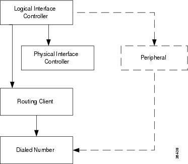
Interface Controllers
Each routing client must be associated with an interface controller. An interface controller operates on two levels: physical and logical. A physical device is a single instance of a device. A logical device is either a single physical device or more than one physical device running duplexed.
A physical interface controller can be a:
-
Network Interface Controller (NIC). An NIC communicates directly with the IXC's signaling network, reading call routing requests from the network and transferring them to the Central Controller. This chapter describes how to set up a NIC.
-
Peripheral Gateway (PG). A PG communicates with the ACD, PBX, or VRU at a contact center, monitoring status information from the peripheral and sending it to the Central Controller. The PG can also act as a routing client, sending routing requests to Unified ICM software.
Routing Client Subsystems Examples
You can associate more than one routing client with a single logical interface controller. For example, if a Unified ICM NIC is serving two AT&T Intelligent Call Processing (ICP) subsystems, as shown in the following figure, you can define each as a separate routing client through the single logical interface controller.
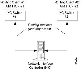
On the other hand, if you have two ACDs performing private network routing through two different peripheral gateways (PG), as shown in the following figure, you must define each as a routing client because each Peripheral Gateway is a separate logical interface controller.


 Feedback