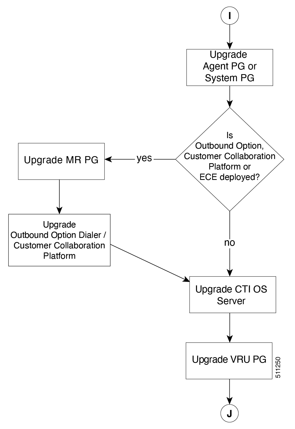
Upgrade Overview

Upgrade Overview

Unified CCE Redundant Central Controller Upgrade Flow

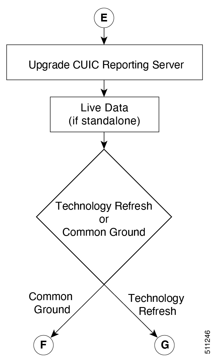
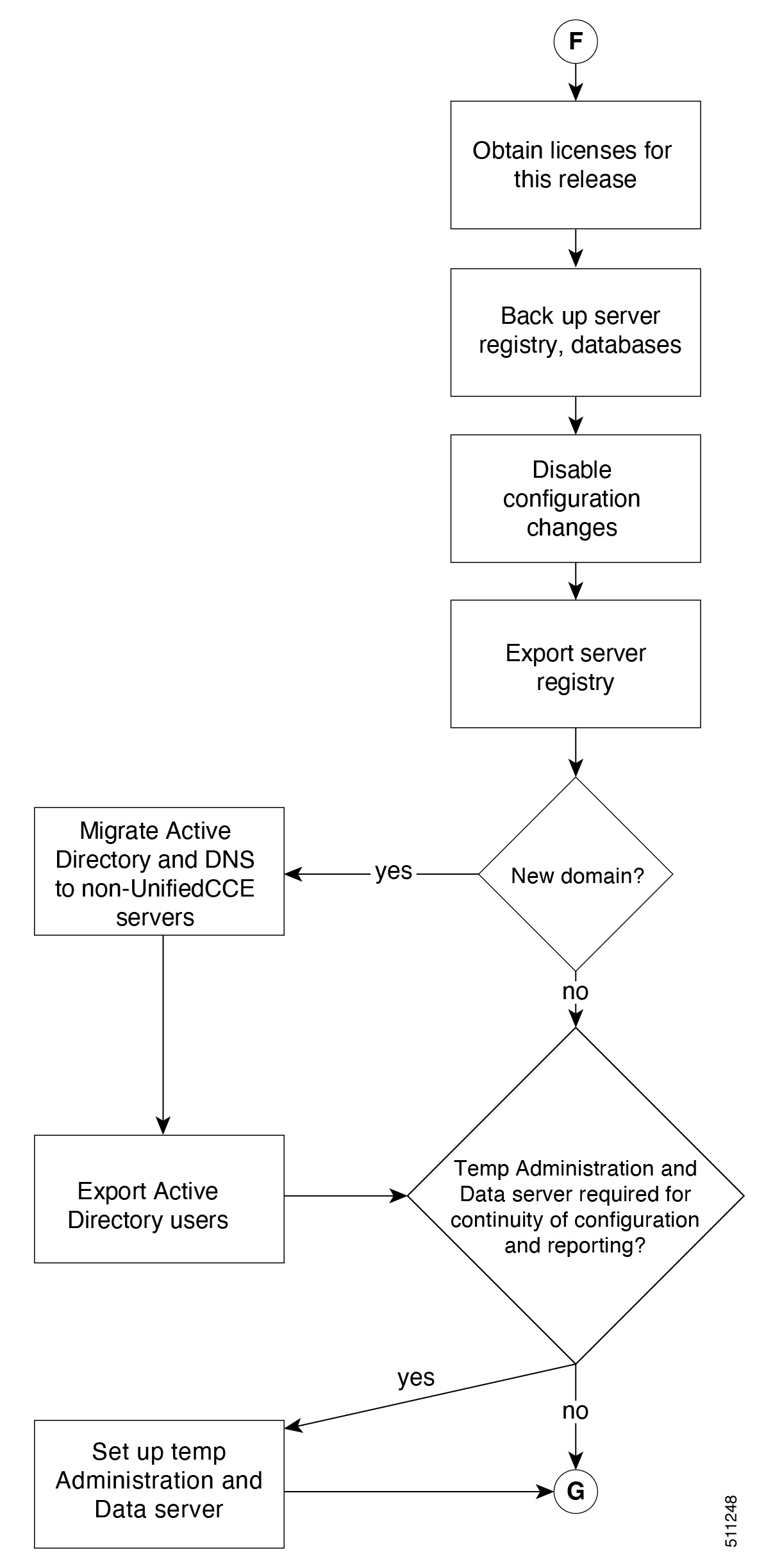
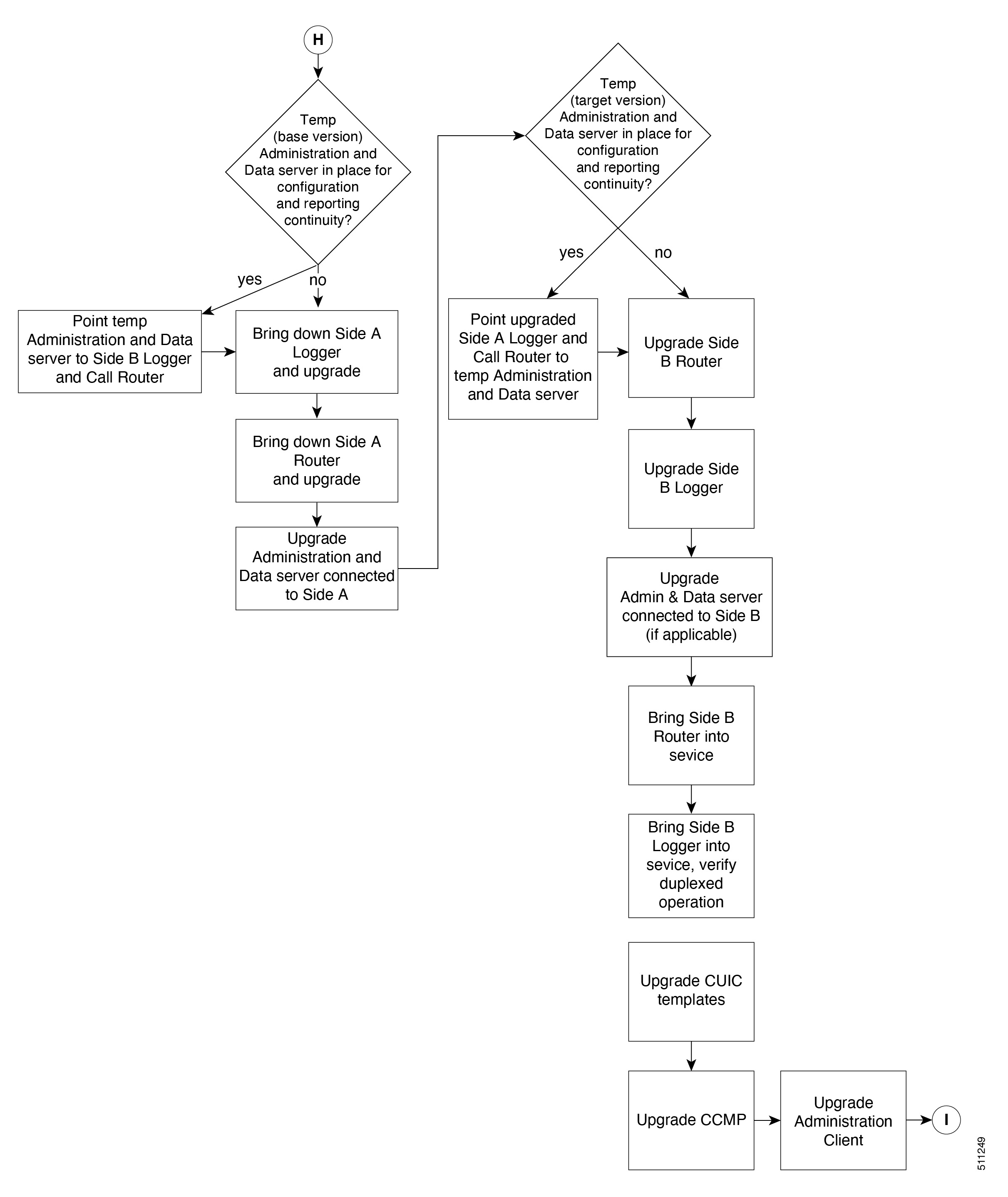
The Unified CCE central controller consists of the Logger, Router, and Administration & Data Server. When upgrading the Unified CCE portion of your contact center, the central controller is upgraded before the other Unified CCE components. While one side (Side A or B) of the redundant system is being upgraded, the other side (Side A or B) operates in stand-alone mode.

For redundant systems, the general flow for upgrading the Unified CCE central controller is as follows:

  1. Upgrade the Side A Logger and Router along with the Administration & Data Server identified to be upgraded first to verify operations on the upgraded Side A Logger and Router.

  2. Bring Side A into service and verify the operation. Side B is brought down as Side A is coming into service along with other non-upgraded Administration & Data Server(s).

  3. Upgrade the Side B Logger and Router along with remaining Administration & Data Server(s).

  4. Bring Side B into service and verify that duplexed operation begins.

Update VM Properties

Rather than re-create the VMs from the new version of the OVA, you can manually update the VM properties to match the new OVA. After you upgrade the vSphere ESXi and before you upgrade the Unified CCE components, update the properties of each VM to match the appropriate OVA, as follows:

  1. Stop the VM.

  2. Update the properties of each VM to match the properties of the appropriate OVA. Check the Virtualization for Unified Contact Center Enterprise at https://www.cisco.com/c/dam/en/us/td/docs/voice_ip_comm/uc_system/virtualization/virtualization-unified-contact-center-enterprise.html for descriptions of each OVA. Save your changes.

    See https://www.cisco.com/c/dam/en/us/td/docs/voice_ip_comm/uc_system/virtualization/virtualization-cisco-cloud-connect.html for details on Cloud Connect.

  3. Restart the VM.


Caution

Be careful when you upgrade the virtual machine network adapters. Done incorrectly, this upgrade can compromise the fault tolerance of your contact center.


SQL Security Hardening

You can optionally apply SQL security hardening when running the installer. If your company employs custom security policies, bypass this option. Most other deployments benefit from SQL security hardening.

For more information about SQL security hardening, see the Security Guide for Cisco Unified ICM/Contact Center Enterprise at http://www.cisco.com/c/en/us/support/customer-collaboration/unified-contact-center-enterprise/products-installation-and-configuration-guides-list.html.

Self-signed Certificate for CCE Web Application


Note

As part of the upgrade of CCE servers, self-signed certificates employed by CCE web applications like CCE web administration tool and Websetup, may get regenerated. You must add the new certificates to the trust list on the appropriate end devices.


Upgrade Tools

During the upgrade process, use the following tools as required:

  • ICM-CCE-Installer—The main Unified CCE Installer. It copies all files into relevant folders, creates the base registries, and installs needed third-party software such as JRE, Apache Tomcat, and Microsoft .NET Framework.


    Note

    Optionally, you can update the JRE installed by the Unified CCE Installer with a later version of the JRE. See Java Upgrades.

    If the ICM-CCE installer installs JRE on the Windows platform, the system retains only the Cisco approved CA certificates in the java certificate store, and removes all the unapproved certificates.


    Optionally, update the Apache Tomcat software. See Install Tomcat.

    You cannot run the installer remotely. Mount the installer ISO file only to a local machine.

    • Cisco Unified Intelligent Contact Management Database Administration (ICMDBA) Tool—Used to create new databases, modify or delete existing databases, and perform limited SQL Server configuration tasks.

    • Domain Manager—Used to provision Active Directory.

    • Web Setup—Used to set up the Call Routers, Loggers, and Administration & Data Servers.

    • Peripheral Gateway Setup—Used to set up PGs, the CTI server, and the Outbound Option dialer.

  • AdminClientInstaller—Installs the Administration Client on a system that is not running other Unified CCE components.

    The AdminClientInstaller is delivered on the installation media with the installer.

  • Administration Client Setup—Used to add, edit, or remove Administration Clients and Administration Client Instances.

    The Administration Client Setup is delivered on the installation media with the installer.

  • Enhanced Database Migration Tool (EDMT)—A wizard application that is used for all upgrades to migrate the HDS, Logger, and BA databases during the upgrade process.

    You can download the EDMT from Cisco.com by clicking Cisco Enhanced Data Migration Tool Software Releases.

    The prerequisites for running EDMT are:

    • EDMT requires Microsoft® ODBC Driver 17 for SQL Server® and Visual C++ Redistributable for Visual Studio 2015 (or higher). The latest version of these packages can be downloaded from the Microsoft website. However, a copy of the same is also available in the Prerequisites folder of EDMT.

    The EDMT displays status messages during the migration process, including warnings and errors. Warnings are displayed for informational purposes only and do not stop the migration. On the other hand, errors stop the migration process and leave the database in a corrupt state. If an error occurs, restore the database from your backup, fix the error, and run the tool again.


    Note

    • You can select either SQL Server Authentication or Windows Authentication during database migration. In certain scenarios, for example, where the source and destination machines are in different domains, SQL Server Authentication can be used.

    • If you are configuring SQL services to run as Virtual account (NT SERVICE) or Network Service account (NT AUTHORITY\NETWORK SERVICE), you must run EDMT as an administrator.

    • The installer, not the EDMT, upgrades the AW database for the Administration & Data Server.


  • User Migration Tool—A standalone Windows command-line application that is used for all upgrades that involve a change of domain. The tool imports the previously exported user accounts into the target domain during the upgrade.

    You can download the User Migration Tool from Cisco.com by clicking ICM User Migration Tool Software.


    Note

    User Migration Tool cannot be used for migrating users that are SSO enabled.


  • Regutil Tool—Used in Technology Refresh upgrades, exports the Cisco Systems, Inc. registry from the source machine during the preupgrade process. The output of the tool is required on the destination machine when running the Unified CCE Installer during the upgrade process.

    You can download the Regutil Tool from Cisco.com by clicking Contact Center Enterprise Tools.

Multistage Upgrade Workflow for 2000 Agents Deployment


Note

The multistage upgrade workflow is applicable for solution deployments with both main site and remote site (if available).

A CCE solution upgrade likely involves a multistage process; components are grouped in several stages for upgrading. At each stage in the upgrade, the upgraded components must interoperate with components that have not yet been upgraded to ensure the overall operation of the contact center. Therefore, it is important to verify this interoperability during the planning stages of the upgrade.

Before upgrading a production system, perform the upgrade on a lab system that mirrors your productionsystem to identify potential problems safely.


The following table details the required sequence for upgrading Unified CCE 2000 Agent Deployments components, and the minimum component groupings that must occur together within each stage. Follow each stage to completion within each maintenance window. Each maintenance window must accommodate any testing required to ensure system integrity and contact center operation.

You can combine more than one complete stage into a single maintenance window, but you cannot break any one stage into multiple maintenance windows.

Upgrade the CCE components as follows:


Note

  • Upgrade Agent Desktop, CUIC, Live Data, and IdS server along with the CCE Central Controller upgrade.

  • After upgrading Finesse, IdS, and CUIC, import the IdS certificates to the Finesse and CUIC servers.

  • Run Stage 3 and Stage 4 upgrades in the same maintenance window.


Stage

Component Group

Components

Notes

1

Cloud Connect

Platform Orchestration, Hybrid Features

Upgrade both the publisher and the subscriber. If you do not have Cloud Connect in your environment, Fresh Install the Cloud Connect. Refer Update VM Properties section in Upgrade Overview for Cloud connect upgrade prerequisite to increase the hard disk.

2

Queuing and self-service

Cisco Unified Customer Voice Portal (CVP) (Reporting Server, Call Server/VXMLServer, Unified Call Studio)

You must upgrade all sites before proceeding to the next stage.

For more information, see Installation and Upgrade Guide for Cisco Unified Customer Voice Portal at https://www.cisco.com/c/en/us/support/customer-collaboration/unified-customer-voice-portal/products-installation-guides-list.html.

3

Gateways
  • IOS Gateways (If used for ingress access only. If used for Outbound Option Dialer, see Stage 6.)

  • IOS VXML Gateways

  • Cisco Virtualized Voice Browser

4

Agent/Supervisor Desktop, Central Controller, and Reporting
  • ECE

  • Cisco Finesse

  • Unified CCE Rogger

  • Admin & Data server (AW/HDS/DDS)

  • CUIC-LD-IDS

  • CUIC Reporting Templates

5

Peripherals
  • Agent (Unified Communications Manager) PG

  • CTI Server

  • Outbound Option Dialer and SIP IOS Gateway

You can have many PGs located on different virtual machines. You can upgrade each PG virtual machine in its own maintenance window.

6

Peripherals
  • MR PG, VRU PG

  • CRM connector

You can have many PGs located on different virtual machines. You can upgrade each PG virtual machine in its own maintenance window.

7

Call Processing
  • Cisco Unified Communications Manager (Unified Communications Manager)

  • JTAPI on Agent (Unified Communications Manager) PG

You must install JTAPI client only when you upgrade to UCM 12.5.

If you upgrade to CUCM 12.5 on the M4 servers, ensure that you deploy CUCM off-box. CUCM 12.5 on-box deployment are only supported for M5 and HX M5 servers.

For more information, refer to Virtualization for Unified Contact Center Enterprise at https://www.cisco.com/c/dam/en/us/td/docs/voice_ip_comm/uc_system/virtualization/virtualization-unified-contact-center-enterprise.html.

Upgrade Flowcharts

The following diagram illustrates the solution-level upgrade flow for the Unified CCE 2000 Agent Deployment solution upgrade.

The following diagrams illustrate the stages of the component-level upgrade flows for the Unified CCE 2000 Agent Deployment solution upgrade. Each diagram covers one of the stages. The letter at the end of each flow indicates the start of the next flow that you are required to perform.

Multistage Upgrade Workflow for 4000 Agents and above Deployments

A Unified CCE solution upgrade likely involves a multistage process; components are grouped in several stages for upgrading. At each stage in the upgrade, the upgraded components must interoperate with components that have not yet been upgraded to ensure the overall operation of the contact center. Therefore, it is important to verify this interoperability during the planning stages of the upgrade.

Before upgrading a production system, perform the upgrade on a lab system that mirrors your production system to identify potential problems safely.

The following table details the required sequence for upgrading Unified CCE solution components, and the minimum component groupings that must occur together within each stage. Follow each stage to completion within each maintenance window. Each maintenance window must accommodate any testing required to ensure system integrity and contact center operation.

You can combine more than one complete stage into a single maintenance window, but you cannot break any one stage into multiple maintenance windows.


Note

  • For co-resident configurations, upgrade CUIC/LiveData/IdS server along with the UCCE Central Controller upgrade.

  • After you upgrade the Standalone Live Data server, upgrade the VMware Tools manually. After upgrading the VMware Tools, check the Check and upgrade VMware Tools before each power on box in VM Options > VM Edit Settings.


Upgrade the components that apply to your Unified CCE contact center as follows:

Stage

Component Group

Components

Notes

1

Cloud Connect

Platform Orchestration, Hybrid Features

Upgrade both the publisher and the subscriber. If you do not have Cloud Connect in your environment, Fresh Install the Cloud Connect. Refer Update VM Properties section for Cloud connect upgrade prerequisite to increase the hard disk.

2

Identity Service (IdS)/Single Sign-On(SSO)

IdS Server

3

Agent and supervisor desktops

Cisco Finesse

ECE

4 Queuing and self-service1

Cisco Unified Customer Voice Portal (CVP) (Operations Console, Reporting Server, Call Server/VXMLServer, Unified Call Studio)

5 Gateways
  • IOS Gateways (If used for ingress access only. If used for Outbound Option Dialer, see Stage 6.)

  • IOS VXML Gateways

  • Cisco Virtualized Voice Browser

6 Reporting server

CUIC server

7 Central Controller
  • Unified CCE Router

  • Unified CCE Logger

  • Admin & Data server (AW/HDS/DDS)

  • Standalone Live Data (if Deployed)

  • CUIC Reporting Templates

  • CCMP

  • Administration Client

Note 

For Live Data VM, you have to increase the RAM before upgrading. See https://www.cisco.com/c/dam/en/us/td/docs/voice_ip_comm/uc_system/virtualization/cisco-collaboration-virtualization.html

8 Peripherals
  • Agent (Unified Communications Manager) PG or System PG, plus

  • CTI Server

  • CTI OS Server

  • Outbound Option Dialer and SIP IOS Gateway

You can have many PGs located on different virtual machines. You can upgrade each PG virtual machine in its own maintenance window.

9 Peripherals
  • MR PG (if not collocated with Agent PG on VM), plus VRU PG (if not collocated with Agent PG on VM)

  • Unified CCE Gateway PG (if not collocated with Agent PG on VM)

  • CRM connector

You can have many PGs located on different virtual machines. You can upgrade each PG virtual machine in its own maintenance window.

10 Agent desktop client software

CTI OS (Agent/Supervisor Desktops)

You can have many desktops located in many different sites. You can upgrade CTI OS desktops in multiple maintenance windows; the later upgrade stages are not dependent on the completion of this stage.

11 Call Processing
  • Cisco Unified Communications Manager (Unified Communications Manager)

  • JTAPI on Agent (Unified Communications Manager) PG

If you upgrade to CUCM 12.5 on the M4 servers, ensure that you deploy CUCM off-box. CUCM 12.5 on-box deployment are only supported for M5 and HX M5 servers.

For more information, refer to Virtualization for Unified Contact Center Enterprise at http://www.cisco.com/c/dam/en/us/td/docs/voice_ip_comm/uc_system/virtualization/virtualization-unified-contact-center-enterprise.html.

1 If you are using Unified IP IVR for self-service and queueing, see Getting Started with Cisco Unified IP IVR.

Upgrade Flowcharts


Note

The multi-stage upgrade flowchart is not applicable for Centralized UCCE 2K deployments that essentially employ a co-resident CUIC/LiveData/IdS server, and have a single Agent PG VM pair.

Note

After upgrading Finesse, IdS, and CUIC, import IdS certificates on Finesse and CUIC servers.


The following diagram illustrates the solution-level upgrade flow for Cisco Contact Center Enterprise solution upgrade.

The following diagrams illustrate the stages of the component-level upgrade flows for a Cisco Unified Contact Center Enterprise solution upgrade. Each diagram covers one of the stages. The letter at the end of each flow indicates the start of the next flow that you are required to perform.

Figure 1.


Data Migration Considerations


Note

The EDMT may take a long time to migrate, backup, or restore the data, as the file sizes can be several gigabytes (GB). If the EDMT tool is not responding during data migration or the data migration takes a long time, check the Event logs in the Microsoft Windows Event Viewer tool. The logs may show SQL or BACKUP failure events. These events may occur because of file system errors or hardware errors and failures. Analyze and fix these errors before re-running the EDMT tool.


To reduce data migration time, consider reducing the database size by:

  • Removing redundant records, especially call detail records (RCD, RCV, TCD, and TCV tables). However, removing records affects the availability of historical reports; knowledge of the HDS schema is required.

  • Purging the Logger database of all data that was already replicated to the HDS (25 GB or less).

  • Using more efficient hardware, especially on I/O subsystems:

    • RAID 1 + 0

    • I/O Cache – more is better

Enable the Tempdb log to expand up to 3 GB.


Note

When you upgrade to Cisco Unified Contact Center Enterprise, Release , the Do Not Call table that existed before the upgrade is not available. Therefore, you must import the Do Not Call table.


Required Disk Space for Migration

  1. Run EXEC sp_spaceused command in the SQL Server.

  2. Determine the following:

    • DUS (Database Used Size).

      Calculated as:

      Database Used Size (DUS) = (database_size – unallocated space)

    • Required disk space by EDMT for backup of database

      Calculated as:

      Space that is used for backup = 1.2 times of DUS.


    Note

    Note: When the backup and restore drive are same, then required disk space by EDMT is equal to restore database size plus space used for backup.

    Note

    When the backup and restore has to be done through EDMT, and since the database backup contains encrypted data, this process cannot be performed unless the source certificate that encrypted the database is copied to the destination server.

    Follow the procedures outlined in the below Microsoft documentation to restore the certificate on destination server.

    If you do not want to move the encrypted backup, then disable TDE on the source database, perform the backup and restore through EDMT, and enable TDE on destination database. To enable and disable TDE on the database, see Enable and Disable TDE on a Database.


Time Guidelines and Migration Performance Values

For a close estimate of time and space requirements, run EDMT against a copy of your production database on hardware that is similar to your production environment, in a lab environment. For customers who do not have the facility, the following sections provide information that is gathered while performance testing in the labs at Cisco Systems, Inc.

  • Typical database migration performance values: The following table provides high-level guidelines for the time that is taken to upgrade the Loggers and HDSs based on internal upgrade testing with hardware C240 M4. Actual times may vary based on the parameters previously mentioned.

  • Backup and Restore - Technology Refresh only: The backup speed depends on the speed of the network, and the speed of the disk sub-system. The faster the network, the sooner the network copy.

Database Used Size (GB)

Backup/Restore Time (hours)

Data Migration Time (minutes)

Total Time (hours)

500 GB

1.5-2 hrs

< 2 mins

2 - 2.5 hrs


Note

  • The values in the Database Used Size column are based on the amount of disk space that is used by the source database, and not the size of the disk it resides on.

  • The values in the Backup Time and Restore Time columns assumes that the network meets the minimum requirements.

    For more information about the minimum requirements, refer to the Virtualization for Unified Contact Center Enterprise at http://www.cisco.com/c/dam/en/us/td/docs/voice_ip_comm/uc_system/virtualization/virtualization-unified-contact-center-enterprise.html .

  • For Technology Refresh upgrades, have the fastest network possible (gigabit through one network switch) between the source and the destination machines. Use of a crossover cable is not supported because it lacks buffer memory and can cause data loss.


Enable and Disable TDE on a Database

To enable Transparent Data Encryption (TDE) on a database, perform the following:


Note

These steps are to be performed with sysadmin user permission.


  1. Create a server certificate data encryption key.

    USE master
    GO
    CREATE CERTIFICATE DEKCert WITH SUBJECT = 'DEK Certificate'
    GO
  2. Create a backup of the server certificate data encryption key.

    BACKUP CERTIFICATE DEKCert TO FILE = 'c:\DEKCert'
    WITH PRIVATE KEY ( FILE = 'c:\temp\DEKCertPrivKey' ,
    ENCRYPTION BY PASSWORD = 'C1sco123=' )
    GO
    
  3. Create database encryption key for the database to configure transparent data encryption. In the following query, ucce_sideA is the name of the active database.

    USE ucce_sideA
    GO
    CREATE DATABASE ENCRYPTION KEY
    WITH ALGORITHM = AES_256
    ENCRYPTION BY SERVER CERTIFICATE DEKCert
    GO
  4. Enable database encryption. Run the following query where ucce_sideA is the name of the active database.

    ALTER DATABASE ucce_sideA SET ENCRYPTION ON

    Note

    By setting encryption on, a background task starts encrypting all the data pages and the log file. This can take a considerable amount of time, depending on the size of the database. Database maintenance operations should not be performed when this encryption scan is running.


  5. To query the status of the database encryption and its percentage completion, query the new sys.dm_database_encryption_keys.

    SELECT DB_NAME(e.database_id) AS DatabaseName,
    e.database_id,
    e.encryption_state,
    CASE e.encryption_state
    WHEN 0 THEN 'No database encryption key present, no encryption'
    WHEN 1 THEN 'Unencrypted'
    WHEN 2 THEN 'Encryption in progress'
    WHEN 3 THEN 'Encrypted'
    WHEN 4 THEN 'Key change in progress'
    WHEN 5 THEN 'Decryption in progress'
    END AS encryption_state_desc,
    c.name,
    e.percent_complete
    FROM sys.dm_database_encryption_keys AS e
    LEFT JOIN master.sys.certificates AS c
    ON e.encryptor_thumbprint = c.thumbprint
To disable TDE on a database, perform the following:
USE master;
GO
ALTER DATABASE ucce_sideA SET ENCRYPTION OFF;
GO
-- Remove Encryption Key from Database
USE ucce_sideA;
GO
DROP DATABASE ENCRYPTION KEY;
GO

Silent Upgrade

There are situations where a silent upgrade can be used in running an installation wizard. You can run a silent installation when performing a fresh install or an upgrade.

For more information, see Silent Installation.

Unified CCE Upgrade Overview

The supported upgrade paths to 12.6(1) are as follows:

  • Release 12.0(1) to 12.5(1) followed by 12.6(1)

  • Release 12.5(1) to 12.6(1)

Upgrade Prerequisites

Before you begin

  • Make sure that Windows Update is not running in parallel when you begin installation.

  • Before you upgrade the Cisco VOS based servers such as the Live Data server, check the Check and upgrade VMware Tools before each power on box in the VM's Options > Edit Settings.

    For more information on VMware Tools upgrade, see the VMware documentation.

  • The minimum disk space required to perform the upgrade is 2175 MB.

Custom Truststore to Store Component Certificates

Starting CCE 12.6(1), a new custom truststore is created under the ICM Installation directory <ICM install directory>\ssl\cacerts to store all the component certificates. With this new custom truststore, you don't need to export and import the certificates each time Java is updated in the system.

Post the upgrade to 12.6(1), you should export the certificates from the Java truststore to the custom truststore under the ICM Installation directory <ICM install directory>\ssl\cacerts.

Export the certificate from the Java truststore:

  • Execute the command at the command prompt: cd %JAVA_HOME%\bin.


    Important

    Use CCE_JAVA_HOME if upgrading from 12.5(1a) or 12.5(1) with ES55 (mandatory OpenJDK ES).
  • Export the certificates of all the components imported into the truststore.

    The command to export the certificates is keytool -export -keystore <JRE path>\lib\security\cacerts -alias <alias of the component> -file <filepath>.cer
  • Enter the truststore password when prompted.

Import the certificate to the custom truststore:

  • Execute the command at the command prompt: cd %CCE_JAVA_HOME%\bin.

  • Import the certificates for all the components that you exported from the Java truststore.

    The command to import certificates is keytool -import -keystore <ICM install directory>\ssl\cacerts -file <filepath>.cer -alias <alias>.
  • Enter the truststore password when prompted.

  • Enter 'yes' when prompted to trust the certificate.

Upgrade Cloud Connect

Follow the steps to install the ISO file using the Cloud Connect Command line interface (CLI).

You can also install the ISO using the upgrade procedure in the Cisco Unified Operating System Administration web interface. For more information, see Access Unified OS Administration.

Before you begin:

Before you begin the upgrade from 12.5(1) to 12.6(1), check if the cop ucos.keymanagement.cop.sgn is applied on the base version. The upgrade fails if you do not install the cop ucos.keymanagement.cop.sgn.

Download the ISO file from the download software page for Cloud Connect https://software.cisco.com/download/home/268439622/type/283914286/release/12.6(1) to the SFTP server that can be accessed from the Cloud Connect system.

  1. Log in to Cloud Connect CLI and specify the System Administration username and password.

  2. Enter the command utils system upgrade initiate to initiate the ISO installation.

  3. Select Remote File System from source list page.

  4. Enter the remote path to the directory on the SFTP server where you have downloaded the ISO file.


    Note

    If the ISO file is located on a Linux or UNIX server, you must enter a forward slash (/) at the beginning of the directory path. For example, if the COP file is in the patches directory, enter /patches. If the ISO file is located on a Windows server, check with your system administrator for the correct directory path.


  5. Enter the SFTP server name or IP address and then enter the credentials.

    It is optional for you to enter the SMTP Host Server name.

  6. Select the transfer protocol as SFTP. The system displays the list of ISO files available in the SFTP location.

  7. Select the number corresponding to the ISO file that you want to install and press Enter.

  8. Enter the following options when you are prompted Switch to new version if the upgrade is successful (yes/no).

    • Enter yes to automatically switch the version.

    • Enter no if you need to manually switch the version after all the nodes are upgraded (refer step 10 for more details).


    Note

    Verify if the node is upgraded to 12.6, after successful switch version (where active version is 12.6 and inactive version is 12.5).


  9. In cluster setup, first complete the upgrade on the publisher node and perform the upgrade on the subscriber node. After successful upgrades, perform switch version using the command utils system switch-version first on the publisher node and later on the subscriber nodes.


    Note

    Verify if the nodes are upgraded to 12.6, after successful switch version of the publisher node and subscriber nodes (where active version is 12.6 and inactive version is 12.5).