Configure Courtesy Callback
The following diagram shows the components that you must configure for Courtesy Callback.
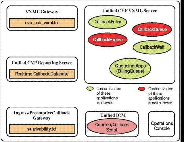
Complete the following procedures for Courtesy Callback configurations:
Configure Gateway
Configure the VXML Gateway for Courtesy Callback
Complete the following procedure to configure the VXML gateway for Courtesy Callback:
Procedure
|
Step 1 |
Copy cvp_ccb_vxml.tcl from the CVP Operations Console to the flash memory of the gateway, as follows:
|
||
|
Step 2 |
Log on to VXML gateway. |
||
|
Step 3 |
Add the cvp_cc service to the configuration service cvp_cc flash:cvp_ccb_vxml.tcl. This service does not require any parameters. |
||
|
Step 4 |
Enter the following command to load the application: call application voice load cvp_cc |
||
|
Step 5 |
On the VoIP dial-peer that defines the VRU from Unified CCE, verify that the codec can be used for recording. Example:The following example verifies that g711ulaw can be used for recording in Courtesy Callback: |
||
|
Step 6 |
Configure the following to ensure that SIP is setup to forward SIP INFO messaging: |
||
|
Step 7 |
To play the beep to prompt the caller to record their name in the BillingQueue example script add the following text to the configuration: vxml version 2.0
Example: |
Configure the Ingress Gateway for Courtesy Callback
Complete the following procedure to configure the ingress gateway for courtesy callback:
Procedure
|
Step 1 |
Copy surviability.tcl from the Operations Console to the flash memory of the gateway, as follows:
|
|
Step 2 |
Log onto the ingress gateway. |
|
Step 3 |
Add the following to the survivability service: param ccb id:<host name or ip of this
gateway>;loc:<location name>;trunks:<number of callback
trunks>
Example: |
|
Step 4 |
Create the incoming POTS dial peer, or verify that the survivability service is being used on your incoming POTS dial peer. Example: |
|
Step 5 |
Create outgoing POTS dial peers for the callbacks. These are the dial peers that place the actual call back out to the PSTN. Example: |
|
Step 6 |
Use the following configuration to ensure that SIP is set up to forward SIP INFO messaging: voice service voip signaling forward unconditional |
Configure CUBE-E for Courtesy Callback
 Note |
If you are using CUBE-E then you need sip profile configuration and apply it on outgoing dial-peer through cvp. See the below the example: |
A "sip-profile¨ configuration is needed on ISR CUBE E for the courtesy callback feature. To configure the "sip-profile", the following must be added
voice class sip-profiles
                                       			 103
request INVITE sip-header
                                       			 Call-Info add "X-Cisco-CCBProbe: <ccb param>"
where "<ccb param>" is the "ccb" parameter defined in the survivability service. Add this "sip-profile" to the outgoing dial-peer to the CVP.
The following is a configuration example
 voice class sip-profiles
                                       			 103
 request INVITE sip-header
                                       			 Call-Info add "X-Cisco-CCBProbe: id:10.10.10.180;sydlab;trunks:4"
dial-peer voice 5001
                                       			 voip
description Comprehensive
                                       			 outbound route to CVP
destination-pattern
                                       			 5001
session protocol
                                       			 sipv2
session target
                                       			 ipv4:10.10.10.10
dtmf-relay rtp-nte
voice-class sip profiles
                                       			 103
codec g711ulaw
no vad
In the above example, 10.10.10.180 is the CUBE IP and 10.10.10.10 is the CVP Call Server IP.
Note |
If CUBE E is used for Courtesy Call Back then under voice service voip class in CUBE E must have media flow-through for Courtesy Call Back to work. |
Configure Unified CVP
Configure the Reporting Server for Courtesy Callback
A reporting server is required for the Courtesy Callback feature. Complete the following procedure to configure a reporting server for Courtesy Callback:
Before you begin
Install and configure the Reporting Server.
Procedure
|
Step 1 |
In the Operations Console, select System > Courtesy Callback. The Courtesy Callback Configuration page displays. |
||
|
Step 2 |
Choose the General tab. |
||
|
Step 3 |
Click the Unified CVP Reporting Server drop-down, and select the Reporting Server to use for storing Courtesy Callback data. |
||
|
Step 4 |
If required, select Enable secure communication with the Courtesy Callback database. |
||
|
Step 5 |
Configure allowed and disabled dialed numbers. These are the numbers that the system should and should not call when it is making a Courtesy Callback to a caller.
|
||
|
Step 6 |
Adjust the Maximum Number of Calls per Calling Number to the desired number. By default, this is set to 0 and no limit is imposed. This setting allows you to limit the number of calls that are eligible to receive a callback from the same calling number. If this field is set to a positive number (X), then the Courtesy Callback Validate element only allows X callbacks per calling number to go through the preemptive exit state at any time. If there are already X callbacks offered for a calling number, new calls go through the none exit state of the Validate element. In addition, if no calling number is available for a call, the call always goes through the none exit state of the Validate element. |
||
|
Step 7 |
Choose the Call Server Deployment tab and move the Call Server you want to use for Courtesy Callbacks from the Available box to the Selected box. |
||
|
Step 8 |
Click Save. The configuration becomes active (is deployed) the next time the Reporting Server is restarted. |
||
|
Step 9 |
You can also deploy the new Reporting Server configuration immediately by clicking Save & Deploy.
|
Configure the Call Studio Scripts for Courtesy Callback
Procedure
|
Step 1 |
Access the .zip file from the CVP OAMP machine from the location C:\Cisco\CVP\OPSConsoleServer\StudioDownloads\CourtesyCallbackStudioScripts.zip. |
||
|
Step 2 |
Extract the example Call Studio Courtesy Callback scripts contained in CourtesyCallbackStudioScripts.zip to a folder of your choice on the computer running CallStudio. Each folder contains a Call Studio project having the same name as the folder. The five individual project comprise the Courtesy Callback feature.
|
||
|
Step 3 |
Modify the scripts BillingQueue, CallbackEntry, and CallbackWait to suit your business needs. |
||
|
Step 4 |
Start Call Studio by selecting Start > All Programs > Cisco > Cisco Unified Call Studio. |
||
|
Step 5 |
Select File > Import. The Import dialog box displays. |
||
|
Step 6 |
Expand the Call Studio folder and select Existing Call Studio Project Into Workspace. |
||
|
Step 7 |
Click Next . The Import Call Studio Project From File System displays. |
||
|
Step 8 |
Browse to the location where you extracted the call studio projects. For each of the folders that were unzipped, select the folder (for example BillingQueue) and select Finish. The project is imported into Call Studio. |
||
|
Step 9 |
Repeat the action in previous step for each of the five folders. The five projects display in the upper-left of the Navigator window. |
||
|
Step 10 |
Update the Default Audio Path URI field in Call Studio to contain the IP address and port value for your media server. |
||
|
Step 11 |
For each of the Call Studio projects previously unzipped, complete the following steps:
|
||
|
Step 12 |
Under BillingQueue Project, if required, change the music played to the caller while on hold.
|
||
|
Step 13 |
Under CallbackEntry Project, if required, modify the caller interaction settings in the SetQueueDefault_01 node.
|
||
|
Step 14 |
In the CallbackEntry project, on the Wants Callback page, configure the following: |
||
|
Step 15 |
Right-click each Courtesy Callback project in the Navigator window and select Validate. |
||
|
Step 16 |
Right-click on one of the project and click Deploy. |
||
|
Step 17 |
Check the check box against each project to select the required projects. |
||
|
Step 18 |
In the Deploy Destination area, select Archive File and click Browse. |
||
|
Step 19 |
Navigate to the archive folder that you have set up. Example: |
||
|
Step 20 |
Enter the name of the file. Example: |
||
|
Step 21 |
Click Save. |
||
|
Step 22 |
In the Deploy Destination area click Finish. |
||
|
Step 23 |
Log in to OAMP and choose Bulk Administration\File Transfer\VXMLApplications. |
||
|
Step 24 |
Select the VXML Server to which you want to deploy the applications. |
||
|
Step 25 |
Select the zip file that contains the applications. Example: |
||
|
Step 26 |
Click Transfer. |
||
|
Step 27 |
Right-click each of the projects and click Deploy, then click Finish. |
||
|
Step 28 |
Using windows explorer, navigate to %CVP_HOME%\VXMLServer\applications. |
||
|
Step 29 |
For each of the five Courtesy Callback applications, open the project's admin folder, in%CVP_Home%\VXMLServer\applications, and double-click deployApp.bat to deploy the application to the VXML Server. |
||
|
Step 30 |
Verify that all the applications are running by going into %CVP_HOME%\VXMLServer\admin and double-clicking status.bat. All five applications should display under Application Name and with the status Running. |
Configure the Media Server for Courtesy Callback
Several Courtesy Callback specific media files are included with the sample scripts for Courtesy Callback. Complete the procedure to configure the Media Server for Courtesy Callback:
Procedure
|
Step 1 |
During the Unified CVP installation, the media files are copied as: %CVP_HOME%\OPSConsoleServer\CCBDownloads\CCBAudioFiles.zip. |
|
Step 2 |
Unzip the special audio files and copy to your media server VXMLServer\Tomcat\webapps\CVP\audio. The sample scripts are set up to use the default location "\CVP\audio" for the audio files. |
|
Step 3 |
Change the default location of the audio files in the sample scripts to be your media server path. |
Configure Unified CCE
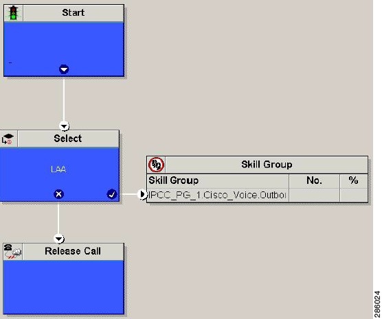
Configure the ICM Script for Courtesy Callback
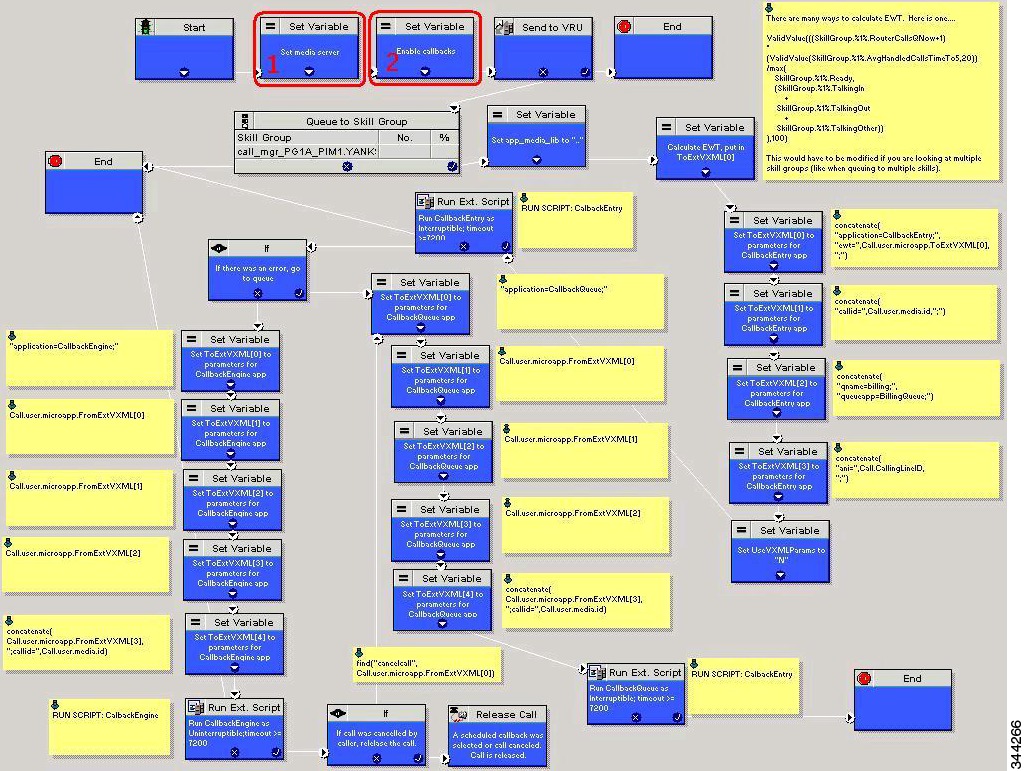
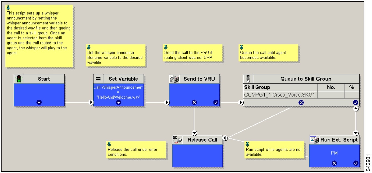
Following figure shows the sample Courtesy Callback ICM script.
Complete the following procedure to configure ICM to use the sample Courtesy Callback ICM script:
Procedure
|
Step 1 |
Copy the CCE example script, CourtesyCallback.ICMS to the CCE Admin Workstation.
|
||
|
Step 2 |
In Script Editor, select File > Import Script...
|
||
|
Step 3 |
In the script location dialog, select the CourtesyCallback.ICMS script and click Open. You can bypass the set variable "Set media server" Highlighted as number 1 node in the Sample Courtesy Callback ICM script, as VXML Server, Call Server, and Media Server are collocated. |
||
|
Step 4 |
Define a new ECC variable for courtesy callback. A new ECC variable is used to determine if a caller is in a queue and can be offered a callback. |
||
|
Step 5 |
Navigate to ICM Admin Workstation > ICM Configuration Manager > Expanded Call Variable List tool to create the ECC Variable user.CourtesyCallbackEnabled specific to Courtesy Callback. |
||
|
Step 6 |
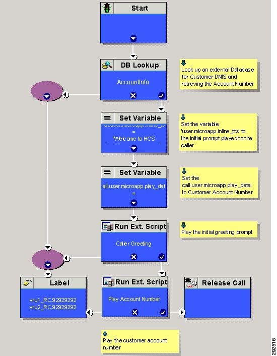
Set up the following parameters that are passed to CallbackEntry (VXML application): Example:
ewt is calculated in Block #2. qname is the name of the VXML Server queue into which the call will be placed. There must be a unique qname for each unique resource pool queue. queueapp is the name of the VXML Server queuing application that is run for this queue. ani is the caller's calling Line Identifier. |
||
|
Step 7 |
Create Network VRU Scripts. |
||
|
Step 8 |
Navigate to ICM Configuration Manager > Network VRU Script List tool, create the following Interruptible Script Network VRU Scripts. Name: VXML_Server_Interruptible Network VRU: Select your Type 10 CVP VRU VRU Script Name: GS,Server,V,interrupt Timeout: 9000 seconds Interruptible: Checked |
||
|
Step 9 |
Choose ICM Configuration Manager > Network VRU Script List tool to create the following Non-Interruptible Script Network VRU Scripts. Name - VXML_Server_NonInterruptible Network VRU - Select your Type 10 CVP VRU VRU Script Name - GS,Server,V, nointerrupt Timeout - 9000 seconds ( must be greater than the maximum possible call life in Unified CVP)Interruptible: Not Checked |
||
|
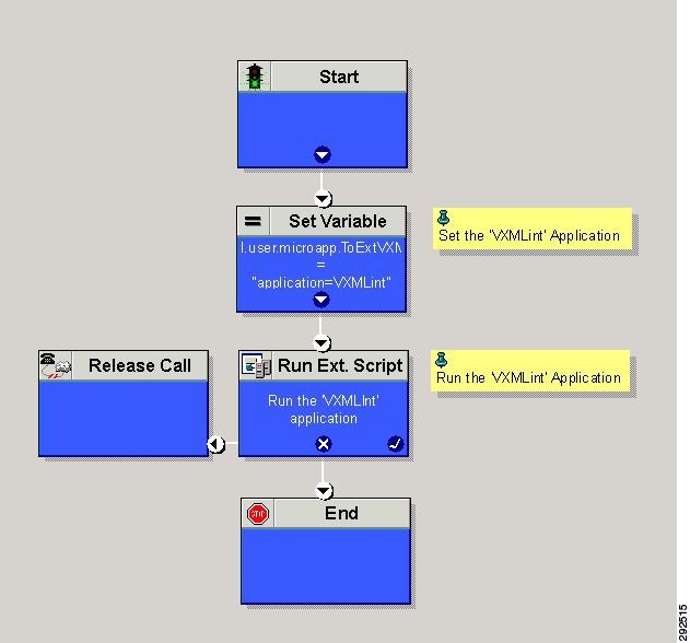
Step 10 |
Verify that the user.microapp.ToExtVXMLECC variable is set up for an array of five items with a minimum size of 60 characters and the user.microapp.FromExtVXML variable is set up for an array of four with a minimum size of 60 characters.
Verify that you have at least one available route and skill group to map to the route and skillgroup in the example script. |
||
|
Step 11 |
Save the script, then associate the call type and schedule the script.
|
 Feedback