Accessories Overview for Cisco IP Phone 8800 Series with Multiplatform Firmware
|
Accessory |
Type |
Cisco IP Phone |
||||
|---|---|---|---|---|---|---|
|
8811 and 8841 |
8845 |
8851 |
8861 |
8865 |
||
|
Cisco Accessory |
||||||
|
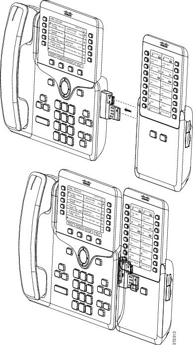
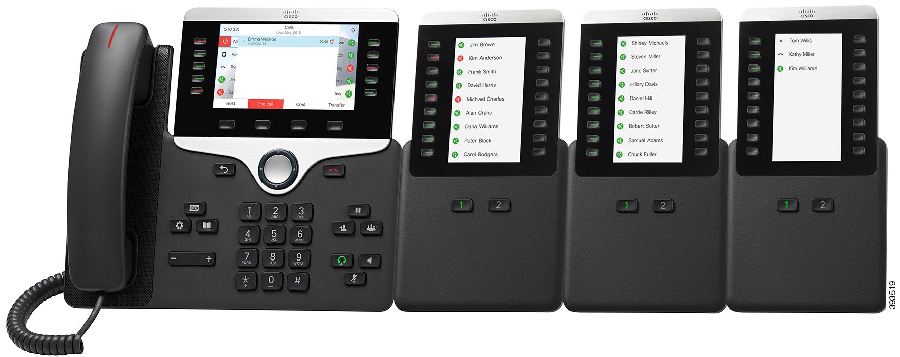
Cisco IP Phone 8800 Key Expansion Module |
Add-on module |
Not supported |
Not supported |
Supported |
Supported |
Supported |
|
Supports up to 2 expansion modules. |
Supports up to 3 expansion modules. |
|||||
|
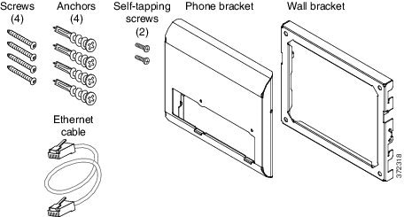
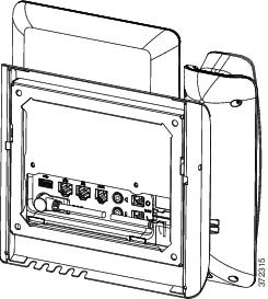
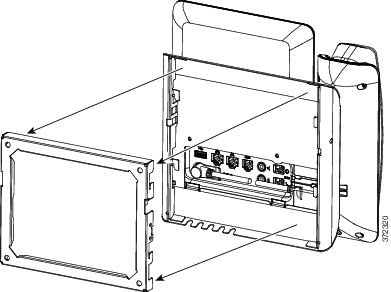
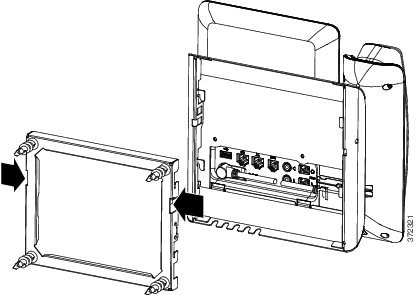
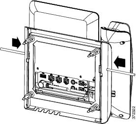
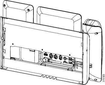
Wall Mount Kit |
Supported |
Supported |
Supported |
Supported |
Supported |
|
|
Footstand |
Supported |
Supported |
Supported |
Supported |
Supported |
|
|
Cable Lock |
Supported |
Supported |
Supported |
Supported |
Supported |
|
|
Cisco Headset 520 Series |
USB |
Not supported |
Not supported |
Supported |
Supported |
Supported |
|
Cisco Headset 530 Series |
Standard RJ9 |
Supported |
Supported |
Supported |
Supported |
Supported |
|
USB Adapter |
Not supported |
Not supported |
Supported |
Supported |
Supported |
|
|
Cisco Headset 560 Series with Standard Base Cisco Headset 560 Series with Multibase |
Standard RJ9 and AUX |
Supported |
Supported |
Supported |
Supported |
Supported |
|
USB |
Not supported |
Not supported |
Supported |
Supported |
Supported |
|
|
Cisco Headset 730 |
Bluetooth* |
Not supported |
Not supported |
Not supported |
Not supported |
Not supported |
|
USB Adapter |
Not supported |
Not supported |
Supported |
Supported |
Supported |
|
|
USB-C Cable |
Not supported |
Not supported |
Supported |
Supported |
Supported |
|
|
*—For the Bluetooth connection with Cisco IP Phone Multiplatform Phones, the limited call features (for example, answer or end a call) are available. The call features will be fully supported in a future release. Currently, we recommend that you use the Cisco Headset 730 by a USB adapter or a USB-C cable. |
||||||
|
Third-Party Accessories |
||||||
|
Headsets: See Third Party Headsets. This section includes information about each headset type. |
Analog |
Supported |
Supported |
Supported |
Supported |
Supported |
|
Analog Wideband |
Supported |
Supported |
Supported |
Supported |
Supported |
|
|
Bluetooth* |
Not supported |
Supported |
Supported |
Supported |
Supported |
|
|
USB |
Not supported |
Not supported |
Supported |
Supported |
Supported |
|
|
Electronic Hookswitch |
Supported |
Supported |
Supported |
Supported |
Supported |
|
|
See Note 1. |
See Note 2. |
|||||
|
Microphones: See External Speakers and Microphone. |
External PC |
Not supported |
Not supported |
Not supported |
Supported |
Supported |
|
Speakers: See External Speakers and Microphone. |
External PC |
Not supported |
Not supported |
Not supported |
Supported |
Supported |
 Note |
|


 Feedback