Key Expansion Modules

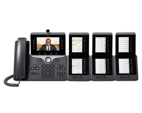
Cisco IP Phone Key Expansion Module Setup Overview

Key expansion modules add extra line appearances, speed dials, or programmable buttons to the phone. The programmable buttons can be set up as phone line buttons, speed-dial buttons, or phone feature buttons. But Simplified dialing is not supported on expansion modules.
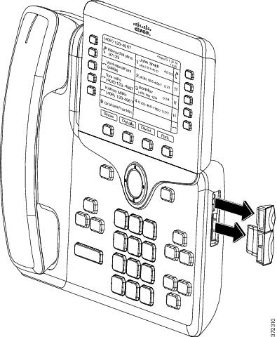
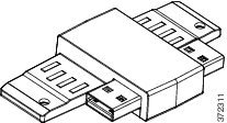
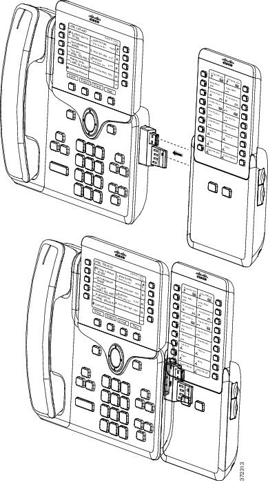
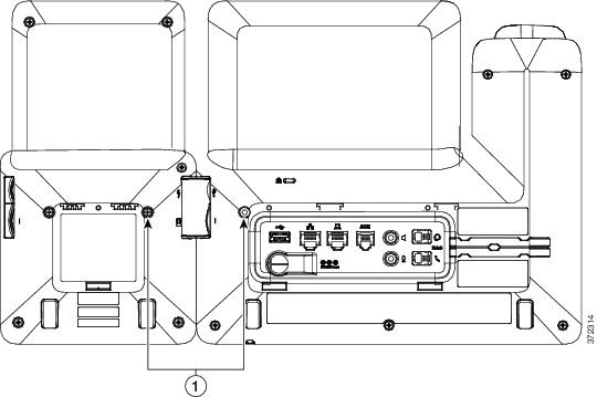

Caution

The slots in the side of the phone are designed only for use with the spine connectors on the key expansion module. Insertion of other objects permanently damages the phone.


There are 3 expansion modules available:
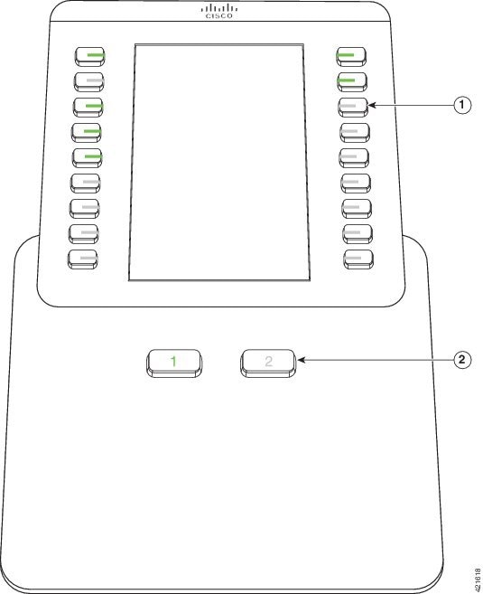
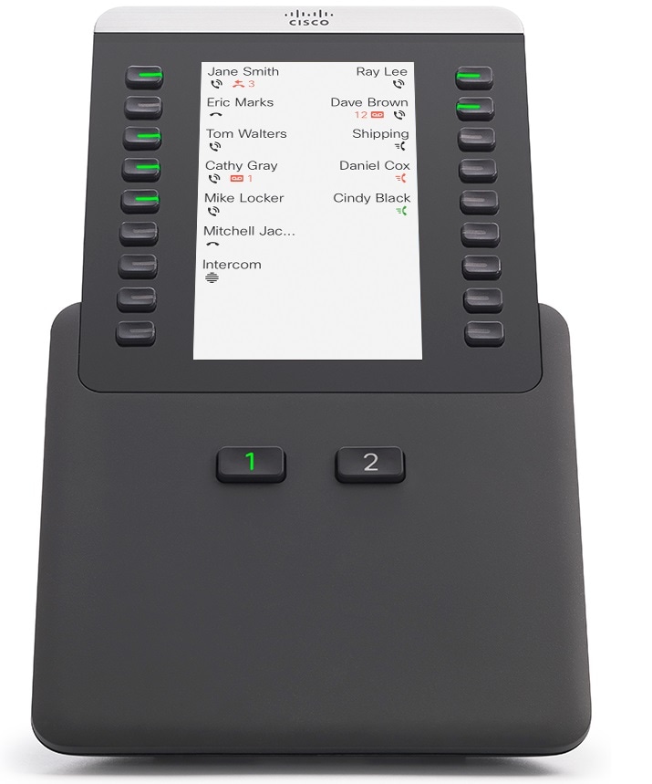
  • Cisco IP Phone 8800 Key Expansion Module—Single LCD screen module, 18 line keys, 2 pages, configure with one or two column displays.

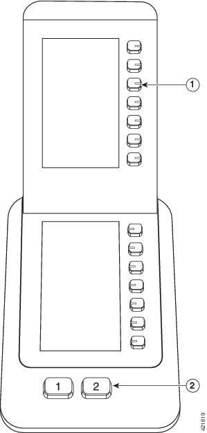
  • Cisco IP Phone 8851/8861 Key Expansion Module—Dual LCD screen module for audio phones, 14 line keys, 2 pages, configure with one-column display only. If you use Enhanced line mode, and you receive a call on a key expansion line, then a Call Alert displays on the phone, and the Caller ID displays on the expansion module line.

  • Cisco IP Phone 8865 Key Expansion Module—Dual LCD screen module for video phones, 14 line keys, 2 pages, configure with one-column display only. If you receive a call on a key expansion line, then a Call Alert displays on the phone, and the Caller ID displays on the expansion module line.

The Cisco IP Phone 8851/8861 Key Expansion Module and the Cisco IP Phone 8865 Key Expansion Module require firmware release 12.0(1) or later, and Cisco Unified Communications Manager 10.5(2) or later to function. Enhanced line mode (ELM) is supported only on the Cisco IP Phone 8851/8861 Key Expansion Module and the Cisco IP Phone 8865 Key Expansion Module. ELM is not supported on the single LCD expansion modules.

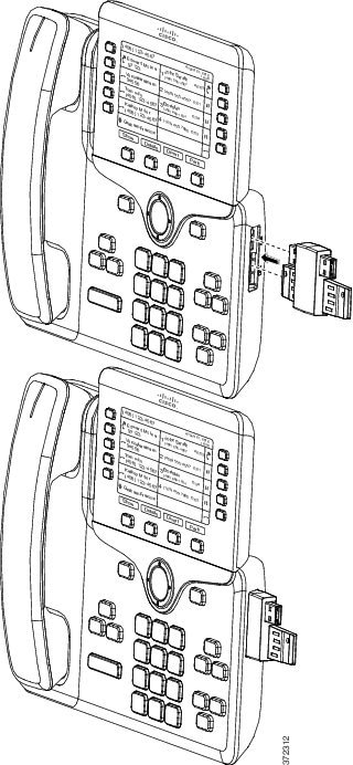
You can use more than one expansion module per phone. The Cisco IP Phone 8851 and 8851NR support up to 2 modules. The Cisco IP Phone 8861, 8865, and 8865NR support up to 3 modules. But each module must be the same type. This means that you cannot mix audio expansion modules with video expansion modules. You also cannot use a video expansion module on an audio phone or an audio expansion module on a video phone.

Most calling features are supported on your expansion module, and they are configured by your administrator from the Cisco Unified Communications Manager. If a feature is available on the Self Care Portal, then you can add the feature to your expansion module.

When adding features to your expansion module, remember that each line button supports only one feature. You cannot add more features than the number of programmable line keys on your expansion module.

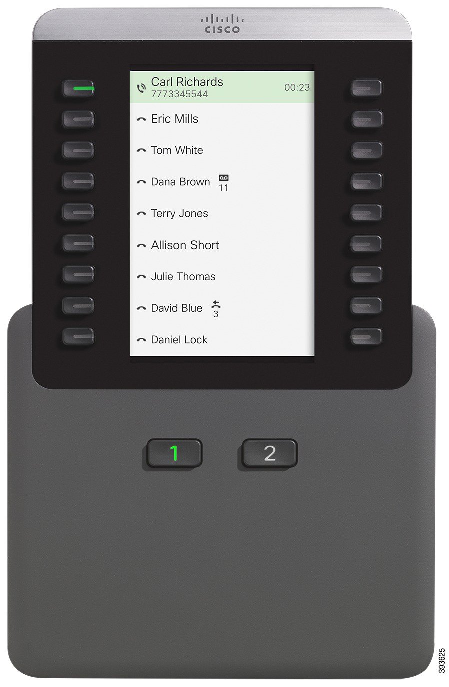
Also note the line mode when working with a key expansion module. In Session line mode, the first line key on the expansion module is line 6 of the phone template. In Enhanced line mode, it is line 11 of the phone template. Only the first 25 characters are displayed on a line.

Table 1. Available Line Keys in Each Session Mode

Cisco IP Phone Model

Single LCD screen expansion module

Dual LCD screen expansion module

Cisco IP Phone 8851 and 8851NR

Session Line Mode: 77

Session Line Mode: 61

Enhanced Line Mode: Not supported

Enhanced Line Mode: 66

Cisco IP Phone 8861

Cisco IP Phone 8865 and 8865NR

Session Line Mode: 113

Session Line Mode: 89

Enhanced Line Mode: Not supported

Enhanced Line Mode: 94

Figure 1. Cisco IP Phone 8865 with Three Cisco IP Phone 8865 Key Expansion Modules
Figure 2. Cisco IP Phone 8861 with Three Cisco IP Phone 8800 Key Expansion Modules

Key Expansion Module Buttons

The following figure and table describes the function and appearance of the buttons on the key expansion module.

Figure 3. Key Expansion Module Buttons
Table 2. Placement and Function of Key Expansion Module Buttons

LCD screen—Displays the phone number, speed-dial number (or name or other text label), phone service, phone feature, or privacy assigned to each button.

Icons that indicate line status resemble (in both appearance and function) the icons on the phone to which the key expansion module is attached.

1

Lighted buttons—Line buttons. Each button or pair of buttons corresponds to one line. The lights beneath each button indicate the state of the corresponding line as follows:

  • Light off—Line available or a call is ringing on an inactive page.

  • Green steady—Line in use by you, or you have a call on hold.

  • Green, flashing—Enhanced line mode only. You have a call on hold.

  • Red steady—Line in use by someone else or someone else has a call on hold on a shared line.

  • Red, flashing—Enhanced line mode only. Someone else has a call on hold on a shared line.

  • Amber steady—Line ringing.

  • Amber, flashing—Enhanced line mode only. Line ringing.

2

Page buttons—2 buttons. The button for page 1 is labeled as 1 and the button for page 2 is labeled as 2. The lights in each button indicate the state of the page as follows:

  • Green steady—Page is in view.

  • Light off—Page is not in view.

  • Amber steady—Page is not in view with one or more alerting calls on the page.

Column Mode for the Cisco IP Phone 8800 Key Expansion Module

If you are using the Cisco IP Phone 8800 Key Expansion Module, you can set it up in one-column mode or two-column mode. Set your mode from the Product Specific Configuration area of your Cisco Unified Communications Manager Administration. Two-column mode is the default on the Cisco IP Phone 8800 Key Expansion Module.

The Cisco IP Phone 8851/8861 Key Expansion Module and the Cisco IP Phone 8865 Key Expansion Module do not support two-column mode.


Note

If the label is longer than the display space in both one- and two-column mode, the text contains an ellipsis (…).


One-Column Mode

In one-column mode, each row in the display corresponds to one line accessed by either the left or right-side buttons. In this configuration, the key expansion module displays 9 lines on page 1, and 9 lines on page 2.

Figure 4. A Cisco IP Phone 8800 Key Expansion Module in One Column Mode

Two-Column Mode

In two-column mode, each of the buttons on the left and right of the screen is assigned to different lines. In this configuration, the key expansion module displays 18 lines on page 1, and 18 lines on page 2.

Figure 5. A Cisco IP Phone 8800 Key Expansion Module in Two Column Mode

Key Expansion Module Configuration on Cisco Unified Communications Manager

Key expansion modules are supported by most versions of Cisco Unified Communications Manager.

Set up the Key Expansion Module in Cisco Unified Communications Manager

Expansion modules are enabled from the Expansion Module Information area of the Phone Configuration page on Cisco Unified Communications Manager. If you configure the expansion module incorrectly, an error message displays on the phone. You cannot configure the phone for a dual LCD module and then install a single LCD module. But your choice of expansion module is not permanent. You can configure another module if your needs change.

Before you begin

As a best practice, enable power negotiation on both the switch and the phone. This ensures that the expansion module powers up.

Procedure


Step 1

In Cisco Unified Communications Manager Administration, choose Device > Phone.

The Find and List Phones window appears. You can search for one or more phones that you want to configure for the Cisco IP Phone 8800 Key Expansion Module.

Step 2

Select and enter your search criteria and click Find.

The Find and List Phones window appears with a list of phones that match your search criteria.

Step 3

Click the phone that you want to configure for the Cisco IP Phone 8800 Key Expansion Module. The Phone Configuration window appears.

Step 4

If you have an expansion module with a single LCD screen, scroll down to the Product Specific Configuration area. Enable the One Column Display for KEM field for one-column mode, or disable the field for two-column mode.

Step 5

Scroll down to the Expansion Module Information section. Select the appropriate expansion module for the Module 1 field.

Depending upon your phone, your choices may include:

  • CP-8800-Video 28 Button Key Expansion Module
  • CP-8800-Audio 28 Button Key Expansion Module
  • BEKEM 36-Button Line Expansion Module
Step 6

(Optional) Depending upon your phone model, you can add extra expansion modules. Repeat the previous step for Module 2, and Module 3.

Step 7

Click Save.

Step 8

Select Apply Config.

Step 9

Restart the phone.


Custom Background Images

You can customize a Cisco IP phone with a background image or wallpaper. Customized wallpapers are a popular way to display corporate logos or images and many organizations use them to make their phones stand out.

The phone analyzes the color of your wallpaper and changes the color of your font and icons so they can be read. If your wallpaper is dark, the phone changes the fonts and icons to white. If your wallpaper is light, the phone displays the fonts and icons as black.

But it is best to choose a simple image such as a solid color or pattern for your background. Also you should avoid high contrast images.

You add customized wallpaper in one of two ways:

  • Using the List file

  • Using a Common Phone Profile

If you want the user to be able to select your image from various wallpapers available on the phone, then modify the List file. But if you want to push the image to the phone, then create or modify an existing Common Phone Profile.

Regardless of your approach, note the following:
  • Your images must be in PNG format and the dimensions of the full sized image must be within 800 pixels by 480 pixels. Thumbnail images are 139 pixels (width) by 109 pixels (height).

  • Upload the images and List file to your TFTP server. The directory is Desktops/800x400. Restart the server after the upload is done.

  • If you modify your Common Phone Profile, then add the new image to the Background Image field in the format mylogo.png. If you don't want the user selecting their own wallpaper, then uncheck Enable End User Access to Phone Background Image Setting. Save and apply the phone profile. Restart the phones so your changes take effect.

For more information on customizing wallpaper, refer to the following documentation:

Connect a Key Expansion Module to a Cisco IP Phone

If you want to install more than one key expansion module, you repeat steps 7-9 to connect the other key expansion modules together.

Procedure


Step 1

Unplug the Ethernet cable from the phone.

Step 2

If installed, remove the footstand from the phone.

Step 3

Locate the accessory connector covers on the side of the phone.

This diagram shows the location.

Step 4

Remove the two accessory connector covers, as shown in the diagram.

Caution 

The slots are designed for the spine connector only. Insertion of other objects will cause permanent damage to the phone.

Step 5

Position the phone so that the front of the phone faces up.

Step 6

Connect one end of the key expansion module spine connector to the accessory connector on the Cisco IP Phone.

  1. Align the spine connector with the accessory connector ports.

    Note 

    Install the connector in the orientation shown in the following diagrams.

  2. Firmly press the spine connector into the phone.

This diagram shows the spine connector.

This diagram shows the installation of the spine connector.

Step 7

Connect the other end of the spine connector to the key expansion module as shown in this diagram.

  1. Align the spine connector with the key expansion module accessory connector ports.

  2. Firmly press the key expansion module into the spine connector.

Step 8

(Optional) Use a second key expansion module spine connector to connect the second key expansion module to the first key expansion module.

Step 9

(Optional) Use a third key expansion module spine connector to connect the third key expansion module to the second key expansion module.

Step 10

Use a screwdriver to fasten the screws into the phone.

This step ensures that the phone and key expansion module remain connected at all times. This diagram shows the location of the screw holes on the phone and one key expansion module.

Note 

Make sure that the screws are fully inserted into the phone and tightened.

If you lose any screws, the phone uses a standard M3 0.5x5.0mm screw.

Step 11

(Optional) Install the footstands on the phone and on the key expansion module, and adjust both footstands to rest evenly on the work surface.

Step 12

Plug the Ethernet cable into the phone.


Configure a Key Expansion Module on the Phone

After your administrator has configured your key expansion module, you can set it up and customize it from your phone.

Change the Wallpaper

Your administrator may allow you to change the wallpaper or background image.

Procedure


Step 1

Press Applications .

Step 2

Navigate Settings > Wallpaper.

Step 3

Select a wallpaper option and perform any of the steps:

  • Press Preview to see the wallpaper on your phone screen.
  • Press Set to apply the wallpaper to the phone.
Step 4

Press Exit.


Adjust the Key Expansion Module Screen Brightness

Procedure


Step 1

Press Applications .

Step 2

Select Settings > Brightness > Brightness - Key expansion module x, where x is the number of the key expansion module.

Step 3

Press right on the Navigation pad to increase brightness. Press left on the Navigation pad to decrease brightness.

Step 4

Press Save.


Place a Call on the Key Expansion Module

Procedure


Step 1

Press the line button on the key expansion module.

Step 2

Dial a phone number.

Step 3

Pick up your handset.


Troubleshoot the Key Expansion Module

Procedure


Step 1

Open a CLI.

Step 2

Enter the following command to enter debug mode:

debugsh

Step 3

Enter ? to see all available commands and options.

Step 4

Use the applicable commands and options to find the desired information.

Step 5

To exit debug mode, press Ctrl-C.


Access Key Expansion Module Setup

After you install one or more key expansion modules on the phone and configure them in Cisco Unified Communications Manager Administration, the phone automatically recognizes the key expansion modules.

When multiple key expansion modules are attached, they are numbered according to the order in which they connect to the phone:

  • Key expansion module 1 is the expansion module closest to the phone.

  • Key expansion module 2 is the expansion module in the middle.

  • Key expansion module 3 is the expansion module farthest to the right.

You can select a key expansion module, and then choose one of the following softkeys:

  • Exit: Returns to the Applications menu.

  • Details: Provides details about the selected key expansion module.

  • Setup: Allows you to configure the brightness of the selected key expansion module. Setting the brightness can also be done using the Preferences menu on the phone.

Procedure


Step 1

On the phone, press Applications .

Step 2

Press Accessories.

All properly installed and configured key expansion modules display in the list of accessories.


Reset the Single LCD Screen Key Expansion Module

If you are having technical difficulties with your Cisco IP Phone 8800 Key Expansion Module, you can reset the module to the factory default settings.

Procedure


Step 1

Restart the key expansion module by disconnecting the power source, waiting a few seconds, and then reconnecting it.

Step 2

As the key expansion module powers up, press and hold Page 1. As the LCD screen turns white, continue pressing Page 1 for at least one second.

Step 3

Release Page 1. The LEDs turn red.

Step 4

Immediately press Page 2 and continue pressing Page 2 for at least one second.

Step 5

Release Page 2. The LEDs turn amber.

Step 6

Press Lines 5, 14, 1, 18, 10, and 9 in sequence.

The LCD screen turns blue. A spinning icon is displayed in the center of the screen.

The key expansion module resets.


Reset the Dual LCD Screen Key Expansion Module

If you are having technical difficulties with your dual LCD screen key expansion module, you can reset the module to the factory default settings. This task applies only to the Cisco IP Phone 8865 Key Expansion Module and the Cisco IP Phone 8851/8861 Key Expansion Module.

Procedure


Step 1

Restart the module by disconnecting it and then reconnecting it to the phone.

Step 2

As the module powers up, hold down both of the page keys until the LEDs on the first 7 line keys turn green.


Key Expansion Module Power Information

If you use a key expansion module with your phone, then Power over Ethernet (PoE) is often enough to power your expansion modules. But a power cube is required for a Cisco IP Phone 8851/8861 Key Expansion Module or a Cisco IP Phone 8865 Key Expansion Module supported by 802.3af PoE. A power cube is also needed for smartphone or tablet charging when your expansion module is attached.

Cisco IP Phone 8800 Key Expansion Module Power Consumption

48V DC, 5W per key expansion module

Cisco IP Phone 8851/8861 Key Expansion Module and Cisco IP Phone 8865 Key Expansion Module Power Consumption

48V DC, 3.5W per key expansion module

Cisco IP Phone 8800 Key Expansion Module, Cisco IP Phone 8851/8861 Key Expansion Module, and Cisco IP Phone 8865 Key Expansion Module Power Scheme

The phone can power one key expansion module directly. For more information, see the Power-Supply Compatibility Table.

If you are charging a smartphone or a tablet, the side USB draws up to 500mA/2.5W.

Table 3. Power-Supply Compatibility Table

Configuration

802.3af Power over Ethernet (PoE)

802.3at PoE

Cisco IP Phone Power Cube 4

8851 and 1 expansion module

Yes

Yes

Yes

8851 and 2 expansion modules

No

No

See the third note.

Yes

8861 and 1 expansion module

No

Yes

Yes

8861 and 2 expansion modules

No

Yes

See the first note.

Yes

8861 and 3 expansion modules

No

Yes

See the first note.

Yes

8865 and 1 expansion module

No

Yes

Yes

8865 and 2 expansion modules

No

Yes

See the second note.

Yes

8865 and 3 expansion modules

No

Yes

See the second note.

Yes


Note

Be familiar with the following items:

  • Cisco IP Phone 8861 using 802.3at PoE: The fast-charging feature on the back USB is not supported when more than one expansion module is used.

  • Cisco IP Phone 8865: The fast-charging feature on the back USB requires Cisco Universal PoE (UPoE) when more than one expansion module is attached.

  • Cisco IP Phone 8851 with 2 expansion modules: 802.3at PoE is supported only with v08 or later hardware. You can find the phone version information on the lower back of the phone as part of the TAN and PID label. Version information is also located on the individual phone packaging.