Your new ATA
Your analog telephone adapter (ATA) allows you to connect an analog device, such as an analog phone or fax machine, to your network. The connected device can then function like the IP phones in your network.
Your new analog telephone adapter (ATA) has two interfaces:
-
Two RJ11 ports for analog devices
-
A RJ45 port for Ethernet
Light-emitting diodes (LEDs) on the ATA provide status.
Install your ATA with the components that are included in the box.
-
Install your ATA with the components in the box.
Cisco ATA 191 Hardware
The ATA 191 and ATA 192 are compact, easy to install devices.
The unit provides these connectors:
-
5V DC power connector.
-
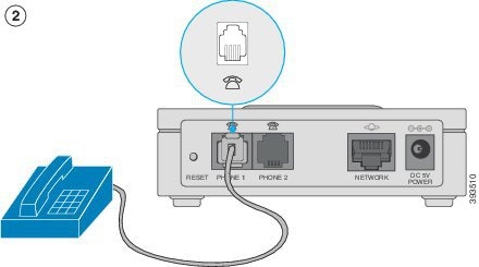
Two RJ-11 FXS (Foreign Exchange Station) ports—Your ATA has two RJ-11 ports that work with any standard analog phone device. Each port supports either voice calls or fax sessions, and both ports can be used simultaneously.
-
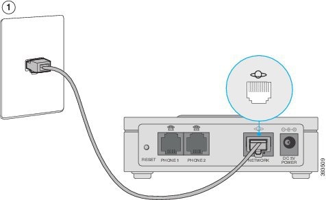
One WAN network port—An RJ-45 10/100BASE-T data port to connect an Ethernet-capable device to the network.
 Note |
The ATA network port performs autonegotiation for duplex and speed. It supports speeds of 10/100Mbps and full-duplex. |
ATA 191 Top Panel
The top panel of your ATA has several LEDs that are used to show the device's status.
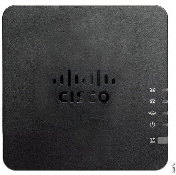
The following table describes the LEDs located on your ATA.
|
Item |
Description |
||
|---|---|---|---|
|
Power LED
|
Steady green: System booted up successfully and is ready for use. Slow flashing green: System is booting up. Fast flashing green three times, then repeats: System failed to boot up. Fast flashing green: The LED behaviour occurs in the following situations:
Off: Power is off. |
||
|
Network LED
|
Flashing green: Data transmission or reception is in progress through the WAN port. Off: No link. |
||
|
Phone 1 LED Phone 2 LED
|
Steady green: On hook. Slow flashing green: Off hook. Fast flashing green three times, then repeats: The analog device failed to register. Fast flashing green: A factory reset is performed successfully. Off: The port is not configured. |
||
|
Problem Report Tool (PRT) Button |
Press this button to create a problem report using the Problem Report Tool.
|
||
|
Problem Report Tool (PRT) LED
|
Flashing amber: The PRT is preparing the data for the problem report. Fast Flashing amber: The PRT is sending the problem report log to the PRT server. Solid green for five seconds, then off: The PRT report was sent successfully. Fast flashing green: A factory reset is performed successfully. Flashing red: The PRT report failed. Press the PRT button to turn the LED off. Once it is off, another press triggers a new PRT report. |


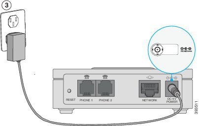
ATA 191 Back Panel
The back panel of your ATA has several ports used to connect your device and to power it. The back panel also has the reset button for resetting the device to the factory settings.
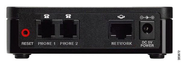
The following table describes the ports that are located on the back panel of your ATA.
|
Port or Button |
Description |
|---|---|
|
RESET |
To restart the ATA, use a paper clip or similar object to press this button briefly. To restore the factory default settings, press and hold for 10 seconds. The LED behaviour for the factory reset:
|
|
PHONE 1 |
Use an RJ-11 phone cable to connect an analog phone or fax machine. |
|
PHONE 2 |
Use an RJ-11 phone cable to connect a second analog phone or fax machine. |
|
NETWORK |
Use an Ethernet cable to connect to the network. |
|
DC 5V POWER |
Use the provided power adapter to connect to a power source. |


 Feedback