Installation

This chapter describes the installation of the node.

Tools and Test Equipment

The following tools and equipment are required for installation.

  • Torque wrench capable of 5 to 12 ft-lbs (6.8 to 16.3 Nm)

  • 4-inch to 6-inch extension for torque wrench

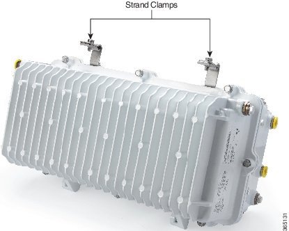
  • 1/2-inch socket for strand clamp bolts and cover bolts

  • 1/4-inch flat-blade screwdriver

  • #2 Phillips-head screwdriver

  • Long-nose pliers

  • 1/2-inch deep-well socket for seizure connector

  • True-RMS digital voltmeter (DVM)

  • EXFO FOT 22AX optical power meter with adapters

  • Optical connector cleaning supplies

  • Optical connector microscope with appropriate adapters for your optical connectors

Node Fastener Torque Specifications

Be sure to follow these torque specifications when assembling/mounting the node.

Fastener

Torque Specification

Illustration

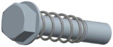
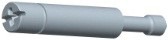
Housing closure bolts

5 to 12 ft-lbs

(6.8 to 16.3 Nm)

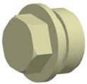
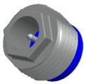
Test point port plugs

Housing plugs

5 to 8 ft-lbs

(6.8 to 10.8 Nm)

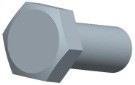
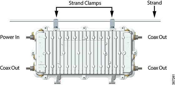
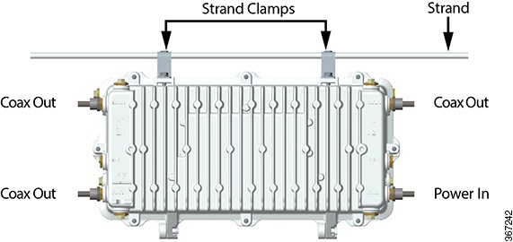
Strand clamp mounting bracket bolts

5 to 8 ft-lbs

(6.8 to 10.8 Nm)

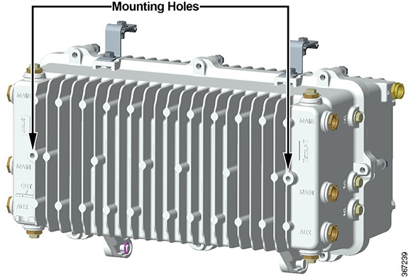
Pedestal mounting bolts

8 to 10 ft-lbs

(10.8 to 13.6 Nm)

Module securing screws

25 to 30 in-lbs

(2.8 to 3.4 Nm)

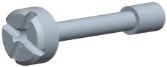
RF Amplifier assembly shoulder screws (cross head screw)

18 to 20 in-lbs

(2.0 to 2.3 Nm)

Seizure nut

2 to 5 ft-lbs

(2.7 to 6.8 Nm)
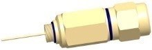
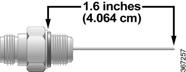
RF cable connector

Per manufacturer instructions

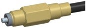
Fiber optic cable connector

20 to 25 ft-lbs

(27.1 to 33.9 Nm)

Node Housing Ports

The following illustration shows the location of available RF ports, fiber ports, and test points on the node housing.


Note

When replacing test point port plugs, torque from 5 to 8 ft-lbs (6.8 to 10.8 Nm).


Strand Mounting the Node

The following procedure explains how to install the node on a strand (aerial installation). Strand mounting allows street-side access to the housing, and the housing does not need to be opened.


Warning

  • Be aware of the size and weight of the node while strand mounting. Ensure that the strand can safely support the node’s maximum weight. A fully loaded node weighs over 50 lbs (22.7 kg).

  • Ensure the ground area below the installation site is clear of personnel before hoisting the node. If possible, block off walkway below the hoisting area to prevent pedestrian traffic during hoisting.

  • Failure to observe these admonishments can result in serious injury or death.


  1. Check the strand size. The minimum strand diameter should be 5/16 inch.

  2. Attach the strand clamp brackets to the housing in the position shown in the following illustration. Use a torque wrench tightens the strand clamp bracket bolts from 5 ft-lb to 8 ft-lbs (6.8 to 10.8 Nm).

  3. Loosen the strand clamp bolts to separate the clamps enough to insert the strand, but do not remove them. Then lift the housing into proper position on the strand.

  4. Slip the clamps over the strand and finger-tighten the clamp bolts. This allows additional side-to-side movement of the housing as needed.

  5. Move the housing as needed to install the coaxial cable and connectors. See the illustrations below for an example.

    Figure 1. Powered from Left
    Figure 2. Powered from Right

    Note

    If supplying power to the node through a main output port, a power inserter must be installed to inject the AC voltage onto the RF signal.


  6. Use a torque wrench and a 1/2-inch socket to tighten the strand clamp bolts from 5 ft-lb to 8 ft-lbs (6.8 to 10.8 Nm).


    Note

    A slight tilt of the face of the housing is normal. Cable tension will cause the housing to hang more closely to vertical.


  7. Connect the coaxial cable to the pin connector according to the pin connector manufacturer’s specifications.

  8. Continue to Fiber Optic Cable Installation and RF Cable Installation.

Pedestal or Wall Mounting the Node

Two mounting holes on the housing allow pedestal or wall mounting.

Follow this procedure for pedestal or wall mounting.


Warning

  • Be aware of the size and weight of the node while mounting. A fully loaded node weighs nearly 50 lbs (22.7 kg).

  • Ensure that proper handling/lifting techniques are employed when working in confined spaces with heavy equipment.

  • Failure to observe these warnings can result in serious injury or death.


  1. Remove the cover of the pedestal.

  2. Remove the self-tapping bolts from the strand clamps, if previously installed, and set the bolts and strand clamps aside.

  3. Position the node horizontally in the enclosure and allow for free flow of air around it. Inadequate airflow could cause the node to exceed thermal parameters. Line up the bolt holes on the bottom of the housing with the mounting holes on the pedestal bracket provided by the pedestal manufacturer.


    Important

    The node housing must be mounted horizontally, as shown, to ensure proper airflow over the housing cooling fins. Do NOT mount the node housing vertically.


  4. Secure the node housing to the pedestal bracket using the strand clamp bracket bolts you removed in step 2. Insert the bolts into the mounting holes. Use the strand clamps as spacers if necessary. Torque the bolts from 8 ft-lb to 10 ft-lb (10.8 Nm to 13.6 Nm).

  5. Connect the coaxial cable to the pin connector according to connector manufacturer’s specifications.

  6. Ground the equipment in accordance with local codes and regulations.

  7. Continue to Fiber Optic Cable Installation and RF Cable Installation.

Fiber Optic Cable Installation

The node can accept a fiber optic cable connector from either the right or left side of the housing, or both. The fiber optic cable(s) carries forward and reverse optical signals.

This procedure assumes a specific type of connector as an example. Your connector may be different from the one shown in these illustrations. Be sure to install the connector according to the connector manufacturer’s instructions.


Important

Fiber optic cable installation is a critical procedure. Incorrect installation can result in severely degraded node performance. Be sure to carefully follow fiber connector manufacturer’s instructions. See Care and Cleaning of Optical Connectors.


Color Code

Fiber connectors and adapters are labeled with the following color code.


Note

This is only a suggested setup. Your fiber assignment may be different. Refer to your network diagrams to verify your color code.


Connector/Adapter Number

Fiber Color Code

Connects to

1

Blue

forward receiver 1

2

Orange

forward receiver 2

3

Green

reverse transmitter 1

4

Brown

reverse transmitter 2

5

Slate

spare

6

White

spare

7

Red

spare

8

Black

spare

Fiber Management System

The fiber management system is made up of a fiber tray and a fiber routing track. The fiber tray provides a convenient location to store excess fiber and up to two WDM modules in the node. The tray is hinged to allow it to move out of the way during the insertion of the fibers and for installation or replacement of the node power supplies. The fiber routing track provides a channel for routing fiber pigtails to their appropriate optical modules as well as a location to snap in unused fiber connectors for storage.

The following illustration shows the design of the fiber tray.


Note

Fibers are spooled in a counterclockwise direction in the tray.


The following illustrations show the location and layout of the fiber tray and track in the housing lid.

Install Fiber Optic Cable

Install fiber optic cable as described below.


Warning

Laser light hazard. The laser light source on this product emits invisible laser radiation. Avoid direct exposure. Never look into the end of an optical fiber or connector. Failure to observe this warning can result in eye damage or blindness.


  • Do not apply power to this product if the fiber is unmated or unterminated.

  • Do not stare into an unmated fiber or at any mirror-like surface that could reflect light that is emitted from an unterminated fiber.

  • Do not view an activated fiber with optical instruments.

  1. The first step depends on whether the fiber optic cable is factory installed or not.

    IF...

    THEN...

    fiber optic cable is factory installed

    splice fiber pigtail of optical fiber input cable to your splice enclosure and continue to RF Cable Installation.

    fiber optic cable is not installed

    go to step 2.

  2. Select the right or left fiber connection port for use and remove its sealing plug.

  3. Push in the two release tabs at the top of the fiber tray and swivel the top of the fiber tray up and back to allow a clear view of the fiber routing channel below.

  4. One at a time, carefully insert fibers with attached connectors through the fiber connection port, the fiber channel, and then up and through the fiber entry point in the bottom of the fiber tray. Do not bend or kink fibers. Though not necessary, you can also remove the power supplies and open the fiber routing channel cover for additional access.


    Note

    If using the alternate (right-side) fiber connection port, you have to route the fibers through the fiber channel in the fiber track located underneath the unused fiber holders.


  5. Hold the connector body to prevent rotation of the connector or fibers.

  6. Carefully thread the 5/8-inch threaded nut into the threaded hole of the fiber port. Tighten to 20 to 25 ft-lbs (27.1 to 33.9 Nm).

  7. Firmly tighten the rotational nut against the 5/8-inch threaded nut.

  8. Push heat shrink tubing over the connector and fiber port and shrink in place.

  9. Identify individual fibers according to their color code and determine to which receiver or transmitter module each fiber will connect.

  10. Pivot the fiber tray back down and snap it into place on top of the power supply with its locking tabs.

  11. Open the fiber tray cover and carefully wind the fibers around the spool in a counterclockwise direction. Be sure to leave enough fiber so that each connector can reach its intended module. Note that different diameter spool paths are provided to properly adjust the fiber length.

  12. Route each fiber to its intended module through the fiber track as shown.

  13. Before connection, carefully clean the optical connectors on both fiber and module according to the procedures in Care and Cleaning of Optical Connectors.

  14. Open the receiver or transmitter module fiber connector cover. Carefully slide the fiber connector into the module connector until it clicks.

  15. Repeat steps 12 and 13 for each receiver and transmitter module.

  16. Splice fiber pigtail of optical fiber input cable to your splice enclosure.

  17. Continue to RF Cable Installation.

RF Cable Installation

The node can accept up to four RF cables. These cables carry forward path RF signal outputs and reverse path RF signal inputs. The RF cables also supply the 45 to 90 V AC power input. Power can also be supplied through the 2 Ports (3 and 6) which do not support RF signals.

Trimming the Center Conductor

The node requires pin-type connectors for all RF connections.

Standard pin connectors, with pins extending 1.5 in. to 1.6 in. (3.8 cm to 4.064 cm) from connector shoulder, require no trimming. You must trim longer pins before inserting them into the housing.

Trimming Using the Integrated Cradle

To trim long pins using the integrated cradle, follow these steps.

  1. Place the connector on the cradle as shown in the following illustration.

  2. If the center conductor extends past the CUT stanchion on the housing, trim the pin flush with the end of the CUT stanchion.

  3. Remove any burrs or sharp edges from the trimmed end of the pin.

Trimming Using the Strip Line Mark

To trim long pins using the strip line mark on the housing, follow these steps.

  1. Place the connector above the entry port so that it lines up with its installed position.

  2. If the center conductor extends past the STRIP line on the housing, trim the pin flush with the STRIP line.

  3. Remove any burrs or sharp edges from the trimmed end of the pin.

Connecting the RF Cables to the Node Housing

Follow these steps to connect the RF cables.

  1. Determine which ports receive an RF cable for your configuration.

  2. The length of the RF connector center pin is critical to proper operation. The pin length must be 1.6 inches (4.064 cm). Trim pin if necessary before installation. See Trimming the Center Conductor.


    Note

    Assemble each RF connector to its cable according to manufacturer’s instructions.


  3. Remove the sealing plug of each port to which cables connect. Note that Ports 1, 3, 4, and 6 have the option of a vertical or horizontal connection.

  4. Insert the appropriate coaxial connector of each RF cable to the desired housing port and torque to the manufacturer’s specification. Do not exceed recommended torque.

  5. Repeat steps 2 through 4 for each RF port used.

  6. Continue to Applying Power to the Node.

Applying Power to the Node

The node requires input power of 45 to 90 V AC from an external power source. This power is supplied through one or more of the RF cables.

The powering configuration is flexible and can be changed to meet most network requirements. Power direction is configured by installing AC shunts for the ports through which you want to pass AC power. An AC segmentable shunt is provided to configure power direction between the two sides of the node.

The following schematic diagram illustrates node powering.

Node Powering Procedure

Follow these steps to apply power.

  1. Determine which of the RF cables carry 45 to 90 V AC input power.

  2. Install shunts in the locations that correspond to the AC-powered RF ports. Each port’s shunt is located on the RF amplifier module near the port as shown in the following illustration.


    Note

    Shunts are available with both red and black tops. Use red to indicate that power is applied to that port. Use black to indicate that input power is not applied.


  3. If desired, remove shunts to block AC power at the individual ports.

  4. The next step depends on the power path, as follows:

    IF...

    THEN...

    power will pass from left side of housing (Ports 1, 2, and 3) to right side of housing (Ports 4, 5, and 6)

    ensure that the AC segmentable shunt is installed.

    power is to be blocked between left side of housing (Ports 1, 2, and 3) and right side of housing (Ports 4, 5 and 6)

    ensure that the AC segmentable shunt is removed.

    Ports 1, 2, and 3 are powered from one source and Ports 4, 5 and 6 are powered from another source

    ensure that the AC segmentable shunt is removed.

  5. Continue to Voltage Check Procedure.

Voltage Check Procedure

Always check both AC and DC voltages during initial setup of the node.

Follow these steps to check AC and DC voltages.

  1. Use a true-rms DVM to check for 45 to 90 V AC input voltage at the AC test point on the power supply module.

  2. Check for the various DC output voltages (+24.5, +8.5, -6.0, and +5.5) of the power supply at the DC test points on the power supply module.

  3. Verify that the LED on the OIB is on.

  4. Carefully close the housing lid. See Opening and Closing the Housing.