General Information

This manual describes the installation and operation of the Cisco GS7000 Super High Output Intelligent Node (iNode). The iNode is designed to operate using the Cisco 1X2 Remote PHY device rather than standard optical transmitter and receivers from the traditional GS7000 node. The iNode contains microprocessor based setup, balance, and troubleshooting capability.

Physical Description

This node is the latest generation 1.2 GHz optical node in the GS7000 Node platform. It is based on the same housing developed for the original GS7000 Node Platform. The node is designed to eliminate the need for installing and maintaining the typical amplifier plug-in accessories such as pads, equalizers, trims and signal directors. It also eliminated the need for external test points with circuitry that can remotely report and display RF levels and RF spectrum via Cisco Intelligent Node software. It can eliminate manual tuning and the need for skilled RF technicians to install and maintain the devices in the field. The housing has a hinged lid to allow access to the internal electrical and optical components. The housing also has provisions for strand, pedestal, or wall mounting.

The base of the housing contains:

  • an RF amplifier module

  • AC power routing

The lid of the housing contains:

  • a fiber management tray and track

  • power supplies (one or two)

  • Intelligent Remote PHY Device

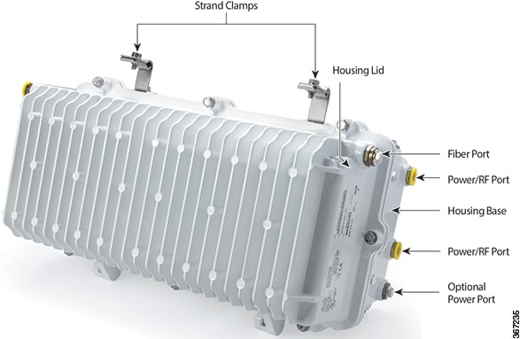
The following illustration shows the external housing of the node.

Figure 1.

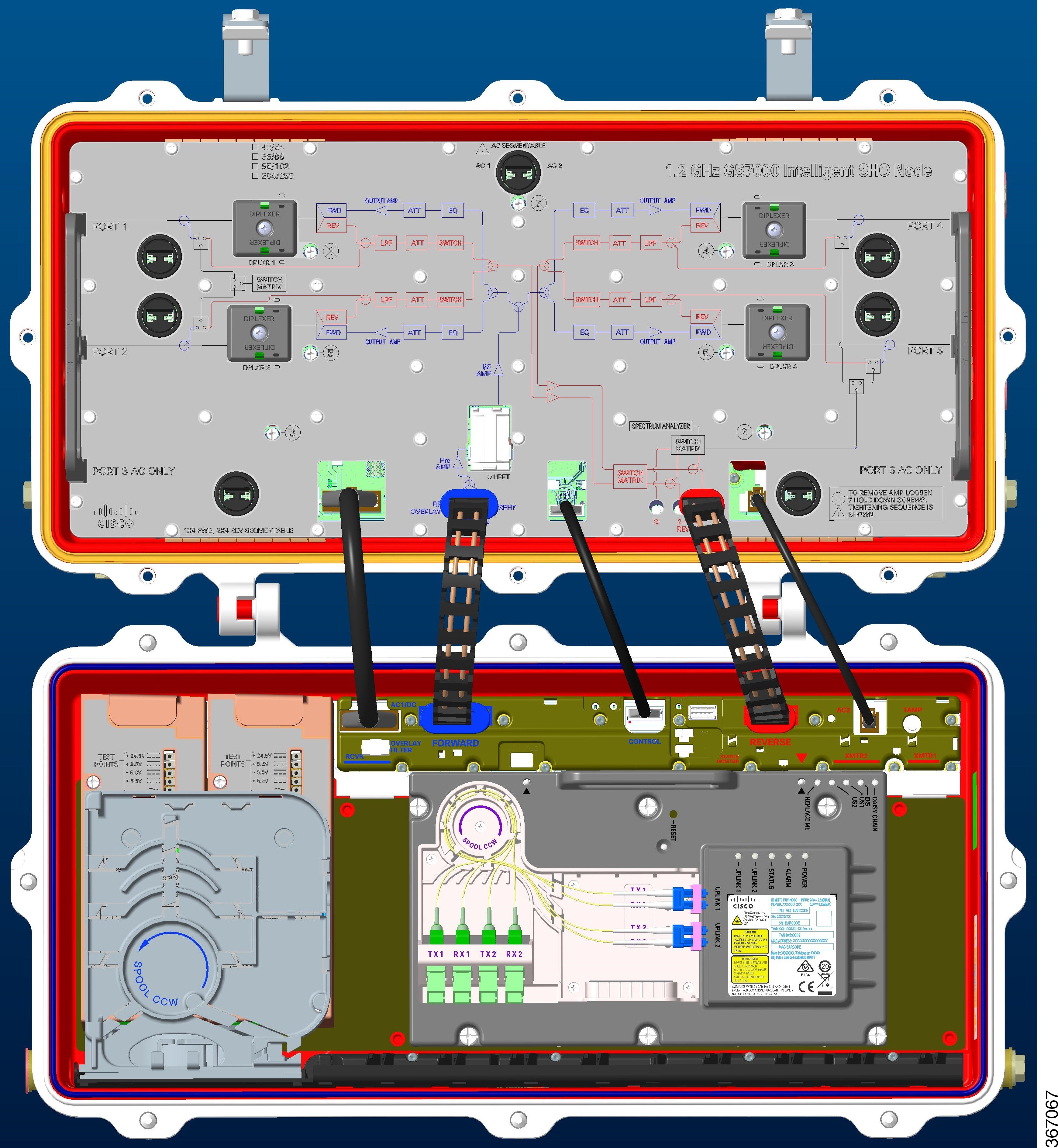
The following illustration shows the node internal modules and components.

Functional Description

The node is used in broadband hybrid fiber/coax (HFC) networks.

The node receives forward optical inputs, converts the input to an electrical radio frequency (RF) signal, and outputs the RF signals to up to four ports. The forward bandpass frequency is from 54 MHz to 1218 MHz. The lower edge of the passband is primarily determined by the frequency split of the diplex filters and the reverse amplifier assembly.

The Cisco GS7000 Intelligent Node will contain a Cisco Remote PHY Device (RPD) in lieu of the optical receivers and transmitters which have been used in previous versions of the GS7000 nodes.

The RPD will allow for a single forward/downstream path to be split to up to 4 RF ports. The reverse/upstream path can combine all 4 RF ports onto a single upstream signal or can be split into 2 upstream paths via a switch in the node. No change of a configuration module is required to switch from a combined to segmented reverse path as with earlier GS7000 nodes.

The Remote PHY module communicates with the headend/hub via the Small Form Factor Pluggable (SFP) device which plugs into the module. This transceiver is the optical port for all forward and reverse traffic to/from the Intelligent Node.

45 - 90 V AC input power is converted to +24.5, +8.5, -6.0, and +5.5 V DC by an internal power supply to power the node.

Node Inputs/Outputs Diagram

The following diagram shows the system-level inputs and outputs of the node.


Note

Port 3 and Port 6 are only for power.

  • The AC can be applied through any housing base port and routed, if required, to the other ports.

  • The DC power supply modules can be fed by any housing base port (1 through 6).


Module Functional Description

This table briefly describes each module. See Theory of Operation for detailed descriptions of the modules.

Module

Description

RF Amplifier

The RF Amplifier Module includes:

  • four forward RF output ports

  • four reverse inputs

  • forward and reverse bandwidths that are established by diplexer and reverse low pass filter assembly selection

Remote PHY Device (iRPD)

The Remote PHY Device includes:

  • two SFP+ 10G interfaces

  • one CONSOLE interface

  • 50-pin B2B connector interface between iRPD and OIB

  • 1 DS X 2 US Physical RF ports between iRPD and GS7000

Power Supply

The node power supply module has multiple output voltages of +24.5, +8.5, -6.0, and +5.5 V DC. A second power supply can be installed in the node for redundancy or load sharing.

The node can be set up in the following powering configurations:

  • two power supplies powered by different AC sources

  • two power supplies using the same AC source

  • a single supply using a single AC source

Fiber Management Tray and Track

The fiber management system secures and protects the optical fiber inside the node housing.

Optical Interface Board

The Optical Interface Board (OIB) provides all interconnections between the modules in the housing lid to the RF amplifier module in the housing base. Each module in the lid plugs directly into the OIB through a connector header or row of sockets depending on the module type. A forward path electronic controlled attenuator is provided on the OIB for the setup of the Remote PHY device in the housing lid. A separate reverse path electronic controlled attenuator is also provided on the OIB for the setup of the Remote PHY device.

Amplifier Output Linear Tilt Chart

The following chart can be used to determine the operating level at a particular frequency considering the operating linear tilt.

If the amplifier’s 1 GHz output level is 49.0 dBmV with a linear operating tilt of 14.5 dB (from 50 to 1 GHz), the corresponding output level at 750 MHz would be 45.1 dBmV. This was found by taking the difference in tilt between 1 GHz and 750 MHz (14.5 – 10.6 = 3.9 dB). Then subtract the difference in tilt from the operating level (49.0 - 3.9 = 45.1 dBmV).

Ordering Information

Please refer to the iNode Data Sheet for a full listing of the configured node, components, and accessories that are available.


Note

Please consult with your Account Representative, Customer Service Representative, or System Engineer to determine the best configuration PID for your particular application.